
Subscribe to Our Youtube Channel
Related Manuals for Sun Microsystems SPARC Series


Summary of Contents for Sun Microsystems SPARC Series
- Page 1 Sun SPARC Enterprise ® M3000 Server Service Manual Sun Microsystems, Inc. www.sun.com Part No. 820-5683-11 January 2009, Revision A Submit comments about this document at: http://www.sun.com/hwdocs/feedback...
- Page 2 Fujitsu Limited or Sun Microsystems, Inc., or any affiliate of either of them.
- Page 3 Aucune partie de ce produit, de ces technologies ou de ce document ne peut être reproduite sous quelque forme que ce soit, par quelque moyen que ce soit, sans l’autorisation écrite préalable de Fujitsu Limited et de Sun Microsystems, Inc., et de leurs éventuels bailleurs de licence.
-
Page 5: Table Of Contents
Contents Preface xiii Safety Precautions for Maintenance 1–1 ESD Precautions 1–1 Server Precautions 1–3 1.2.1 Electrical Safety Precautions 1–3 1.2.2 Equipment Rack Safety Precautions 1–3 1.2.3 Component Handling Precautions 1–4 Hardware Overview 2–1 Name of Each Part 2–1 Operator Panel 2–4 2.2.1 Operator Panel Overview 2–5 2.2.2... - Page 6 Failure Diagnostic Method 3–2 Checking the Server and System Configuration 3–4 3.3.1 Checking the Hardware Configuration and FRU Status 3–4 3.3.1.1 Checking the Hardware Configuration. 3–5 3.3.2 Checking the Software and Firmware Configurations 3–5 3.3.2.1 Checking the Software Configuration 3–6 3.3.2.2 Checking the Firmware Configuration 3–7 3.3.2.3...
- Page 7 3.6.2.1 Options 3–19 3.6.3 Using the prtconf Command 3–21 3.6.3.1 Options 3–22 3.6.4 Using the netstat Command 3–24 3.6.4.1 Options 3–24 3.6.5 Using the ping Command 3–25 3.6.5.1 Options 3–25 3.6.6 Using the ps Command 3–26 3.6.6.1 Options 3–27 3.6.7 Using the prstat Command 3–27 3.6.7.1 Options 3–28...
- Page 8 4.5.2 FRU Removal and Replacement 4–12 4.5.3 Powering on the Server 4–13 4.5.3.1 Power-on by Using the XSCF Command 4–13 4.5.3.2 Power-on by Using the Operator Panel 4–13 4.5.4 Verifying the Hardware Operation 4–15 Internal Components Access 5–1 Sliding the Server Into and Out of the Equipment Rack 5–1 5.1.1 Sliding the Server Out from the Equipment Rack 5–1 5.1.2...
- Page 9 Installing the DIMMs 7–5 Reassembling the Server 7–5 Replacement and Installation of PCIe Cards 8–1 Accessing a PCIe Card 8–3 Removing a PCIe Card 8–4 Mounting a PCIe Card 8–4 Reassembling the Server 8–5 Replacement and Installation of a Hard Disk Drive (HDD) 9–1 Accessing a Hard Disk Drive 9–3 Removing a Hard Disk Drive 9–3 Installing a Hard Disk Drive 9–5...
- Page 10 12.4 Reassembling the Server 12–5 Fan Unit Replacement 13–1 13.1 Accessing a Fan Unit 13–3 13.2 Removing a Fan Unit 13–3 13.3 Mounting a Fan Unit 13–5 13.4 Reassembling the Server 13–5 Fan Backplane Replacement 14–1 14.1 Accessing the Fan Backplane 14–2 14.2 Removing the Fan Backplane 14–5 14.3...
- Page 11 C.2.3 CPU C–4 C.2.4 XSCF Unit C–4 Drive C–5 C.3.1 Hard Disk Drive C–5 C.3.2 CD-RW/DVD-RW Drive Unit (DVDU) C–6 Power Supply Unit C–6 Fan Unit C–7 D. External Interface Specifications D–1 Serial Port D–2 UPC Port D–2 USB Port D–3 SAS port D–3 Connection Diagram for Serial Cable D–4 E.
- Page 12 SPARC Enterprise M3000 Server Service Manual • January 2009...
-
Page 13: Preface
Preface ® The Sun SPARC Enterprise M3000 Server Service Manual describes how to service the Sun SPARC Enterprise M3000 server. References herein to the SPARC Enterprise M3000 server and the M3000 server are references to the Sun SPARC Enterprise M3000 server. This document is written for maintenance providers who have received formal service training or customers who have received training under a self-maintenance contract. - Page 14 How This Document Is Organized This document is organized into the following chapters: Chapter 1 safety precautions required for maintenance explains Chapter 2 explains the names of components and the LEDs on the operator panel and rear panel. Chapter 3 explains fault diagnosis information.
- Page 15 Related Documentation The documents listed as online are available at: http://docs.sun.com/app/docs/prod/sparc.m3k~m3000-hw#hic For late-breaking information about hardware, software, or documentation for the Sun SPARC Enterprise M3000 server, refer to the Sun SPARC Enterprise M3000 Server Product Notes. Application Title Format Location Overview Sun SPARC Enterprise M3000 Server Overview Online...
- Page 16 Documentation, Support, and Training Sun Function Documentation http://www.sun.com/documentation/ Support http://www.sun.com/support/ Training http://www.sun.com/training/ Sun Welcomes Your Comments Sun is interested in improving its documentation and welcomes your comments and suggestions. You can submit your comments by going to: http://www.sun.com/hwdocs/feedback Please include the title and part number of your document with your feedback: Sun SPARC Enterprise M3000 Server Service Manual, part number 820-5683-11 SPARC Enterprise M3000 Server Service Manual •...
-
Page 17: Safety Precautions For Maintenance
C H A P T E R Safety Precautions for Maintenance This chapter provides safety precautions required for maintenance. Section 1.1, “ESD Precautions” on page 1-1 ■ Section 1.2, “Server Precautions” on page 1-3 ■ ESD Precautions To ensure that you and bystanders are not exposed to harm and to prevent damage to the system, observe the following safety precautions. - Page 18 Wrist Strap Connection Destination FIGURE 1-1 FRU other than the units on the left: ■ 1 place either at the upper right on the front of the server or at the upper left at the back. Hard disk drive or fan unit: ■...
-
Page 19: Server Precautions
Server Precautions When maintaining the server, observe the following precautions for your protection. Follow all cautions, warnings, and instructions marked on the server. ■ Caution – Do not insert any object in an opening of the server. If any object comes into contact with a high-voltage part or short-circuits a component, fire or electric shock might result. -
Page 20: Component Handling Precautions
When the equipment rack is mounted on a raised floor, ensure that the raised ■ floor has sufficient strength to withstand the weight upon it when the server is extended on its slide rails. Fix the equipment rack through the raised floor to the concrete floor below it, using a proprietary mounting kit for this purpose. - Page 21 Caution – When removing a cable such as the LAN cable, if your fingers do not reach the latch lock of the connecter, use a flat head screwdriver to push the latch to disconnect the cable. If you forcibly insert your fingers into the service clearance, the LAN port of the motherboard unit of PCI Express (PCIe) cards may be damaged.
- Page 22 SPARC Enterprise M3000 Server Service Manual • January 2009...
-
Page 23: Hardware Overview
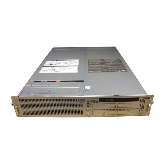
C H A P T E R Hardware Overview This chapter explains the names of components and also explains the LEDs on the operator panel and rear panel. Section 2.1, “Name of Each Part” on page 2-1 ■ Section 2.2, “Operator Panel” on page 2-4 ■... - Page 24 , and are the internal view, front view, and rear view FIGURE 2-1 FIGURE 2-2 FIGURE 2-3 of the server, respectively, and they indicate the names and abbreviated names of main components. Server (Internal View) FIGURE 2-1 Fan backplane (FANBP_B) Memory (DIMM) XSCF unit (XSCFU) PCIe...
- Page 25 Server (Front View) FIGURE 2-2 CD-RW/DVD-RW drive unit (DVDU) Operator panel (OPNL) Fan unit (FAN_A) Hard disk drive (HDD) Server (Rear View) FIGURE 2-3 Serial port RCI port Power supply unit (PSU) PCIe slot USB port LAN port controller SAS port Gigabit Ethernet (GbE) port (UPC) port Chapter 2...
-
Page 26: Operator Panel
Operator Panel The operator panel has the important function of controlling the power of the server. The operator panel is usually locked with a key to prevent the server from being mistakenly powered off during system operation. Before starting maintenance work, ask the system administrator to unlock the operator panel. -
Page 27: Operator Panel Overview
2.2.1 Operator Panel Overview The system administrator or service engineer checks the operating status of the server with LEDs or operates the power supply with the power switch. FIGURE 2-4 shows the location of the operator panel. Operator Panel Location FIGURE 2-4 Location number Component... -
Page 28: Switches On The Operator Panel
2.2.2 Switches on the Operator Panel depicts the functions of the switches on the operator panel. TABLE 2-1 The switches on the operator panel include the mode switch for setting the operation mode and the power switch for turning on and off the server. Switches (Operator Panel) TABLE 2-1 Switch... - Page 29 shows the function of the mode switch. TABLE 2-2 Mode Switch Function TABLE 2-2 Function Mode switch Locked Service Break signal reception Enabled Reception of the Disabled Break signal can be enabled or disabled for each domain using setdomainmode. Power On/Off by power Only Power On is enabled Enabled button...
-
Page 30: Leds On The Operator Panel
2.2.3 LEDs on the Operator Panel lists the server states displayed with the LEDs on the operator panel. TABLE 2-3 The three LED indicators on the operator panel indicate the following: General system status ■ System error warning ■ System error location ■... - Page 31 State Display by Combination of LEDs on the Operator Panel TABLE 2-4 Name Description POWER XSCF STANDBY CHECK XSCF AC power is not being supplied. AC power has been turned on. Blinking The XSCF unit is being initialized. Blinking An error occurred in the XSCF unit. The XSCF unit is in the standby state.
-
Page 32: Led Functions Of Components
LED Functions of Components This section explains the LEDs of each component. When replacing a FRU, check in advance the states of LEDs. Normal system state can be confirmed by checking the operator panel. If an error occurs in an individual hardware component in the server, the LEDs of the FRU containing the hardware component which caused the error will indicate the error location. - Page 33 Component LEDs and Their Functions (Continued) TABLE 2-5 Component Name Color Description Hard disk drive Indicates that the hard disk drive can be removed. However, (HDD) this LED is not used. CHECK On (amber) Indicates that an error occurred in the HDD. However, this LED stays on for several minutes (until initialization starts) immediately after power-on.
-
Page 34: External Interface Port On Rear Panel
Component LEDs and Their Functions (Continued) TABLE 2-5 Component Name Color Description LAN port display ACTIVE On (green) Indicates that communication is being performed through the part LAN port. Indicates that communication is not being performed through the LAN port. LINK On (amber) Indicates that the communication speed of the LAN port is 1... - Page 35 External Interface Port Locations FIGURE 2-5 Chapter 2 Hardware Overview 2-13...
- Page 36 External Interface Port Functions TABLE 2-6 Location number Component Description RCI port Used to connect the server to a peripheral device having a PCI connector to enable power interlocking and error monitoring. USB port (for XSCF) Exclusive for maintenance personnel. Cannot be connected to general-purpose USB devices.
- Page 37 External Interface Port Functions (Continued) TABLE 2-6 Location number Component Description GbE port 0 (for OS) Up to 4 100Base-TX/1000Base-T cables can be connected to GbE ports. High-capacity data can be transferred at a high speed. GbE port 1 (for OS) GbE port 2 (for OS) GbE port 3 (for OS) SAS port...
-
Page 38: Labels
Labels This section explains the labels affixed to the server. A label-affixed card that can be inserted or extracted is provided near the power supply unit at the right side at the rear of the server (see ). The information TABLE 2-6 on the label might differ from that shown on the affixed labels. -
Page 39: Troubleshooting
C H A P T E R Troubleshooting This chapter provides fault diagnosis information. Section 3.1, “Emergency Power Off” on page 3-1 ■ Section 3.2, “Failure Diagnostic Method” on page 3-2 ■ Section 3.3, “Checking the Server and System Configuration” on page 3-4 ■... -
Page 40: Failure Diagnostic Method
2. Remove the AC power cord clamp and disconnect the cable. Power-off Method FIGURE 3-1 Failure Diagnostic Method When an error occurs, a message is displayed on the maintenance monitor in many cases. Use the flowchart in to find the correct methods for diagnosing FIGURE 3-2 failures. - Page 41 Diagnostic Method Flowchart FIGURE 3-2 Start OS panic or performance error? Is the power OK or Check the power supply unit and AC OK LED off? its connection. The XSCF mail function sent an E-mail message? Check whether an error message is displayed on the OS console and XSCF console.
-
Page 42: Checking The Server And System Configuration
Checking the Server and System Configuration The operating conditions must remain the same before and after maintenance. If an error occurs in the server, save the system configuration and component status information. Confirm that the recovered state after maintenance is the same as that before maintenance. -
Page 43: Checking The Hardware Configuration
Commands for Checking Hardware Configuration (Continued) TABLE 3-1 Command Description Displays information on the system board (XSB). showboards Displays the hardware resource configuration information of a domain. showdcl Displays the setting information of a device. showfru The status of each component can be checked based on the On or blinking state of the component LEDs. -
Page 44: Checking The Software Configuration
Because the types and versions of installed software and firmware vary depending on the system, they need to be checked. The software configuration and the version can be checked in the Solaris OS. For ■ details, see documents of the Solaris OS. To check software and firmware configuration information, you can use the commands listed in from the maintenance terminal if you are granted user... -
Page 45: Checking The Firmware Configuration
3.3.2.2 Checking the Firmware Configuration User authority is required to check the firmware configuration. The procedure below can be used to check the configuration from the maintenance terminal. 1. Log in to XSCF shell. 2. Type version. XSCF> version The version command displays firmware version information on the screen. For details, see the SPARC Enterprise M3000/M4000/M5000/M8000/M9000 Servers XSCF User's Guide. -
Page 46: Predictive Self-Healing Tools
Predictive self-healing is an architecture and methodology for automatically diagnosing, reporting, and handling software and hardware error conditions. This new technology reduces the time required to debug a hardware or software problem and provides the administrator and service engineer with detailed data about each error. -
Page 47: Monitoring Output
Predictive Self-Healing Messages (Continued) TABLE 3-3 Output displayed Description Nov 1 16:30:20 dt88-292 Refer to WEB SITE: Where to find specific information and http://sun.com/msg/SUN4-8000-0Y for more actions for this error information. Nov 1 16:30:20 dt88-292 AUTO-RESPONSE:One or AUTO-RESPONSE: What, if anything, the system did more device instances may be disabled. -
Page 48: Messaging Output
3.4.3 Messaging Output To understand error conditions, collect messaging output information. For the collection of the information, use the commands shown in TABLE 3-5 Commands for Checking Messaging Output TABLE 3-5 Command Operand Description showlogs (XSCF Displays the temperature history log. The environmental temperature command) data and power status are indicated in 10-minute intervals. -
Page 49: Using The Showhardconf Command
3.5.1 Using the showhardconf Command The showhardconf command displays information on each FRU. The following information is displayed: Current configuration and status ■ Number of mounted units ■ Domain information ■ Name properties of the PCIe card ■ XSCF> showhardconf SPARC Enterprise M3000;... -
Page 50: Using The Showlogs Command
The showhardconf output continued: PCI#0 Name_Property:fibre-channel; Card_Type:Other; PCI#1 Name_Property:fibre-channel; Card_Type:Other; PCI#2 Name_Property:pci; Card_Type:Other; PCI#3 Name_Property:pci; Card_Type:Other; OPNL Status:Normal; Ver:0101h; Serial:PP0829045Y + FRU-Part-Number:CA07082-D912 A0 /541-3306-01 PSU#0 Status:Normal; Serial:EA08260208; + FRU-Part-Number:CA01022-0720 03C /300-2193-03 + Power_Status:On; PSU#1 Status:Normal; Serial:EA08260210; + FRU-Part-Number:CA01022-0720 03C /300-2193-03 + Power_Status:On;... -
Page 51: Using The Showstatus Command
XSCF> showlogs error Date: Jun 17 11:05:32 JST 2008 Code: 80000000-c3ff0000-0173000600000000 Status: Alarm Occurred: Jun 17 11:05:32.522 JST 2008 FRU: /PSU#1 Msg: PSU shortage Date: Jun 17 13:41:46 JST 2008 Code: 80002080-7801c201-0130000000000000 Status: Alarm Occurred: Jun 17 13:41:44.861 JST 2008 FRU: /MBU_A,* Msg: Board control error (MBC link error) Date: Jun 17 13:46:31 JST 2008... -
Page 52: Using The Fmdump Command
3.5.4 Using the fmdump Command The fmdump command displays the contents of the log managed by the module called Fault Manager. This example assumes that only one error exists. # fmdump TIME UUID SUNW-MSG-ID Nov 02 10:04:15.4911 0ee65618-2218-4997-c0dc-b5c410ed8ec2 SUN4-8000-0Y 3.5.4.1 fmdump -V Command To get more detailed information you can use the -e option, as shown in the following example. -
Page 53: Fmdump -E Command
3.5.4.2 fmdump -e Command To get information of the errors that caused this failure you can use the -e option, as shown in the following example. # fmdump -e TIME CLASS Nov 02 10:04:14.3008 ereport.io.fire.jbc.mb_per 3.5.5 Using the fmadm Command 3.5.5.1 Using the fmadm faulty Command The fmadm faulty command can be used by administrators and service personnel to... -
Page 54: Fmadm Repair Command
3.5.5.2 fmadm repair Command When the fmadm faulty command displays a fault, the fmadm repair command must be executed to clear the FRU information in the domain after replacement of the motherboard unit that has encountered the error. If the fmadm repair command is not executed, the error message is not cleared. -
Page 55: Using The Fmstat Command
3.5.6 Using the fmstat Command The fmstat command reports statistical information and a set of modules that are associated with the module called Solaris Fault Manager. By using the fmstat command, statistical information about the diagnostic engine and diagnostic agent that are currently involved in fault management can be displayed. -
Page 56: Using The Iostat Command
Most of these commands are located in the /usr/bin directory or /usr/sbin directory. 3.6.1 Using the iostat Command The iostat command repeatedly reports terminal, drive, and I/O activity, as well as CPU utilization. 3.6.1.1 Options lists the options of the iostat command and how those options can help TABLE 3-6 troubleshoot the server. -
Page 57: Using The Prtdiag Command
The following example shows output for the iostat command: # iostat -En c0t0d0 Soft Errors: 0 Hard Errors: 0 Transport Errors: 0 Model: ST3120026A Revision: 8.01 Serial No: 3JT4H4C2 Size: 120.03GB <120031641600 bytes> Media Error: 0 Device Not Ready: 0 No Device: 0 Recoverable: 0 Illegal Request: 0 c0t2d0... - Page 58 The following example shows output for the prtdiag command in verbose mode: # prtdiag -v System Configuration: Sun Microsystems sun4u SPARC Enterprise M3000 Server System clock frequency: 1064 MHz Memory size: 7808 Megabytes ================================== CPUs =========================== Chip Impl. Mask ----...
-
Page 59: Using The Prtconf Command
The prtdiag output continued: a3, 1678, 14e4 6, 4, 1 okay --,133 network-pci14e4,1678 /pci@0,600000/pci@0/pci@1/pci@0/network@4,1 PCIx 103, 1166 7, 0, 0 okay 133,133 pci-pciex1166,103 /pci@0,600000/pci@0/pci@2/pci@0 a3, 1678, 14e4 8, 4, 0 okay --,133 network-pci14e4,1678 /pci@0,600000/pci@0/pci@2/pci@0/network@4 a3, 1678, 14e4 8, 4, 1 okay --,133 network-pci14e4,1678 /pci@0,600000/pci@0/pci@2/pci@0/network@4,1... -
Page 60: Options
Useful for a quick check of the firmware OpenBoot PROM firmware. version. The following example shows output for the prtconf command: # prtconf System Configuration: Sun Microsystems sun4u Memory size: 7616 Megabytes System Peripherals (Software Nodes): SUNW,SPARC-Enterprise scsi_vhci, instance #0 packages (driver not attached) - Page 61 The prtconf output continued: nvram (driver not attached) pseudo-mc, instance #0 cmp (driver not attached) core (driver not attached) cpu (driver not attached) cpu (driver not attached) core (driver not attached) cpu (driver not attached) cpu (driver not attached) core (driver not attached) cpu (driver not attached) cpu (driver not attached) core (driver not attached)
-
Page 62: Using The Netstat Command
The prtconf output continued: pseudo, instance #0 3.6.4 Using the netstat Command The netstat command displays the network status and protocol statistics. 3.6.4.1 Options lists the options of the netstat command and how those options can help TABLE 3-9 troubleshooting. Options for netstat TABLE 3-9 Option... -
Page 63: Using The Ping Command
The following example shows the output for the netstat -p command: # netstat -p Net to Media Table: IPv4 Device IP Address Mask Flags Phys Addr ------ -------------------- --------------- -------- --------------- bge0 san-ff1-14-a 255.255.255.255 o 00:14:4f:3a:93:61 bge0 san-ff2-40-a 255.255.255.255 o 00:14:4f:3a:93:85 sppp0 224.0.0.22... -
Page 64: Using The Ps Command
Options for ping (Continued) TABLE 3-10 Option Description How it can help Replaces host names with IP addresses and Used when an IP address is more useful than a displays them. host name. Continues to repeat ping at intervals of 1 Helps identify intermittent or long duration second. -
Page 65: Options
3.6.6.1 Options lists the options of the ps command and how those options can help TABLE 3-11 troubleshooting. Options for ps TABLE 3-11 Option Description How it can help Displays information for every process. Identifies the process ID and the executable files. -
Page 66: Options
3.6.7.1 Options lists the options of the prstat command and how those options can help TABLE 3-12 troubleshooting. Options for prstat TABLE 3-12 Option Description How it can help No option Displays a list of the processes sorted in Output identifies the process ID, user ID, used descending order of consumption amount of amount of memory, state, CPU consumption, CPU resources. -
Page 67: Fru Replacement Preparation
C H A P T E R FRU Replacement Preparation This chapter explains the method of preparing for the safe replacement of FRUs. Section 4.1, “Tools Required for Maintenance” on page 4-1 ■ Section 4.2, “FRU Replacement and Installation Methods” on page 4-2 ■... -
Page 68: Fru Replacement And Installation Methods
FRU Replacement and Installation Methods This section explains how to replace and install FRUs. 4.2.1 FRU Replacement There are three methods of replacing FRUs, as follows: Active replacement ■ A target FRU is operated while the Solaris OS of the domain to which the FRU belongs is operating. - Page 69 component is a hard disk drive, it is called an HDD dummy, and if such a component is a PCIe card, it is called a PCIe slot cover. These components are necessary to protect the server from noise and to properly cool the server. The same methods as those used for replacement are used for installation.
- Page 70 lists the access location and applicable installation methods for each FRU. TABLE 4-3 FRU Access Locations and Installation Methods TABLE 4-3 Access Active Where to find the location Cold addition Hot addition addition procedure Motherboard unit (MBU_A / MBU_A_2) Memory (DIMM) Chapter 7 PCIe card (PCIe) Chapter 8...
-
Page 71: Active Replacement/Active Addition
Active Replacement/Active Addition In active replacement, the target FRU is operated while the Solaris OS of the domain to which the FRU belongs is operating. The target FRU is operated using Solaris OS commands or XSCF commands. Because the power supply unit (PSU) and fan unit (FAN) do not belong to any domain, they are operated by using XSCF commands regardless of the operating state of the Solaris OS. -
Page 72: Fru Removal And Replacement
4. Type the cfgadm -x command to confirm that the CHECK LED blinks. # cfgadm -x led=fault, mode=blink Ap_Id The Ap_Id is shown in the output of cfgadm (for example, disk#0). The CHECK LED (amber) of the HDD blinks. 5. Type the cfgadm command to verify that the component has been disconnected. -
Page 73: Verifying The Hardware Operation
3. Type the cfgadm command to verify that the component has been configured. # cfgadm -a The configured component is displayed as being configured. The READY LED (green) of the HDD goes on. 4.3.4 Verifying the Hardware Operation Confirm the status of the LED indicators. ■... -
Page 74: Fru Removal And Replacement
4.4.1 FRU Removal and Replacement ● Type the replacefru command from the XSCF shell prompt. XSCF> replacefru ---------------------------------------------------------------------- Maintenance/Replacement Menu Please select a type of FRU to be replaced. 1. FAN (Fan Unit) 2. PSU (Power Supply Unit) ---------------------------------------------------------------------- Select [1,2|c:cancel] :1 ---------------------------------------------------------------------- Maintenance/Replacement Menu Please select a FAN to be replaced. - Page 75 The replacefru command automatically tests the status of the component after the completion of removal and replacement. Diagnostic tests for FAN_A#0 have started. [This operation may take up to 3 minute(s)] (progress scale reported in seconds) 0..30..done ---------------------------------------------------------------------- Maintenance/Replacement Menu Status of the replaced FRU.
-
Page 76: Verifying The Hardware Operation
4.4.2 Verifying the Hardware Operation 1. Type the showhardconf command to confirm that the new component has been installed. XSCF> showhardconf SPARC Enterprise M3000; + Serial:IKK0813023; Operator_Panel_Switch:Locked; + Power_Supply_System:Single; SCF-ID:XSCF#0; + System_Power:On; System_Phase:Cabinet Power On; Domain#0 Domain_Status:OpenBoot Execution Completed; MBU_A Status:Normal; Ver:0101h; Serial:PP082202QX + FRU-Part-Number:CA07082-D901 A1 /541-3302-01 + CPU Status:Normal;... -
Page 77: Cold Replacement/Cold Addition
The showhardconf output continued: OPNL Status:Normal; Ver:0101h; Serial:PP082202R8 + FRU-Part-Number:CA07082-D911 A1 /541-3306-01 PSU#0 Status:Normal; Serial:EA08210127; + FRU-Part-Number:CA01022-0720 02B /300-2193-02 + Power_Status:On; PSU#1 Status:Normal; Serial:EA08210131; + FRU-Part-Number:CA01022-0720 02B /300-2193-02 + Power_Status:On; FANBP_B Status:Normal; Ver:0101h; Serial:PP0821031E + FRU-Part-Number:CA20399-B12X 004AA/541-3304-01 FAN_A#0 Status:Normal; FAN_A#1 Status:Normal; XSCF>... -
Page 78: Power Off By Using The Operator Panel
4. A user with platadm or fieldeng authority must log in to the XSCF shell and enter the password command. XSCF> poweroff -a The following activity is executed when the poweroff command is used: The Solaris OS shuts down completely. ■... -
Page 79: Powering On The Server
4.5.3 Powering on the Server This section explains how to power on the server. 4.5.3.1 Power-on by Using the XSCF Command 1. Verify that the server has enough power supply units to operate in the desired configuration. 2. Connect all the power cords to AC power outlets. 3. - Page 80 5. Press the power button on the operator panel. Soon, the following activity is executed: The POWER LED on the operator panel is turned on. ■ The power-on self-test (POST) is executed. ■ Then, the server is completely powered on. Note –...
-
Page 81: Verifying The Hardware Operation
4.5.4 Verifying the Hardware Operation 1. In response to the ok prompt, press the E key and enter ”#” (default value) NTER and then press the ”.” (period) key. The domain console is switched to the XSCF console. 2. Use the showhardconf command to confirm that the new component has been installed. - Page 82 The showhardconf output continued: PCI#2 Name_Property:pci; Card_Type:Other; PCI#3 Name_Property:pci; Card_Type:Other; OPNL Status:Normal; Ver:0101h; Serial:PP082202R8 + FRU-Part-Number:CA07082-D911 A1 /541-3306-01 PSU#0 Status:Normal; Serial:EA08210127; + FRU-Part-Number:CA01022-0720 02B /300-2193-02 + Power_Status:On; PSU#1 Status:Normal; Serial:EA08210131; + FRU-Part-Number:CA01022-0720 02B /300-2193-02 + Power_Status:On; FANBP_B Status:Normal; Ver:0101h; Serial:PP0821031E + FRU-Part-Number:CA20399-B12X 004AA/541-3304-01 FAN_A#0 Status:Normal;...
- Page 83 The show-devs output continued: /pci@1,700000/pci@0 /pci@1,700000/pci@0/pci@9 /pci@1,700000/pci@0/pci@8 /pci@1,700000/pci@0/pci@0 /pci@1,700000/pci@0/pci@9/pci@0 /pci@1,700000/pci@0/pci@9/pci@0/FJSV,e2ta@4,1 /pci@1,700000/pci@0/pci@9/pci@0/FJSV,e2ta@4 /pci@1,700000/pci@0/pci@8/pci@0 /pci@1,700000/pci@0/pci@8/pci@0/FJSV,e2ta@4,1 /pci@1,700000/pci@0/pci@8/pci@0/FJSV,e2ta@4 /pci@1,700000/pci@0/pci@0/pci@0 /pci@1,700000/pci@0/pci@0/pci@0/FJSV,e2ta@4,1 /pci@1,700000/pci@0/pci@0/pci@0/FJSV,e2ta@4 /pci@0,600000/pci@0 /pci@0,600000/pci@0/pci@8 /pci@0,600000/pci@0/pci@2 /pci@0,600000/pci@0/pci@1 /pci@0,600000/pci@0/pci@0 /pci@0,600000/pci@0/pci@8/pci@0 /pci@0,600000/pci@0/pci@8/pci@0/FJSV,e2ta@4,1 /pci@0,600000/pci@0/pci@8/pci@0/FJSV,e2ta@4 /pci@0,600000/pci@0/pci@2/pci@0 /pci@0,600000/pci@0/pci@2/pci@0/network@4,1 /pci@0,600000/pci@0/pci@2/pci@0/network@4 /pci@0,600000/pci@0/pci@1/pci@0 /pci@0,600000/pci@0/pci@1/pci@0/network@4,1 /pci@0,600000/pci@0/pci@1/pci@0/network@4 /pci@0,600000/pci@0/pci@0/scsi@0 /pci@0,600000/pci@0/pci@0/scsi@0/disk /pci@0,600000/pci@0/pci@0/scsi@0/tape /pci@8,4000/ebus@1 /pci@8,4000/ebus@1/panel@14,280030 /pci@8,4000/ebus@1/scfc@14,200000 /pci@8,4000/ebus@1/serial@14,400000 /pci@8,4000/ebus@1/flashprom@10,0 /cmp@400,0/core@3 /cmp@400,0/core@2 /cmp@400,0/core@1 /cmp@400,0/core@0...
- Page 84 The show-devs output continued: /cmp@400,0/core@0/cpu@1 /cmp@400,0/core@0/cpu@0 /openprom/client-services /packages/obp-tftp /packages/terminal-emulator /packages/disk-label /packages/deblocker /packages/SUNW,builtin-drivers /packages/SUNW,probe-error-handler {0} ok 5. Type the probe-scsi-all command to confirm that the storage devices are mounted. {0} ok probe-scsi-all /pci@0,600000/pci@0/pci@0/scsi@0 MPT Version 1.05, Firmware Version 1.24.00.00 Target 0 Unit 0 Disk FUJITSU MAY2073RC...
-
Page 85: Internal Components Access
C H A P T E R Internal Components Access This chapter explains how to access internal components. Section 5.1, “Sliding the Server Into and Out of the Equipment Rack” on page 5-1 ■ Section 5.2, “Removing and Attaching the Top Cover” on page 5-3 ■... - Page 86 Caution – To ensure that you and bystanders are not exposed to harm and to prevent damage to the system, observe the ESD safety precautions. See Section 1.1, “ESD Precautions” on page 1-1. 1. If the equipment rack is supplied with a stabilizer, be sure to install it. 2.
-
Page 87: Sliding The Server Into The Equipment Rack
5.1.2 Sliding the Server into the Equipment Rack 1. Push the server back into the equipment rack. 2. Tighten the two screws at the front of the server to secure it in the equipment rack ( FIGURE 5-1 3. Return the stabilizer of the equipment rack to its original position. Removing and Attaching the Top Cover Caution –... -
Page 88: Attaching The Top Cover
2. To remove the top cover, slide it toward the rear side and raise it ( FIGURE 5-2 Removing the Top Cover FIGURE 5-2 Rear Front 5.2.2 Attaching the Top Cover 1. Align the top cover. 2. Tighten the three screws at the top rear of the server to secure the top cover in the predetermined position. -
Page 89: Accessing The Air Duct
5.3.1 Accessing the Air Duct Before the air duct is removed, the top cover must be removed. For details, see Section 5.2, “Removing and Attaching the Top Cover” on page 5-3 5.3.2 Removing the Air Duct Hold the air duct and lift it upwards. ■... -
Page 90: Attaching The Air Duct
5.3.3 Attaching the Air Duct Set the tab at the front of the air duct in place and then lower the air duct ■ FIGURE 5-4 Prevent cables from interfering each other. Attaching the Air Duct FIGURE 5-4 SPARC Enterprise M3000 Server Service Manual • January 2009... -
Page 91: Removing And Attaching The Fan Cover
Removing and Attaching the Fan Cover 5.4.1 Removing the Fan Cover Caution – Before the fan cover is removed, the server must be pulled out from the equipment rack. For the procedure for pulling the server out from the equipment rack, see "Section 5.1, “Sliding the Server Into and Out of the Equipment Rack”... -
Page 92: Attaching The Fan Cover
5.4.2 Attaching the Fan Cover 1. Align the tab on the left end of the fan cover in the predetermined position and then secure the fan cover in position. 2. Tighten the one screw on the right side of the fan cover. 3. -
Page 93: Motherboard Unit Replacement
C H A P T E R Motherboard Unit Replacement This chapter explains how to replace the motherboard unit. Section 6.1, “Accessing the Motherboard Unit” on page 6-4 ■ Section 6.2, “Removing the Motherboard Unit” on page 6-7 ■ Section 6.3, “Mounting the Motherboard Unit” on page 6-8 ■... - Page 94 Note – When mounting the motherboard unit, connect the LAN cable and UPS cable to the XSCF unit. Note – After the replacement of the motherboard unit is completed, the system clock must be reset. For details of the setting method, see the SPARC Enterprise M3000/M4000/M5000/M8000/M9000 Servers XSCF User’s Guide.
- Page 95 indicates the location of the motherboard unit. FIGURE 6-1 Motherboard Unit Location FIGURE 6-1 Chapter 6 Motherboard Unit Replacement...
-
Page 96: Accessing The Motherboard Unit
indicates the locations of DIMMs, PCIe cards, and shutter unit. FIGURE 6-2 Locations of DIMMs, PCIe Cards, and Shutter Unit FIGURE 6-2 Location number Component Memory (DIMM) PCIe card Shutter unit Accessing the Motherboard Unit Caution – There is a risk of electrical failure if the power cords are not disconnected. - Page 97 Caution – To ensure that you and bystanders are not exposed to harm and to prevent damage to the system, observe the ESD safety precautions. See Section 1.1, “ESD Precautions” on page 1-1. 1. Power off the server. This procedure includes the steps of turning the mode switch on the operator panel to the Service position, verifying that the POWER LED is off, and disconnecting the power cord.
- Page 98 12. Remove the shutter unit. Removing the Shutter Unit FIGURE 6-3 SPARC Enterprise M3000 Server Service Manual • January 2009...
-
Page 99: Removing The Motherboard Unit
Removing the Motherboard Unit 1. Remove the four screws securing the motherboard unit. Securing Screw Locations on Motherboard Unit FIGURE 6-4 Screws Chapter 6 Motherboard Unit Replacement... -
Page 100: Mounting The Motherboard Unit
2. Hold the two opaque handles on both sides of the motherboard unit and lift the motherboard unit while sliding it out. Removing the Motherboard Unit FIGURE 6-5 Handles 3. Remove the motherboard unit from the server, and place it on a conductive mat. -
Page 101: Reassembling The Server
2. Install and tighten the four screws to secure the motherboard unit in position. Reassembling the Server 1. Align the shutter unit with the securing bracket on the power supply unit, and secure it with the two screws. 2. Mount the DIMMs. For details, see Section 7.3, “Installing the DIMMs”... - Page 102 6-10 SPARC Enterprise M3000 Server Service Manual • January 2009...
- Page 103 C H A P T E R Replacement and Installation of Memory This chapter explains how to replace and install memory (DIMMs). Section 7.1, “Accessing the DIMMs” on page 7-3 ■ Section 7.2, “Removing the DIMMs” on page 7-4 ■ Section 7.3, “Installing the DIMMs”...
- Page 104 shows the locations of DIMMs and memory slots. FIGURE 7-1 Locations of DIMMs and Memory Slots FIGURE 7-1 Location number Component MEM#00A, memory slot (group A) MEM#00B, memory slot (group B) MEM#01A, memory slot (group A) MEM#01B, memory slot (group B) MEM#02A, memory slot (group A) MEM#02B, memory slot (group B) MEM#03A, memory slot (group A)
-
Page 105: Replacement And Installation Of Memory
Accessing the DIMMs Caution – There is a risk of electrical failure if the power cords are not disconnected. All the power cords must be disconnected to completely cut the power to the server. Caution – To ensure that you and bystanders are not exposed to harm and to prevent damage to the system, observe the ESD safety precautions. -
Page 106: Removing The Dimms
Removing the DIMMs 1. Pull the DIMM eject levers outward to release the DIMM. 2. Pull the DIMM upwards to remove the DIMM from the socket. 3. Place the DIMM on a conductive mat. Removing the DIMMs FIGURE 7-2 SPARC Enterprise M3000 Server Service Manual • January 2009... -
Page 107: Installing The Dimms
Installing the DIMMs 1. Push the DIMM evenly into the DIMM socket. 2. Push the DIMM eject levers inward to secure the DIMM in position. When mounting DIMMs, align the indentation with the corresponding connector part. Reassembling the Server 1. Attach the air duct. For details, see Section 5.3.3, “Attaching the Air Duct”... - Page 108 SPARC Enterprise M3000 Server Service Manual • January 2009...
-
Page 109: Replacement And Installation Of Pcie Cards
C H A P T E R Replacement and Installation of PCIe Cards This chapter explains how to replace and install PCIe cards. Section 8.1, “Accessing a PCIe Card” on page 8-3 ■ Section 8.2, “Removing a PCIe Card” on page 8-4 ■... - Page 110 shows the locations of the PCIe slots. FIGURE 8-1 PCIe Slot Locations FIGURE 8-1 Location number Component PCIe slot (PCIe#0) PCIe slot (PCIe#1) PCIe slot (PCIe#2) PCIe slot (PCIe#3) SPARC Enterprise M3000 Server Service Manual • January 2009...
-
Page 111: Accessing A Pcie Card
Accessing a PCIe Card Caution – There is a risk of electrical failure if the power cords are not disconnected. All the power cords must be disconnected to completely cut the power to the server. Caution – To ensure that you and bystanders are not exposed to harm and to prevent damage to the system, observe the ESD safety precautions. -
Page 112: Removing A Pcie Card
Removing a PCIe Card Note – If a new PCIe card is to be installed in an empty disk slot, remove the PCIe slot cover first. 1. Remove the one screw securing the PCIe card. 2. Pull a PCIe card straight up from the slot, and then place it on a conductive mat. -
Page 113: Reassembling The Server
Note – A card must be firmly secured so that it is properly mounted. 2. Install and tighten the one screw to secure the PCIe card in position. Reassembling the Server 1. Attach the top cover. For details, see Section 5.2.2, “Attaching the Top Cover” on page 5-4. - Page 114 SPARC Enterprise M3000 Server Service Manual • January 2009...
-
Page 115: Replacement And Installation Of A Hard Disk Drive (Hdd)
C H A P T E R Replacement and Installation of a Hard Disk Drive (HDD) This chapter explains how to replace and install a hard disk drive. Section 9.1, “Accessing a Hard Disk Drive” on page 9-3 ■ Section 9.2, “Removing a Hard Disk Drive” on page 9-3 ■... - Page 116 shows the locations of the hard disk drives. FIGURE 9-1 Hard Disk Drive Location FIGURE 9-1 Location number Component Hard disk drive (HDD#0) Hard disk drive (HDD#1) Hard disk drive (HDD#2) Hard disk drive (HDD#3) SPARC Enterprise M3000 Server Service Manual • January 2009...
-
Page 117: Accessing A Hard Disk Drive
Accessing a Hard Disk Drive Caution – To ensure that you and bystanders are not exposed to harm and to prevent damage to the system, observe the ESD safety precautions. Section 1.1, “ESD Precautions” on page 1-1. Release the hard disk drive from the domain. ■... - Page 118 3. Remove the hard disk drive and place it on a conductive mat. Removing a Hard Disk Drive FIGURE 9-2 SPARC Enterprise M3000 Server Service Manual • January 2009...
-
Page 119: Installing A Hard Disk Drive
Installing a Hard Disk Drive Caution – If a hard disk drive cannot be inserted smoothly, do not forcibly push the hard disk drive into the slot. If the HDD is forcibly inserted despite the presence of any obstruction in a slot or any problems with the connector pin, serious damage may result. - Page 120 SPARC Enterprise M3000 Server Service Manual • January 2009...
-
Page 121: Replacing The Hard Disk Drive Backplane
C H A P T E R Replacing the Hard Disk Drive Backplane This chapter explains how to replace the hard disk drive backplane. Section 10.1, “Accessing the Hard Disk Drive Backplane” on page 10-2 ■ Section 10.2, “Removing the Hard Disk Drive Backplane” on page 10-3 ■... -
Page 122: Accessing The Hard Disk Drive Backplane
shows the location of the hard disk drive backplane. FIGURE 10-1 Hard Disk Drive Backplane Location FIGURE 10-1 Location number Component Hard disk drive backplane (HDDBP#0) 10.1 Accessing the Hard Disk Drive Backplane Caution – There is a risk of electrical failure if the power cords are not disconnected. -
Page 123: Removing The Hard Disk Drive Backplane
Caution – To ensure that you and bystanders are not exposed to harm and to prevent damage to the system, observe the ESD safety precautions. Section 1.1, “ESD Precautions” on page 1-1. 1. Power off the server. This procedure includes the steps of turning the mode switch on the operator panel to the Service position, verifying that the POWER LED is off, and disconnecting the power cord. - Page 124 2. Remove the two cables from the rear of the hard disk drive backplane (2 in FIGURE 10-2 Removing the Cables of the Hard Disk Drive Backplane FIGURE 10-2 3. Remove the cables connected to the CD-RW/DVD-RW drive unit. 4. Pull the CD-RW/DVD-RW drive unit out by several centimeters. For details, see Section 11.2, “Removing the CD-RW/DVD-RW Drive Unit”...
-
Page 125: Mounting The Hard Disk Drive Backplane
5. Loosen the two screws to remove the hard disk drive backplane. Removing the Hard Disk Drive Backplane FIGURE 10-3 6. Place the hard disk drive backplane on a conductive mat. 10.3 Mounting the Hard Disk Drive Backplane 1. Mount the hard disk drive backplane. 2. -
Page 126: Reassembling The Server
4. Mount the hard disk drives. For details, see Section 9.3, “Installing a Hard Disk Drive” on page 9-5. 5. Mount the CD-RW/DVD-RW drive unit. For details, see Section 11.3, “Mounting the CD-RW/DVD-RW Drive Unit” on page 11-4. 10.4 Reassembling the Server 1. -
Page 127: Cd-Rw/Dvd-Rw Drive Unit (Dvdu) Replacement
C H A P T E R CD-RW/DVD-RW Drive Unit (DVDU) Replacement This chapter explains how to replace the CD-RW/DVD-RW driver unit. Section 11.1, “Accessing the CD-RW/DVD-RW Drive Unit” on page 11-2 ■ Section 11.2, “Removing the CD-RW/DVD-RW Drive Unit” on page 11-3 ■... -
Page 128: Accessing The Cd-Rw/Dvd-Rw Drive Unit
shows the location of the CD-RW/DVD-RW drive unit. FIGURE 11-1 Location of the CD-RW/DVD-RW Drive Unit FIGURE 11-1 Location number Component CD-RW/DVD-RW drive unit (DVDU) 11.1 Accessing the CD-RW/DVD-RW Drive Unit Caution – There is a risk of electrical failure if the power cords are not disconnected. -
Page 129: Removing The Cd-Rw/Dvd-Rw Drive Unit
Caution – To ensure that you and bystanders are not exposed to harm and to prevent damage to the system, observe the ESD safety precautions. See Section 1.1, “ESD Precautions” on page 1-1. 1. Power off the server. This procedure includes the steps of turning the mode switch on the operator panel to the Service position, verifying that the POWER LED is off, and disconnecting the power cord. -
Page 130: Mounting The Cd-Rw/Dvd-Rw Drive Unit
2. While pushing the black lever upward (2 in ), push the CD- FIGURE 11-2 RW/DVD-RW drive unit toward the front side to remove it from the server (3 FIGURE 11-2 3. Place the drive unit on the conductive mat. Removing the CD-RW/DVD-RW Drive Unit FIGURE 11-2 Lever... -
Page 131: Reassembling The Server
2. Connect the cable for the CD-RW/DVD-RW drive unit. 11.4 Reassembling the Server 1. Attach the top cover. For details, see Section 5.2.2, “Attaching the Top Cover” on page 5-4. 2. Slide the server into the equipment rack and secure the stabilizer bar. For details, see Section 5.1.2, “Sliding the Server into the Equipment Rack”... - Page 132 11-6 SPARC Enterprise M3000 Server Service Manual • January 2009...
-
Page 133: Power Supply Unit Replacement
C H A P T E R Power Supply Unit Replacement This chapter explains how to replace a power supply unit. Section 12.1, “Accessing a Power Supply Unit” on page 12-3 ■ Section 12.2, “Removing the Power Supply Unit” on page 12-3 ■... - Page 134 shows the locations of power supply units. FIGURE 12-1 Locations of Power Supply Units FIGURE 12-1 Location number Component Power supply unit (PSU#0) Power supply unit (PSU#1) 12-2 SPARC Enterprise M3000 Server Service Manual • January 2009...
-
Page 135: Accessing A Power Supply Unit
12.1 Accessing a Power Supply Unit Caution – To ensure that you and bystanders are not exposed to harm and to prevent damage to the system, observe the ESD safety precautions. See Section 1.1, “ESD Precautions” on page 1-1. 1. From the XSCF shell prompt, use the replacefru command to disable the power supply unit to be removed. - Page 136 4. While pressing the lever (3 in ), pull the handle outward (4 in FIGURE 12-2 FIGURE 12-2 Removing the Power Supply Unit FIGURE 12-2 Handle AC cable clamp Lever Power cord 5. With one hand supporting the bottom of the power supply, remove the power supply unit.
-
Page 137: Mounting The Power Supply Unit
12.3 Mounting the Power Supply Unit Caution – Do not forcibly push the power supply unit into the slot. Forcibly pushing the component in a slot may damage the component or the server. 1. Align the top of the unit with the top of the slot. Doing so prevents the bottom of the slot from cutting the power cord at the bottom of the unit. - Page 138 12-6 SPARC Enterprise M3000 Server Service Manual • January 2009...
-
Page 139: Fan Unit Replacement
C H A P T E R Fan Unit Replacement This chapter explains how to replace a fan unit. Section 13.1, “Accessing a Fan Unit” on page 13-3 ■ Section 13.2, “Removing a Fan Unit” on page 13-3 ■ Section 13.3, “Mounting a Fan Unit” on page 13-5 ■... - Page 140 indicates the location of the fan unit. FIGURE 13-1 Fan Unit Locations FIGURE 13-1 Location number Component Fan unit (FAN_A#0) Fan unit (FAN_A#1) 13-2 SPARC Enterprise M3000 Server Service Manual • January 2009...
-
Page 141: Accessing A Fan Unit
13.1 Accessing a Fan Unit Caution – To ensure that you and bystanders are not exposed to harm and to prevent damage to the system, observe the ESD safety precautions. See Section 1.1, “ESD Precautions” on page 1-1. 1. From the XSCF shell prompt, use the replacefru command to disable the fan unit to be removed. - Page 142 2. Remove the fan unit from the server, and place it on a conductive mat. Removing a Fan Unit FIGURE 13-2 13-4 SPARC Enterprise M3000 Server Service Manual • January 2009...
-
Page 143: Mounting A Fan Unit
13.3 Mounting a Fan Unit Caution – Do not forcibly mount a fan unit in a slot. Forcibly pushing a fan unit in a slot may damage the fan unit or the server. 1. Adjust the position of the fan unit so that its latch is on the right when you are facing the front of the server. - Page 144 13-6 SPARC Enterprise M3000 Server Service Manual • January 2009...
-
Page 145: Fan Backplane Replacement
C H A P T E R Fan Backplane Replacement This chapter explains how to replace the fan backplane. Section 14.1, “Accessing the Fan Backplane” on page 14-2 ■ Section 14.2, “Removing the Fan Backplane” on page 14-5 ■ Section 14.3, “Mounting the Fan Backplane” on page 14-6 ■... -
Page 146: Accessing The Fan Backplane
shows the location of the fan backplane. FIGURE 14-1 Fan Backplane Location FIGURE 14-1 Location number Component Fan backplane (FANBP_B) 14.1 Accessing the Fan Backplane Caution – There is a risk of electrical failure if the power cords are not disconnected. - Page 147 Caution – To ensure that you and bystanders are not exposed to harm and to prevent damage to the system, observe the ESD safety precautions. See Section 1.1, “ESD Precautions” on page 1-1. 1. Power off the server. This procedure includes the steps of turning the mode switch on the operator panel to the Service position, verifying that the POWER LED is off, and disconnecting the power cord.
- Page 148 7. Pull the fan cage upward to remove it (3 in FIGURE 14-2 Removing the Fan Cage FIGURE 14-2 14-4 SPARC Enterprise M3000 Server Service Manual • January 2009...
-
Page 149: Removing The Fan Backplane
14.2 Removing the Fan Backplane 1. Remove the signal cable for the operator panel (1 in FIGURE 14-3 The cable is on the right side of the fan backplane. 2. Remove the signal cable connector for the motherboard unit (2 in FIGURE 14-3 The cable connector is on the rear side of the fan backplane. -
Page 150: Mounting The Fan Backplane
14.3 Mounting the Fan Backplane 1. Place the fan backplane on the bottom of the chassis. Adjust the fan backplane so that it is level and it does not catch on any cables. 2. Tighten the four screws to secure the fan backplane in position. 3. - Page 151 Note – If automatic startup of the Solaris OS is specified, use the sendbreak -d domain_id command of the XSCF shell to display the ok prompt after the display console banner is displayed but before the system starts booting the Solaris OS. 7.
- Page 152 14-8 SPARC Enterprise M3000 Server Service Manual • January 2009...
-
Page 153: Operator Panel Replacement
C H A P T E R Operator Panel Replacement This chapter explains how to replace the operator panel. Section 15.1, “Accessing the Operator Panel” on page 15-3 ■ Section 15.2, “Removing the Operator Panel” on page 15-4 ■ Section 15.3, “Mounting the Operator Panel” on page 15-5 ■... - Page 154 shows the location of the operator panel. FIGURE 15-1 Operator Panel Location FIGURE 15-1 Location number Component Operator panel (OPNL) 15-2 SPARC Enterprise M3000 Server Service Manual • January 2009...
-
Page 155: Accessing The Operator Panel
15.1 Accessing the Operator Panel Caution – There is a risk of electrical failure if the power cords are not disconnected. All the power cords must be disconnected to completely cut the power to the server. Caution – To ensure that you and bystanders are not exposed to harm and to prevent damage to the system, observe the ESD safety precautions. -
Page 156: Removing The Operator Panel
15.2 Removing the Operator Panel 1. Disconnect the signal cable from the operator pane (1 in FIGURE 15-2 2. Loosen the one thumbscrew. 3. Pull the operator panel out to remove it, and place it on a conductive mat (2 in FIGURE 15-2 Removing the Operator Panel FIGURE 15-2... -
Page 157: Mounting The Operator Panel
15.3 Mounting the Operator Panel 1. Align the keyhole of the operator panel with the thumbscrew, and gently push the operator panel toward the server. If the operator panel will not move, gently adjust the position of the operator panel so that the light pipe on the front of the operator panel is aligned with the socket on the server front. - Page 158 15-6 SPARC Enterprise M3000 Server Service Manual • January 2009...
-
Page 159: Components List
A P P E N D I X Components List This appendix explains the server nomenclature and component numbering. If multiple FRUs of the same type are mounted, the sign # and a sequential number are added to each of their names to differentiate between them. shows the locations of the M3000 server components. - Page 160 Location of Components FIGURE A-1 SPARC Enterprise M3000 Server Service Manual • January 2009...
- Page 161 Location number Component Location number Component Top cover CD-RW/DVD-RW drive unit (DVDU) Fan cover Hard disk drive (HDD#0) Air duct Hard disk drive (HDD#1) Memory (MEM#00A) Hard disk drive (HDD#2) Memory (MEM#00B) Hard disk drive (HDD#3) Memory (MEM#01A) Hard disk drive backplane (HDDBP#0) Memory (MEM#01B) Chassis CPU (CPU#0)
- Page 162 SPARC Enterprise M3000 Server Service Manual • January 2009...
-
Page 163: Memory Mounting Conditions
A P P E N D I X Memory Mounting Conditions This appendix explains the memory (DIMM) mounting conditions. Section B.1, “Confirmation of DIMM Information” on page B-1 ■ Section B.2, “Memory Mounting Conditions” on page B-3 ■ The DIMMs on a motherboard unit are classified into group A and group B (see FIGURE 7-1 Caution –... - Page 164 The “Type” field shows the DIMM size and the DIMM rank. XSCF> showhardconf MBU_A Status:Normal; Ver:0101h; Serial:PP0829045F + FRU-Part-Number:CA07082-D902 A1 /541-3302-01 + CPU Status:Normal; + Freq:2.520 GHz; Type:32; + Core:4; Strand:2; + Memory_Size:8 GB; MEM#0A Status:Normal; + Code:ce0000000000000001M3 93T2950EZA-CE6 4145-473b3c23; + Type:1A;...
-
Page 165: Memory Mounting Conditions
Memory Mounting Conditions Memory mounting conditions are as follows: A maximum of eight DIMMs can be mounted. They are mounted in units of four ■ DIMMs in each of group A and group B. The DIMM capacity of group A must be equal to or greater than that of group B. ■... - Page 166 shows an example of mounting DIMM. FIGURE B-2 Example Mounting DIMM FIGURE B-2 MEM#00A MEM#01A 4 GB/ 2 rank MEM#02A MEM#03A MEM#00B MEM#01B 2 GB/ 1 rank MEM#02B MEM#03B 1. Mount DIMMs in group A first. MEM#00A MEM#00B MEM#01A MEM#01B MEM#03B MEM#03A MEM#02B...
- Page 167 2. Mount DIMMs in group B. DIMMs may not necessarily be mounted in group B. MEM#00A MEM#00B MEM#01A MEM#01B MEM#03B MEM#03A MEM#02B MEM#02A Appendix B Memory Mounting Conditions...
- Page 168 SPARC Enterprise M3000 Server Service Manual • January 2009...
-
Page 169: Fru List
A P P E N D I X FRU List This appendix shows the FRUs of the M3000 server. The FRU list consists of the following items: Section C.1, “Server Overview” on page C-1 ■ Section C.2, “Motherboard Unit” on page C-2 ■... -
Page 170: Motherboard Unit
FRU components (Continued) TABLE C-1 Cold Active Cold Active Component Redundant replacement replacement replacement addition addition addition Power supply unit (PSU) Fan unit (FAN_A) Fan backplane (FANBP_B) No Operator panel (OPNL) A redundant configuration is created with the hard disk drive only when the disk mirroring software is ■... - Page 171 C.2.1 Memory (DIMM) The motherboard unit, which includes an ASIC called a memory access controller (JSC-MAC) and provides memory access control, has eight memory slots. To remove or mount DIMMs, power off the server. shows DIMM specifications. TABLE C-2 DIMM Specifications TABLE C-2 Item Description...
-
Page 172: Cpu
PCIe slot specifications (Continued) TABLE C-3 Item Description Active replacement Hot replacement Cold replacement For the replacement procedure, see Chapter C.2.3 The SPARC 64 VII processor is mounted on the CPU. The SPARC64 VII processor has the following features: Design adopting chip multithreading (CMT), in which a CPU sequentially ■... -
Page 173: Drive
The XSCF units provides the following functions by means of the XSCF firmware: Control and monitoring of the main unit hardware ■ Monitoring of Solaris OS, power-on self-test (POST), and OpenBoot PROM ■ Control and management of system administrator interfaces such as the ■... -
Page 174: Cd-Rw/Dvd-Rw Drive Unit (Dvdu
C.3.2 CD-RW/DVD-RW Drive Unit (DVDU) shows CD-RW/DVD-RW drive unit specifications. TABLE C-6 CD-RW/DVD-RW Drive Unit Specifications TABLE C-6 Item Description Number of CD-RW/DVD-RW drive units Interface Advanced Technology Attachment Packet Interface (ATAPI) Location Above hard disk drive Active replacement Hot replacement Cold replacement For the replacement procedure, see Chapter... -
Page 175: Fan Unit
Power Supply Unit Specifications (Continued) TABLE C-7 Item Specifications Power consumption 470 W (AC 100 to 120 V) 460 W (AC 200 to 240 V) Apparent power 480 VA (AC 100 to 120 V) 517 VA (AC 200 to 240 V) Maximum heat dissipation 1,603.7 BTU/hr 1,692 kJ/hr (AC100 to 120V) 1,569.6 BTU/hr 1,656 kJ/hr (AC200 to 240V) - Page 176 Fan Unit Specifications (Continued) TABLE C-8 Item Description Active replacement Hot replacement Cold replacement For the replacement procedure, see Chapter SPARC Enterprise M3000 Server Service Manual • January 2009...
-
Page 177: External Interface Specifications
A P P E N D I X External Interface Specifications This appendix explains the specifications of the external interface connectors provided on the M3000 server. Section D.1, “Serial Port” on page D-2 ■ Section D.2, “UPC Port” on page D-2 ■... -
Page 178: Serial Port
Serial Port Serial Port TABLE D-1 Pin assignment Pin number Signal name Input/output Description Output Request to Send Output Data Terminal Ready Output Send Data 12 4 6 8 3 5 7 Ground Ground Input Receive Data Input Data Set Ready Input Clear to Send UPC Port... -
Page 179: Usb Port
USB Port USB Port TABLE D-3 Pin assignment Pin number Signal name Input/output Description VBUS Output Power supply -DATA Input/output Data +DATA Input/output Data 1 2 3 4 Ground SAS port The SAS port connects the server to an external device, such as a tape drive, which has a SAS interface. -
Page 180: Connection Diagram For Serial Cable
Connection Diagram for Serial Cable Connection Diagram for Serial Cable FIGURE D-1 D-sub 9pin RJ45 1 RTS 8 CTS 1 CD 2 DTR 6 DSR 7 DSR 4 DTR 3 TXD 2 RXD 4 GND 5 GND 5 GND 6 RXD 3 TXD 8 CTS 7 RTS... -
Page 181: Ups Controller
A P P E N D I X UPS Controller This appendix explains the UPS controller (UPC) that controls the uninterruptible power supply (UPS) unit. Section E.1, “Overview” on page E-1 ■ Section E.2, “Signal Cable” on page E-2 ■ Section E.3, “Configuration of Signal Lines”... -
Page 182: Signal Cable
shows the location of the UPC port on the M3000 server. FIGURE E-1 UPC Port Locations FIGURE E-1 Rear view UPC1 port UPC0 port Signal Cable Use the shielded pair cable with the following specifications. Direct current resistance (roundtrip/pair): 400 W/km or less ■... -
Page 183: Configuration Of Signal Lines
Configuration of Signal Lines This section provides the signal definitions. shows the configuration of signal lines when the UPS is connected. FIGURE E-2 Connection between the Server and UPS FIGURE E-2 *BTL *BPS/*UALM *ACOFF UPS cable Server Signal Line Definitions TABLE E-1 Signal name Definitions... - Page 184 Signal Line Definitions (Continued) TABLE E-1 Signal name Definitions Pin number Remarks *ACOFF Indicates that a power failure has occurred in the Normal state: Off commercial power supply connected to the UPS. Abnormal state: On (Note 2) Signal ground Indicates that the server is operating Do not connect (Equipment Ready) anything to this pin.
-
Page 185: Power Supply Conditions
Power Supply Conditions show the power supply conditions of the UPC interface. TABLE E-2 TABLE E-3 E.4.1 Input Circuit Input Power Supply Conditions TABLE E-2 Signal name Input conditions *BPS/*UALM No voltage relay contact *BTL Contact rating DC 12 V, 10 mA or greater (0.5 A maximum) *ACOFF Use of a gold-plated contact or reed relay is recommended. -
Page 186: Ups Cable
UPS Cable The UPS cable specifications are as follows: Connector shape ■ D-SUB9 pin male (receptacle side: female) DEU-9PF-F0 Terminal array ■ shows the pin signals of the UPC port and UPS cable. FIGURE E-3 Do not use any pin that is not defined (Pin 2, 3, 4, and 8 in ). -
Page 187: Connections
Connections This section explains the connection between the UPC port and UPS. UPC#0 connects to UPS#0, and UPC#1 connects to UPS#1. ■ Single power feed uses only UPC#0. ■ Dual power feed uses UPC#0 and UPC#1. ■ Appendix E UPS Controller... - Page 188 SPARC Enterprise M3000 Server Service Manual • January 2009...
- Page 189 C H A P T E R Abbreviations Domain component list ASIC Application-specific integrated circuit DC to DC converter Advanced technology Diagnosis engine ATAPI AT attachment packet interface Domain ID DIMM Dual inline memory module Dynamic random access memory DRAM Browser-based user interface Ecache External cache...
- Page 190 Power-on reset Physical system board Hard disk drive Power supply unit HDDBP Hard disk drive backplane PROM Programmable read-only memory I2C bus Inter integrated circuit bus Random access memory Instruction set architecture IOBP I/O backplane Serial attached SCSI SATA Serial ATA Liquid crystal display SRAM Static RAM...
- Page 191 Index fan cover, 5-7 fan unit (FAN_A), 13-1, 14-2, C-7 air duct, 5-4 flowchart, 3-2 appearance of the server, 2-1 front panel, 2-1 approval standards, 2-16 FRU components, C-1 CD-RW/DVD-RW Drive Unit (DVDU), 11-1 hard disk drive (HDD), 10-1 component, A-2 Hard Disk Drive Backplane (HDDBP), 10-2 configuration, 3-4 hardware overview, 2-1...
- Page 192 power switch, 2-6 Predictive self-healing, 3-8 rear panel, 2-12 replacement method active replacement, 4-5 cold replacement, 4-11 hot replacement, 4-7 safety precautions, 1-3 server precautions, 1-3 shutter unit, 6-4 slide rail, 5-1 storage device CD-RW/DVD-RW drive unit (DVDU), C-6 hard disk drive, 9-1, C-5 switch, 2-6 top cover, 5-3, 5-4 troubleshooting command, 3-10...
Need help?
Do you have a question about the SPARC Series and is the answer not in the manual?
Questions and answers