Table of Contents
Advertisement
Quick Links
Advertisement
Table of Contents

Related Manuals for Amphenol ePower-Lite Mini


Summary of Contents for Amphenol ePower-Lite Mini
- Page 1 AI-11 CABLE ASSEMBLY WORK INSTRUCTION ePower-Lite Mini...
- Page 2 Part 1: Package Contents Package Contents Plug Shell assembly Grommet Cable Cover Socket contact Outer Ferrule Inner Ferrule Recommended wire specification Wire Size Wire OD (mm) Recommended Min. Pullout force (N) 4.0mm 5.8 ± 0.2 Part 2: Assembly Step 1: Installing the inner ferrule for 4mm wire then cutting and stripping the jacket.
- Page 3 Step 2: Strip out ALU-PET foil, evenly disperse and bend the shielding net, ensure the inner ferrule is in close contact with shielding wire. Shielding net ALU-PET foil Step 3: Assemble the outer ferrule and crimping to right crimp height (7.5± 0.1 mm), cutting and the jacket. Item 2 Ports (Include all cable sizes) 5.8±...
- Page 4 Step 5: Insert the contact with cable assembled into the plug shell, the collar snapped into the shoulder of the hole. Step 6: Install the cable grommet. Step 7: Install the cable cover Notes: Need to do Insulation Resistance and DWV test after cable assembly Insulation Resistance test: 600V DC, 500MΩ...
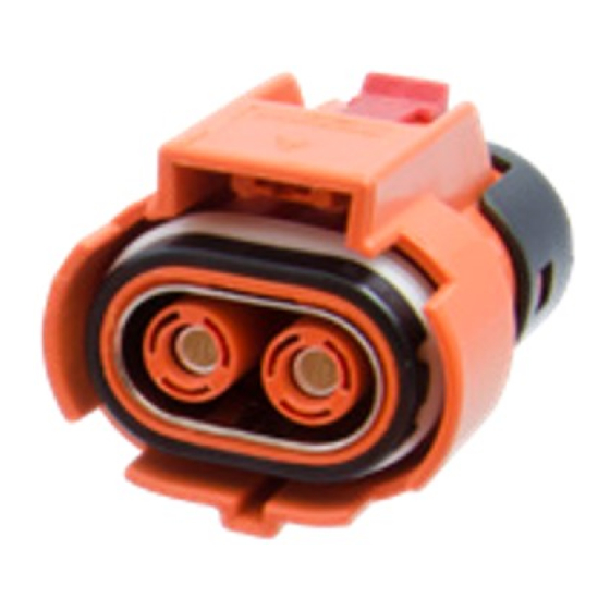
- Page 5 CABLE ASSEMBLY WORK INSTRUCTION ePower lite Mini Series Receptacle Connector...
- Page 6 Part 1: Package Contents Package Contents Receptacle Shell Assembly Power Pin Contact Socket Contact Part 2: Assembly Steps for Power Pin Step 1: wire cutting and stripping jacket dimensions 8± 0.5 mm Step 2: Insert conductor into hole of socket and crimping use right crimping tool Wire Size Recommended Min.
- Page 7 Recommended manual crimping tool as below (P/N: FX3-0094-000): Step 5: Insert the contact with cable assembled into the plug shell, the collar snapped into the shoulder of the hole. Part 3: Assembly Steps for HVIL pin Step 1: Wire cutting and stripping the jacket Step 2: Insert conductor into hole of socket and crimping use right crimping tool Claw...
- Page 8 Recommended HVIL Wire Specification Receptacle HVIL Wire Size Recommended Min. Pullout force (N) 22 AWG 2 ports 20 AWG Recommended Crimping tool as below (P/N: FX3-0095-000): Step 3: Insert the HVIL contacts into the receptacle shell assembly, the claws face to the sides...
Need help?
Do you have a question about the ePower-Lite Mini and is the answer not in the manual?
Questions and answers