Advertisement
Quick Links
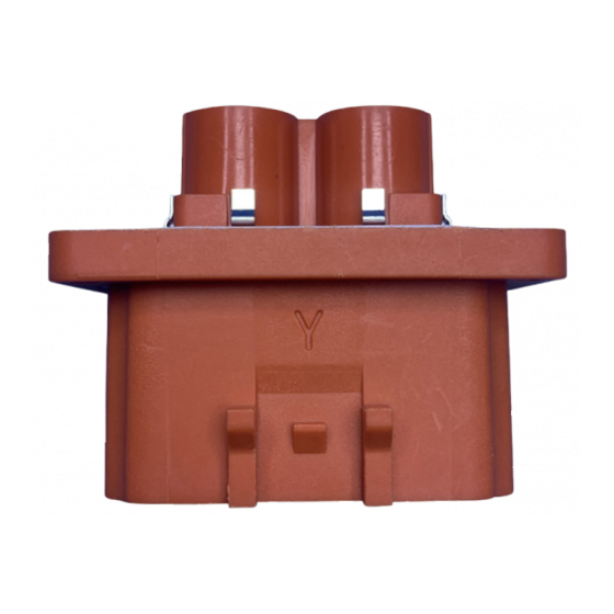
CABLE ASSEMBLY WORK INSTRUCTION
ePower-lite 5.7mm 2 port Connector
Part Numbers:
C10-738986-2XS1
C10-738986-2XS2
Revision
Description
A
lnitial release
B
Change the assembly method of shielding
C
Update picture detail
Part Numbers:
C10-738985-2XP1
C10-738985-2XP2
AI-2
Issue Date
2016/03/10
2019/05/06
2020/05/13
Advertisement

Subscribe to Our Youtube Channel
Related Manuals for Amphenol ePower-lite C10-738986-2XS1


Summary of Contents for Amphenol ePower-lite C10-738986-2XS1
- Page 1 AI-2 CABLE ASSEMBLY WORK INSTRUCTION ePower-lite 5.7mm 2 port Connector Part Numbers: Part Numbers: C10-738986-2XS1 C10-738985-2XP1 C10-738986-2XS2 C10-738985-2XP2 Revision Description Issue Date lnitial release 2016/03/10 Change the assembly method of shielding 2019/05/06 Update picture detail 2020/05/13...
- Page 2 Part 1: Plug Package Contents Package Contents Housing shell assembly (1PCS) Contact assembly (2PCS) Collar (2PCS) Heat shrink tubing (2PCS) Rear shield shell (2PCS) Rear shield ring (2PCS) Rear grommet (1PCS) Rear cover (1PCS) Recommended shielded wire specification Insulation Cable Jacket Recommended Min.
-
Page 3: Plug Assembly
Part 2: Plug Assembly Step 1: Shielded wire stripping the jacket. Item Cutting Length 21±0.5mm Step 2: Assembly the rear shield ring (Part 6). Part 6 Step 3: Cutting shield wire. Item Cutting Length 9±0.5mm... - Page 4 Step 4: Fold back shielding wires onto the rear shield ring. Step 5: Install the Rear Cover (Part 8) and the Rear Grommet (Part 7) in sequence. Mylar Part 7 Part 7 Step 6: Remove film layer, stripping insulation. Item Cutting Length 10.5±0.5mm Step 7:...
- Page 5 Step 9: Install heat shrink tubing to the area where crimping contact and wire. Amphenol P/N: CH53X-005-09A ( Part 4) Notes: Don't let the shrink tubing cover the braid wire Tooling: Heat gun as shown in picture Recommended heat shrink tubing spec: Without hot melt adhesive...
- Page 6 Step 10: Repeat steps 7 and 8 and 9 to assemble another contact assembly. Step 11: Pull one of the wires out and load. Crimp the Rear Shield (Part 5). Recommended crimp length is 3.5±0.5mm length: 24.2 - 25.5mm Recommended crimp Recommended Min.
- Page 7 Step 13: Assembling Collar (part 2) , and Straighten two cable. Part 2 Step 14: Insert the crimped terminal into the Plug shell assembly ( Part 1) one by one. Note that the plane A of the shield and the plane B of the shell are parallel. Flat B Flat A Part 1...
- Page 8 Step 16: lnstall the Rear Cover (Part 8). The rear cover buckle should snap-fit with the main housing shell. Step 17: Requirements for electrical performance testing. Notes: Need to do lnsulation Resistance and DWV test after cable assembly lnsulation Resistance test: 850V DC, 100MΩ Min, 60s DWV test: 2500V AC, leakage current ≤...
- Page 9 Part 3: Receptacle Package Contents Package Contents Receptacle shell assembly (1PCS) Collar (2PCS) Pin contact assembly (2PCS) HVIL socket contact (2PCS) Recommended unshielded wire specification Insulation Recommended Min. Wire Size Diameter (mm) Cable Pullout Force (N) 16 mm 8.1±0.2 1400 25 mm 10.2±0.2 1900...
- Page 10 Step 3: lnstall heat shrink tubing to the area where crimping contact and wire, Then assemble the Collar. Amphenol P/N: CH53X-O05-09A Tooling: Heat gun as shown in picture Recommended heat shrink tubing spec: With hot melt adhesive Excellent sealing and insulation properties Shrink ratio: 2:1 Operating temperature: -55~150°C...
- Page 11 Step 4: lnsert the contact with cable assembled into the plug shell, the collar snapped into the shoulder of the hole. Repeat step 1-4 for another port. Step 5: HVIL wire cutting and stripping the jacket(Recommended use the 20AWG cable). Item Cutting Length 3.5±0.5mm...
- Page 12 Step 7: lnsert the HVIL contact and cable assembly into the plug shell assembly. Step 8: Repeat step 6-8 for another port.
Need help?
Do you have a question about the ePower-lite C10-738986-2XS1 and is the answer not in the manual?
Questions and answers