Table of Contents
Advertisement
Quick Links
Installation, Maintenance & Parts Manual
DORNER MFG. CORP.
P.O. Box 20 • 975 Cottonwood Ave.
Hartland, WI 53029-0020 USA
851-702 Rev. A
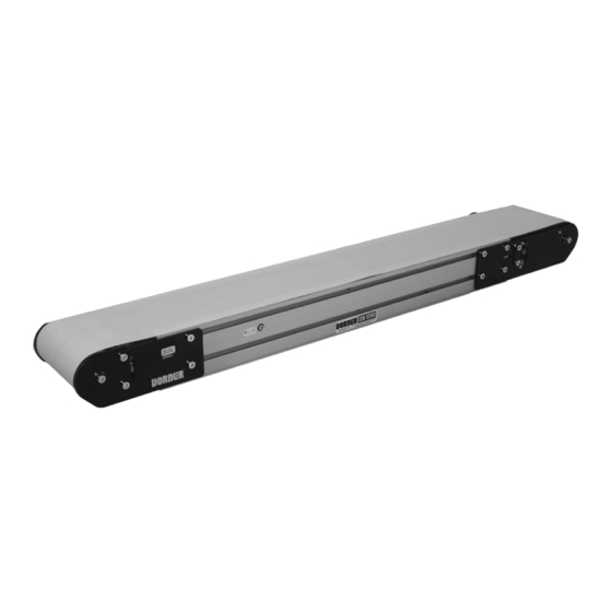
3200 Series iDrive
Belt Conveyors
For other service manuals visit our website at:
www.dorner.com/service_manuals.asp
INSIDE THE USA
TEL: 1-800-397-8664
FAX: 1-800-369-2440
OUTSIDE THE USA
TEL: 262-367-7600
FAX: 262-367-5827
Advertisement
Table of Contents

Related Manuals for Dorner iDrive 3200 Series


Summary of Contents for Dorner iDrive 3200 Series
- Page 1 3200 Series iDrive Belt Conveyors Installation, Maintenance & Parts Manual DORNER MFG. CORP. INSIDE THE USA OUTSIDE THE USA P.O. Box 20 • 975 Cottonwood Ave. TEL: 1-800-397-8664 TEL: 262-367-7600 Hartland, WI 53029-0020 USA FAX: 1-800-369-2440 FAX: 262-367-5827 For other service manuals visit our website at: www.dorner.com/service_manuals.asp...
-
Page 2: Table Of Contents
A − Idler Pulley Removal........... 16 B − Transfer Tail Pulley Removal ......17 Pulley Replacement ............18 Idler Pulley ..............18 Transfer Tail Pulley............ 18 Drive Spindle Removal and Replacement ..... 18 3200 Series iDrive Belt Conveyors Dorner Mfg. Corp. 851-702 Rev. A... -
Page 3: Introduction
6,971,509B2, and corresponding patents and patent DO NOT operate equipment without guards. applications in other countries. Upon receipt of shipment: Dorner reserves the right to make changes at any time without notice or obligation. • Compare shipment with packing slip. Contact factory regarding discrepancies. -
Page 4: Product Description
4 = V-guided Belt, conveyor not to include mounting brackets 3 = Non-V-guided Belt, conveyor not to include mounting brackets 4 = V-guided Belt, conveyor not to include mounting brackets * See Ordering and Specifications Catalog for details. 3200 Series iDrive Belt Conveyors Dorner Mfg. Corp. 851-702 Rev. A... -
Page 5: Conveyor Supports
21-133 Ft./Min., Medium Speed 15-80 Ft./Min., Low Speed Duty Cycle Continuous Rated Continuous Rated Continuous Rated Index Capacity 30 times / Min. 30 times / Min. 30 times / Min. 3200 Series iDrive Belt Conveyors 851-702 Rev. A Dorner Mfg. Corp. -
Page 6: Installation
Conveyors Up to 13 ft (3962 mm) No assembly is required. Install mounting brackets and return rollers. Refer to “Mounting Brackets” on page 7 and Figure 6 “Return Rollers” on page 8. 3200 Series iDrive Belt Conveyors Dorner Mfg. Corp. 851-702 Rev. A... -
Page 7: Mounting Brackets
(Figure 10, item 1) before proceeding to step 5. The zero mark for the tension indicator is when the indicator begins to turn black. Figure 12 3200 Series iDrive Belt Conveyors 851-702 Rev. A Dorner Mfg. Corp. -
Page 8: Return Rollers
14 & Figure 15. Install roller assembly as shown (Figure 18, item 1). Tighten screws (Figure 18, item 2) to 60 in-lb (7 Nm). Figure 14 Figure 18 Figure 14 Figure 18 3200 Series iDrive Belt Conveyors Dorner Mfg. Corp. 851-702 Rev. A... -
Page 9: Wiring
See “Change Acceleration / Deceleration Settings” on page 11 for changing factory control settings. Figure 19 See “Change Acceleration / Deceleration Settings” on page 11 for changing factory control settings. 3200 Series iDrive Belt Conveyors 851-702 Rev. A Dorner Mfg. Corp. -
Page 10: Customer Wired With Flying Leads
1. Start Stop Application: Maximum start stop cycles are 20 per minute. 2. Reversing Applications: Do not reverse the motor direction when running. Make sure the motor is stopped before reversing signal is given. 3200 Series iDrive Belt Conveyors Dorner Mfg. Corp. 851-702 Rev. A... -
Page 11: Potentiometers
Remove control board mounting screws (Figure 22, item 1) from bottom of plate. Figure 23 Figure 22 Reinstall by reversing steps. Figure 22 Locate potentiometers to change. See Controller Board layout on page 10. 3200 Series iDrive Belt Conveyors 851-702 Rev. A Dorner Mfg. Corp. -
Page 12: Preventive Maintenance And Adjustment
• Clean entire conveyor and knurled pulley while disassem- bled Use Dorner Belt Cleaner (part # 625619). Mild soap and water may also be used. Do not soak the belt. • Replace worn or damaged parts For /05 woven polyester and /06 black anti-static belts, use a Lubrication bristled brush to improve cleaning. -
Page 13: Belt Removal For Conveyor Without Stands
Remove conveyor belt. Figure 29 Belt Removal for Conveyor With Stands Place temporary support stands (Figure 26, item 1) at both ends of the conveyor. Figure 26 Figure 29 Figure 26 3200 Series iDrive Belt Conveyors 851-702 Rev. A Dorner Mfg. Corp. -
Page 14: Belt Installation For Conveyor Without Stands
Re-install conveyor mounting brackets. Refer “Mounting Brackets” on page 7, steps 3 through 5. Tension belt. Refer to “Conveyor Belt Tensioning” on page 14. If equipped, re-install return rollers and guiding. Figure 33 3200 Series iDrive Belt Conveyors Dorner Mfg. Corp. 851-702 Rev. A... -
Page 15: Conveyor Belt Tracking
35). See steps below in “Non V-guided Belts” procedure for adjusting for any belt bulging. Belt bulge will be minimal when belt is properly tracked. Figure 35 Figure 37 Figure 35 3200 Series iDrive Belt Conveyors 851-702 Rev. A Dorner Mfg. Corp. -
Page 16: Pulley Removal
Belt Replacement” on page 12. Remove the desired pulley following the corresponding instructions below: • A − Idler Pulley Removal • B − Transfer Tail Pulley Removal Figure 42 3200 Series iDrive Belt Conveyors Dorner Mfg. Corp. 851-702 Rev. A... -
Page 17: B − Transfer Tail Pulley Removal
Slide the shaft assembly (Figure 45, item 1) out of the Figure 47 pulley (Figure 45, item 2). Remove the inner spacer (Figure 48, item 1). Figure 45 Figure 48 Figure 48 Figure 45 3200 Series iDrive Belt Conveyors 851-702 Rev. A Dorner Mfg. Corp. -
Page 18: Pulley Replacement
Figure 51 Remove pulleys (Figure 52, item 1) and additional washers (Figure 52, item 2). Figure 52 Figure 53 Figure 52 To remove additional pulleys, repeat steps 6 through 7. 3200 Series iDrive Belt Conveyors Dorner Mfg. Corp. 851-702 Rev. A... - Page 19 Figure 55 Figure 55 Slide drive motor and plate (Figure 56, item 1) to loosen tension on timing belt (Figure 56, item 2). Figure 58 Figure 56 Figure 56 3200 Series iDrive Belt Conveyors 851-702 Rev. A Dorner Mfg. Corp.
-
Page 20: Replacement
Figure 61 Figure 61 Remove tie strap (Figure 61, item 2) from drive motor harness. If applicable, remove black cap from end (Figure 61, item 3) of drive motor. 3200 Series iDrive Belt Conveyors Dorner Mfg. Corp. 851-702 Rev. A... - Page 21 Figure 63 Loosen two set screws (Figure 64, item 1) holding drive motor gear (Figure 64, item 2) onto drive motor shaft. Figure 64 Figure 64 3200 Series iDrive Belt Conveyors 851-702 Rev. A Dorner Mfg. Corp.
-
Page 22: Circuit Board Removal And Replacement
NOTE Make sure the cord or wires are not across the circuit board when reassembling. Tuck wires and cable into the frame extrusion. Reinstall in reverse order of removal. 3200 Series iDrive Belt Conveyors Dorner Mfg. Corp. 851-702 Rev. A... -
Page 23: Idrive Motor Tuning
GAIN = 100% (4:00 position) MAX = 0% (8:00 position) MIN = 20% (9:00 position) ACCEL = 20% (9:00 position) DECEL = 0% (8:00 position) Speed Pot = 100% (Fully CW) 3200 Series iDrive Belt Conveyors 851-702 Rev. A Dorner Mfg. Corp. -
Page 24: Switch Removal And Replacement
Figure 74 Figure 72 Replace switch assembly. NOTE Make sure the cord or wires are not kinked or under any conveyor parts when reassembling. Reinstall in reverse order of removal. 3200 Series iDrive Belt Conveyors Dorner Mfg. Corp. 851-702 Rev. A... -
Page 25: Notes
Notes 3200 Series iDrive Belt Conveyors 851-702 Rev. A Dorner Mfg. Corp. -
Page 26: Service Parts
Service Parts NOTE For replacement parts other than those shown in this section, contact an authorized Dorner Service Center or the factory. Key Service Parts and Kits are identified by the Performance Parts Kits logo . Dorner recommends keeping these parts on hand. - Page 27 819-028 Fuse 819-150 Fuse Holder 831-140 Power Supply 818-164 Cord DC Power Plug 805-1316 350104 Custom Wired Version WW = Conveyor width reference: 06 to 24 in 02 increments 3200 Series iDrive Belt Conveyors 851-702 Rev. A Dorner Mfg. Corp.
-
Page 28: Idler End Assembly
Idler Spindle Kit (includes items 4 and 7) 32TT3−WW Tail Assembly (including items 1 through 4, 6, 7 and 12) WW = Conveyor width reference: 06 − 24 in 02 increments 3200 Series iDrive Belt Conveyors Dorner Mfg. Corp. 851-702 Rev. A... -
Page 29: Transfer Tail Assembly
3217WW 1” Idler Tail Axle Shaft WW = Conveyor width reference: 06 − 24 in 02 increments 3219WW Support Bar 3237WW Transfer Tail Roller 807−1136 Washer 807−1151 Retaining Ring 3200 Series iDrive Belt Conveyors 851-702 Rev. A Dorner Mfg. Corp. -
Page 30: Frame Assembly
6” 4” (102mm) 300889−LLLLL 22” 4” 4” 4” 4” 6” (152mm) 300890−LLLLL 24” 4” 4” 6” 4” 4” LLLLL = Bed Plate Length (see Bed Plate & Frame Formulas 3200 Series iDrive Belt Conveyors Dorner Mfg. Corp. 851-702 Rev. A... -
Page 31: 04 3" (76Mm) Aluminum Side
17’4” End Drive Conveyor with Standard Tails Conveyor Length = 1733 Tail Factor = 00200 (1733 − 0100) # of Sections (round up)= = 1.36 = 2 Sections 1200 (1733 x 12) − 00200 LLLLL 3200 Series iDrive Belt Conveyors 851-702 Rev. A Dorner Mfg. Corp. -
Page 32: 05 1.5" (38Mm) Aluminum Side
17’4” End Drive Conveyor with Standard Tails Conveyor Length = 1733 Tail Factor = 00200 (1733 − 0100) # of Sections (round up)= = 1.36 = 2 Sections 1200 (1733 x 12) − 00200 LLLLL 3200 Series iDrive Belt Conveyors Dorner Mfg. Corp. 851-702 Rev. A... -
Page 33: −07 Low To Side Wiper
17’4” End Drive Conveyor with Standard Tails Conveyor Length = 1733 Tail Factor = 00200 (1733 − 0100) # of Sections (round up)= = 1.36 = 2 Sections 1200 (1733 x 12) − 00200 LLLLL 3200 Series iDrive Belt Conveyors 851-702 Rev. A Dorner Mfg. Corp. -
Page 34: −09 Low To High Side
17’4” End Drive Conveyor with Standard Tails Conveyor Length = 1733 Tail Factor = 00200 (1733 − 0100) # of Sections (round up)= = 1.36 = 2 Sections 1200 (1733 x 12) − 00200 LLLLL 3200 Series iDrive Belt Conveyors Dorner Mfg. Corp. 851-702 Rev. A... -
Page 35: −10.5" (13Mm) Extruded Plastic
17’4” End Drive Conveyor with Standard Tails Conveyor Length = 1733 Tail Factor = 00200 (1733 − 0100) # of Sections (round up)= = 1.36 = 2 Sections 1200 (1733 x 12) − 00200 LLLLL 3200 Series iDrive Belt Conveyors 851-702 Rev. A Dorner Mfg. Corp. -
Page 36: −13 Adjustable Guiding
Aluminum Profile Guide 10’ (3048mm) 920616M Socket Head Screw M6 x 16mm 202992 Aluminum Profile Guide 11’ (3353mm) 202993 Aluminum Profile Guide 12’ (3658mm) 202994 Aluminum Profile Guide 13’ (3962mm) 3200 Series iDrive Belt Conveyors Dorner Mfg. Corp. 851-702 Rev. A... -
Page 37: −14 Tool-Less Adjustable Guiding
Extruded Guide 202027M Vertical Mounting Guide Shaft LLLLL = Length in inches with 2 decimal places. 202028M Horizontal Mounting Guide Shaft Length Example: Length = 95.25" LLLLL = 09525 3200 Series iDrive Belt Conveyors 851-702 Rev. A Dorner Mfg. Corp. -
Page 38: 0.5" (13Mm) Cleated Guiding
17’4” End Drive Conveyor with Standard Tails Conveyor Length = 1733 Tail Factor = 00200 (1733 − 0100) # of Sections (round up)= = 1.36 = 2 Sections 1200 (1733 x 12) − 00200 LLLLL 3200 Series iDrive Belt Conveyors Dorner Mfg. Corp. 851-702 Rev. A... -
Page 39: 1" (25Mm) Cleated Guiding
17’4” End Drive Conveyor with Standard Tails Conveyor Length = 1733 Tail Factor = 00200 (1733 − 0100) # of Sections (round up)= = 1.36 = 2 Sections 1200 (1733 x 12) − 00200 LLLLL 3200 Series iDrive Belt Conveyors 851-702 Rev. A Dorner Mfg. Corp. -
Page 40: 2" (51Mm) Cleated Guiding
Conveyor Length = 1733 Tail Factor = 00200 (1733 − 0100) # of Sections (round up)= = 1.36 = 2 Sections 1200 (1733 x 12) − 00200 LLLLL Figure 75 3200 Series iDrive Belt Conveyors Dorner Mfg. Corp. 851-702 Rev. A... -
Page 41: Flared Side Guiding
(1219mm) 910506M Button Head Screw M5 x 6mm 202215 Side−Flare Mounting Guide 5’ 911−512 Washer (1524mm) 920694M Cap Low−Head Screw M6 x 20mm 202216 Side−Flare Mounting Guide 6’ (1829mm) 3200 Series iDrive Belt Conveyors 851-702 Rev. A Dorner Mfg. Corp. -
Page 42: Flat Belt Mounting Brackets
Square Nut M6 5mm x 10mm 240836 Cleated Mounting Assembly 920620M Socket Head Screw M6 x 20mm 300150M Drop−In Tee Bar 920692M Socket Head Screw M6 x 12mm 605279P Washer 3200 Series iDrive Belt Conveyors Dorner Mfg. Corp. 851-702 Rev. A... -
Page 43: Connecting Assembly Without Stand Mount
Square Nut M6 5mm x 10mm 240858 Frame Connector Bar 920620M Socket Head Screw M6 x 20mm 240837 Stand Mount Joint 920692M Socket Head Screw M6 x 12mm 605279P Washer 3200 Series iDrive Belt Conveyors 851-702 Rev. A Dorner Mfg. Corp. -
Page 44: Cleated Belt Connecting Assembly With Stand Mount
Socket Low Head Screw M6 x 16mm 240825 240840 Roller Assembly (Includes Items 1, 3 240827 Return Roller Clip and 4) 802−027 Bearing 240830 Flat Belt Return Roller Assy 913−100 Dowel Pin 3200 Series iDrive Belt Conveyors Dorner Mfg. Corp. 851-702 Rev. A... -
Page 45: 8" (203Mm) To 24" (610Mm) Flat Belt Return Roller
Socket Low Head Screw M6 x 16mm 240825 240840 Roller Assembly (Includes Items 1, 3 240828 Cleated Return Roller Clip and 4) 802−027 Bearing 240832 Cleated Belt Return Roller Assembly 913−100 Dowel Pin 3200 Series iDrive Belt Conveyors 851-702 Rev. A Dorner Mfg. Corp. -
Page 46: Conveyor Belt Part Number Configuration
Figure 76 Cleated Belt Part Number Configuration Flat Belt Part Number Configuration Refer to Dorner patent plate (Figure 76). From the model Refer to Dorner patent plate (Figure 76). From the model number determine, cleated belt (“T”), width (“WW”), length number, determine tail type (“T”), width (“WW”), length... -
Page 47: Notes
Notes 3200 Series iDrive Belt Conveyors 851-702 Rev. A Dorner Mfg. Corp. -
Page 48: Return Policy
RMA will automatically close 30 days after being issued. To get credit, items must be new and undamaged. There will be a return charge on all items returned for credit, where Dorner was not at fault. It is the customer’s responsibility to prevent damage during return shipping.
Need help?
Do you have a question about the iDrive 3200 Series and is the answer not in the manual?
Questions and answers