Chapters
Table of Contents

Related Manuals for Dorner FlexMove FC


Summary of Contents for Dorner FlexMove FC
- Page 1 FlexMove FC (105 mm) Conveyor System Installation, Maintenance & Parts Manual For other service manuals visit our website at: www.dornerconveyors.com/manuals-literature Record Conveyor Serial Number Here 851-899 Rev. A...
-
Page 2: Table Of Contents
Nylon Screw ............... 18 Drive Unit............... 36 Aluminum Rivet............19 Checking Slide Rail and Rivet Condition After Fixed .. 19 Joining Chain End............19 Chain Installation at Drive Unit........20 FlexMove FC (105 mm) Conveyor System Dorner Mfg. Corp. 851-899 Rev. A... - Page 3 Type L - Adjustable Height Guiding (18x110) ....81 Type M - Adjustable Height Guiding (18x150) ..... 81 Type N - Fully Adjustable Guiding........ 82 Type P - Fully Adjustable Guiding ........ 82 FlexMove FC (105 mm) Conveyor System 851-899 Rev. A Dorner Mfg. Corp.
-
Page 4: Introduction
DO NOT operate equipment manual with the Performance Parts Kits logo without guards. Dorner reserves the right to make changes at any time without notice or obligation. Upon receipt of shipment: • Compare shipment with packing slip. Contact factory regarding discrepancies. -
Page 5: Warnings − General Safety
ADJUSTMENT SCREWS. Exposed moving parts can cause severe injury. LOCK OUT POWER before removing guards or performing maintenance. A WARNING Gearmotors may be HOT. DO NOT TOUCH Gearmotors. FlexMove FC (105 mm) Conveyor System 851-899 Rev. A Dorner Mfg. Corp. -
Page 6: Product Description
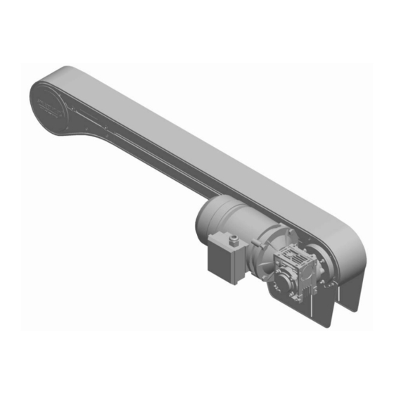
Product Description Refer to Figure 1 for typical components. Infeed Module Curve Module Incline Module Decline Module Intermediate Module Drive Module Gearmotor Stands Figure 1 Figure 1 FlexMove FC (105 mm) Conveyor System Dorner Mfg. Corp. 851-899 Rev. A... -
Page 7: Specifications
3 = 914 mm (36") * For conveyors longer than 3000 mm (118"), install support at joint. Note: Additional support required on 180° curve modules. Figure 2 Figure 2 FlexMove FC (105 mm) Conveyor System 851-899 Rev. A Dorner Mfg. Corp. -
Page 8: Installation
End Drive Unit The chain slack of a normal direct drive unit must be maintained during the system lifetime. FlexMove FC (105 mm) Conveyor System Dorner Mfg. Corp. 851-899 Rev. A... -
Page 9: Hand Tools
Connecting strips (Figure 6) are used for joining end to end Figure 3 of beams. Use hex key and set screws when attaching the connecting strip to the beam. Figure 6 Figure 6 Figure 3 FlexMove FC (105 mm) Conveyor System 851-899 Rev. A Dorner Mfg. Corp. -
Page 10: T-Bolt
If burrs are evident, they must be removed prior to assembly. different feet and beam support brackets, so check which Make sure the cut is straight for proper assembly. ones are suitable to use in your application. FlexMove FC (105 mm) Conveyor System Dorner Mfg. Corp. 851-899 Rev. A... -
Page 11: Foot Installation
Tighten the screws using a wrench (Figure 13, item 1). Figure 10 Figure 13 Slide the connecting strips (Figure 11, item 1) into the structural beam T-slots. Figure 11 Figure 13 Figure 11 FlexMove FC (105 mm) Conveyor System 851-899 Rev. A Dorner Mfg. Corp. -
Page 12: Conveyor Installation
(Figure 17, item 2) as shown in the drawing. Vertical beam support brackets (Figure 15, item 1) are used with vertical support beams and are made from aluminum. Figure 17 Figure 15 Figure 17 Figure 15 FlexMove FC (105 mm) Conveyor System Dorner Mfg. Corp. 851-899 Rev. A... -
Page 13: Conveyor Beam Installation
(Figure 20, item 1). Pull the second bracket up and insert the T-bolts into the conveyor beam T-slot. Tighten the nuts. Figure 20 Figure 22 Figure 20 FlexMove FC (105 mm) Conveyor System 851-899 Rev. A Dorner Mfg. Corp. -
Page 14: Drive Unit And Idler End Unit Installation
Insert the idler unit (Figure 27, item 1) connecting Figure 24 strips into the T-slots of the beam end and tighten it. Figure 27 Figure 24 Figure 27 FlexMove FC (105 mm) Conveyor System Dorner Mfg. Corp. 851-899 Rev. A... -
Page 15: Attaching Slide Rail In Straight Beam
(Figure 29, item 1). Separate the top and bottom flange of the slide rail at the end of rail and press into place. Figure 29 Wrong Installation Figure 29 Figure 31 FlexMove FC (105 mm) Conveyor System 851-899 Rev. A Dorner Mfg. Corp. -
Page 16: Slide Rail End Installation At Connector Beam
Allow a space of approximately 10 mm (Figure 34, item 1) between two slide rail ends. The travel direction is indicated by an arrow. Figure 34 Figure 34 FlexMove FC (105 mm) Conveyor System Dorner Mfg. Corp. 851-899 Rev. A... -
Page 17: Slide Rail Installation At Wheel Bend
In the outer bend, make sure that the slide rail is the slide rail. properly connected to the conveyor beam profile. Figure 40 Figure 38 Figure 40 Figure 38 FlexMove FC (105 mm) Conveyor System 851-899 Rev. A Dorner Mfg. Corp. -
Page 18: Fixing Slide Rail
Figure 42 Figure 44 NOTE Nylon screws can be used multiple times before being discarded. Ensure bottom of screw is cut square before re-using. Figure 42 FlexMove FC (105 mm) Conveyor System Dorner Mfg. Corp. 851-899 Rev. A... -
Page 19: Aluminum Rivet
Check both top and underneath surface of Figure 50 slide rail for protruding metal. (See Figure 47.) Figure 47 Correct Wrong Figure 47 Figure 50 FlexMove FC (105 mm) Conveyor System 851-899 Rev. A Dorner Mfg. Corp. -
Page 20: Chain Installation At Drive Unit
(Figure 56, item 1) at the hole provided at drive unit and join the chain. Figure 56 Figure 52 Figure 53 Figure 53 Figure 56 FlexMove FC (105 mm) Conveyor System Dorner Mfg. Corp. 851-899 Rev. A... -
Page 21: Chain Assembly At Chain Disconnecting Module Fccc
60, item 1) to put the chain back together again. Remove the flange (Figure 58, item 1) so that the chain Figure 60 becomes accessible. Figure 58 Figure 60 Figure 58 FlexMove FC (105 mm) Conveyor System 851-899 Rev. A Dorner Mfg. Corp. -
Page 22: Weighted Take-Up
• For standard belt use these holes (Figure 65, item 1). • For friction insert belt use these holes (Figure 65, item 2). Figure 65 Figure 62 Figure 65 FlexMove FC (105 mm) Conveyor System Dorner Mfg. Corp. 851-899 Rev. A... -
Page 23: Top Running Drive
Insert the belt rod. Use a punch and hammer or belt removal tool #203480 (Figure 67, item 2) to press pin just below flush with side of belt. Stop when pin detent is felt. Figure 70 FlexMove FC (105 mm) Conveyor System 851-899 Rev. A Dorner Mfg. Corp. -
Page 24: Install Guiding
If brackets are spaced at greater distances than allow easy access for the conveyor chain pin insertion 1000 mm, there is a possibility that guide rails will become tool. deformed due to excessive force. FlexMove FC (105 mm) Conveyor System Dorner Mfg. Corp. 851-899 Rev. A... -
Page 25: High Side Guiding
Figure 76 Figure 76 Figure 74 NOTE Be certain that slot (Figure 74, item 3) is close to vertical when finished tightening nut. Tighten nuts (Figure 74, item 2). FlexMove FC (105 mm) Conveyor System 851-899 Rev. A Dorner Mfg. Corp. - Page 26 (Figure 78, item 2) to remove clip (Figure 79, item 1). Figure 81 Figure 78 Figure 78 Figure 81 Adjust rail width with top screw (Figure 82, item 1). Figure 79 Figure 82 Figure 79 Figure 82 FlexMove FC (105 mm) Conveyor System Dorner Mfg. Corp. 851-899 Rev. A...
-
Page 27: Puck/Pallet Guiding
Fasten clip (Figure 84, item 1) to conveyor with nut (Figure 84, item 3) on stud. FlexMove FC (105 mm) Conveyor System 851-899 Rev. A Dorner Mfg. Corp. -
Page 28: Adjustable Guide Rail Bracket
Figure 89 Use a wrench (Figure 89, item 4) to tighten the guide rail to the frame. Remember, do not over tighten the screw. Install remaining brackets. FlexMove FC (105 mm) Conveyor System Dorner Mfg. Corp. 851-899 Rev. A... -
Page 29: Fgrf- 42X18V Guide Rail Bracket Assembly
Attach the bracket onto conveyor beam and tighten with a socket wrench (Figure 93, item 1). Figure 93 Figure 95 Option 3 Figure 96 Figure 93 Figure 96 FlexMove FC (105 mm) Conveyor System 851-899 Rev. A Dorner Mfg. Corp. -
Page 30: Fgrf- 42X18V Spacer Assembly
Figure 99 Attach the bracket onto conveyor beam and tighten with a socket wrench (Figure 100, item 1). Install upper and lower caps. Figure 100 Figure 98 Figure 100 FlexMove FC (105 mm) Conveyor System Dorner Mfg. Corp. 851-899 Rev. A... -
Page 31: Assembly With Different Guide Rail Support
Install both caps of the bracket. Figure 104 Figure 102 Figure 104 NOTE Tighten all the screws when the position is justified. Remember to assemble the upper and lower caps onto the bracket. FlexMove FC (105 mm) Conveyor System 851-899 Rev. A Dorner Mfg. Corp. -
Page 32: Fixed Guide Rail Bracket Installation
Figure 108 Figure 108 Connecting Plug Figure 106 Connecting plugs (Figure 109, item 1) are pressed into two guide rail ends with soft hammer. Figure 109 Figure 109 FlexMove FC (105 mm) Conveyor System Dorner Mfg. Corp. 851-899 Rev. A... -
Page 33: Guide Rail Cover Installation
Instability of the conveyor during operation may result in a dangerous operating environment or damage the conveyor components. FlexMove FC (105 mm) Conveyor System 851-899 Rev. A Dorner Mfg. Corp. -
Page 34: Safeguarding Can Be Achieved By
Bushing • Mechanical parts may wear depending on Pressure Plate the rotation speed and slipping time. Check the operation periodically. Disk Spring Lock Washer Pilot Plate Adjustable Bolt FlexMove FC (105 mm) Conveyor System Dorner Mfg. Corp. 851-899 Rev. A... -
Page 35: Preventive Maintenance And Adjustment
Try to minimize the running time for the conveyor by stopping it when there is no transport. Multiple horizontal and vertical plain bends in a conveyor will often result in increased wear. FlexMove FC (105 mm) Conveyor System 851-899 Rev. A Dorner Mfg. Corp. -
Page 36: Inspection
• Check that the nylon screw is in place and does not pro- trude over the surface of the slide rail. • Check that the joint sections are not deformed. FlexMove FC (105 mm) Conveyor System Dorner Mfg. Corp. 851-899 Rev. A... -
Page 37: Checks When The Chain Is Removed
(Figure 117). Figure 117 Figure 117 • Check that the chain cover is in place for the conveyor chain on the intermediate drive units and the catenary drive units. FlexMove FC (105 mm) Conveyor System 851-899 Rev. A Dorner Mfg. Corp. -
Page 38: Troubleshooting
• Review belt and repair or replace as required. • Accumulation of conveyed material • Remove chain and clean out. or foreign objects inside of casing. FlexMove FC (105 mm) Conveyor System Dorner Mfg. Corp. 851-899 Rev. A... -
Page 39: Required Tools
Replacing a Section or Entire Chain Use chain removal tool or a punch and hammer to push the chain rod (Figure 118, item 1) out. Figure 118 Figure 118 FlexMove FC (105 mm) Conveyor System 851-899 Rev. A Dorner Mfg. Corp. -
Page 40: Conveyor Chain Tensioning
A WARNING Exposed moving parts can cause severe Figure 119 injury. LOCK OUT POWER before removing guards or performing maintenance. Remove chain. See “Conveyor Chain Replacement” on page 39. FlexMove FC (105 mm) Conveyor System Dorner Mfg. Corp. 851-899 Rev. A... -
Page 41: Drive Spindle Shaft Replacement
Remove four screws (Figure 125, item 1) on side of head plate assembly. drive spindle. Figure 123 Figure 125 Figure 125 Figure 123 Install components reverse of removal. FlexMove FC (105 mm) Conveyor System 851-899 Rev. A Dorner Mfg. Corp. -
Page 42: Retaining Guide Replacement
Remove three socket head screws (Figure 130, item 1) and remove drive plate guard (Figure 130, item 2) from drive plate (Figure 130, item 3). Figure 130 Figure 127 Figure 128 Figure 130 Figure 128 FlexMove FC (105 mm) Conveyor System Dorner Mfg. Corp. 851-899 Rev. A... -
Page 43: Idler End And Gp Drive Tail
Remove retaining guide (Figure 136, item 1) from idler Figure 133 head plate assembly (Figure 136, item 2). Replace components, as needed. Figure 136 Figure 133 Figure 136 Install components reverse of removal. FlexMove FC (105 mm) Conveyor System 851-899 Rev. A Dorner Mfg. Corp. -
Page 44: Top Running Drive
Remove four socket head screws (Figure 139, item 1) securing belt hold down tabs (Figure 139, item 2) to drive assembly (Figure 139, item 3). Figure 139 Figure 141 Figure 139 Repeat on opposite side. FlexMove FC (105 mm) Conveyor System Dorner Mfg. Corp. 851-899 Rev. A... -
Page 45: Wheel Bend Servicing
12. Remove four low head cap screws securing spindle assembly to side plate on the opposite side. 13. Replace spindle assembly. Figure 145 Replace wheel guide. Install components reverse of removal. FlexMove FC (105 mm) Conveyor System 851-899 Rev. A Dorner Mfg. Corp. -
Page 46: Weighted Take-Up
149, item 2), two spacers (Figure 149, item 3), and wheel (Figure 149, item 4) from take up assembly housing (Figure 149, item 5). Figure 149 Figure 147 Figure 149 FlexMove FC (105 mm) Conveyor System Dorner Mfg. Corp. 851-899 Rev. A... - Page 47 152, item 2), spacer (Figure 152, item 3), wave washer (Figure 152, item 4), and plate (Figure 152, item 5) from end of idler assembly (Figure 152, item 6). Figure 152 Figure 154 Figure 152 FlexMove FC (105 mm) Conveyor System 851-899 Rev. A Dorner Mfg. Corp.
-
Page 48: Power Transfer
Slide idler assembly within slot (Figure 158, item 2) to remove tension on belt. Remove two socket head screws (Figure 159, item 1) and pinch guard (Figure 159, item 2). Figure 159 Figure 156 Figure 159 FlexMove FC (105 mm) Conveyor System Dorner Mfg. Corp. 851-899 Rev. A... - Page 49 Figure 161 power transfer. Figure 163 Figure 161 Figure 163 NOTE Note that head of pin (Figure 161, item 1) should be removed in direction shown. Remove belt. FlexMove FC (105 mm) Conveyor System 851-899 Rev. A Dorner Mfg. Corp.
- Page 50 Figure 165 Figure 167 Figure 165 13. Replace idler assembly (if worn), and install socket head screws to secure. FlexMove FC (105 mm) Conveyor System Dorner Mfg. Corp. 851-899 Rev. A...
-
Page 51: Installation
(Figure 169, item 2) and press outward as shown. Figure 169 Figure 169 Figure 171 Tighten sprocket with set screws (Figure 171, item 3) in proper alignment with belt (Figure 171, item 1). FlexMove FC (105 mm) Conveyor System 851-899 Rev. A Dorner Mfg. Corp. - Page 52 (Figure 175, item 2). with belt routing under gear (Figure 173, item 2) and over wear tube (Figure 173, item 3). Figure 175 Figure 173 Figure 175 Figure 173 FlexMove FC (105 mm) Conveyor System Dorner Mfg. Corp. 851-899 Rev. A...
- Page 53 Figure 179 12. Install cover (Figure 180, item 1) with two socket head screws (Figure 180, item 2). Figure 180 Figure 177 11. Install timing belt: Figure 180 FlexMove FC (105 mm) Conveyor System 851-899 Rev. A Dorner Mfg. Corp.
-
Page 54: Service Parts
Service Parts NOTE For replacement parts other than those shown in this section, contact an authorized Dorner distributor or Dorner directly. Recommended Critical Service Parts and Kits are identified by the Key Service Parts symbol . Dorner recommends keeping these parts on hand. - Page 55 Drive Flange for Power Transfer CP1005-1-SF Guard Plate (Pair - with screws) Service parts can be obtained through your distributor or directly from Dorner Mfg. Corp. (800) 397-8664 or customerservice@dorner.com FlexMove FC (105 mm) Conveyor System 851-899 Rev. A Dorner Mfg. Corp.
-
Page 56: Guided Profile (Gp) Drive Tail
Service Parts Guided Profile (GP) Drive Tail 4 Guided Profile Drive Tail Kit Optional Auxiliary Shaft Shown FlexMove FC (105 mm) Conveyor System Dorner Mfg. Corp. 851-899 Rev. A... - Page 57 'D' Position FLG-120-SF Drive Flange 207242 Drive Flange for Power Transfer Service parts can be obtained through your distributor or directly from Dorner Mfg. Corp. (800) 397-8664 or customerservice@dorner.com FlexMove FC (105 mm) Conveyor System 851-899 Rev. A Dorner Mfg. Corp.
-
Page 58: Fcsd-A105 Suspended Drive
Service Parts FCSD-A105 Suspended Drive 7 Suspended Drive Tail Kit FlexMove FC (105 mm) Conveyor System Dorner Mfg. Corp. 851-899 Rev. A... - Page 59 Suspended Guided Profile Drive Tail Kit with Shaft in the ‘D’ Position Service parts can be obtained through your distributor or directly from Dorner Mfg. Corp. (800) 397-8664 or customerservice@dorner.com FlexMove FC (105 mm) Conveyor System 851-899 Rev. A Dorner Mfg. Corp.
-
Page 60: Fcid-Dd-0L1/0R1 Intermediate Direct Drive
FCD Return Steering Guide R/L CP1012-M Return Chain Protector 6205LLU NTN Bearing Service parts can be obtained through your distributor or directly from Dorner Mfg. Corp. (800) 397-8664 or customerservice@dorner.com FlexMove FC (105 mm) Conveyor System Dorner Mfg. Corp. 851-899 Rev. A... -
Page 61: Fcid-Sd-0L1/0R1 Intermediate Suspended Drive
NTN Bearing FATL-250 Sprocket RS08BX19T-20 Transmission Sprocket FRS008B-64LK Roller Chain Service parts can be obtained through your distributor or directly from Dorner Mfg. Corp. (800) 397-8664 or customerservice@dorner.com FlexMove FC (105 mm) Conveyor System 851-899 Rev. A Dorner Mfg. Corp. -
Page 62: Weighted Take-Up
Service Parts Weighted Take-Up FlexMove FC (105 mm) Conveyor System Dorner Mfg. Corp. 851-899 Rev. A... -
Page 63: Item Part Number Description
Weighted Take-Up Disk, 1/4" 207747 Weighted Take-Up Disk, 5/16" 207238 Guide Spacer Service parts can be obtained through your distributor or directly from Dorner Mfg. Corp. (800) 397-8664 or customerservice@dorner.com FlexMove FC (105 mm) Conveyor System 851-899 Rev. A Dorner Mfg. Corp. -
Page 64: Idler Tail
Service Parts Idler Tail 4 Idler Tail Kit Optional Auxiliary Shaft Shown FlexMove FC (105 mm) Conveyor System Dorner Mfg. Corp. 851-899 Rev. A... - Page 65 FCIE-A105PT-R Idler Tail Kit with Shaft in the 'D' Position and Power Transfer Service parts can be obtained through your distributor or directly from Dorner Mfg. Corp. (800) 397-8664 or customerservice@dorner.com FlexMove FC (105 mm) Conveyor System 851-899 Rev. A...
-
Page 66: Top Running Drive
Service Parts Top Running Drive FlexMove FC (105 mm) Conveyor System Dorner Mfg. Corp. 851-899 Rev. A... -
Page 67: From Dorner Mfg. Corp. (800) 397-8664 Or
Low Head Cap Screw, M6-1.00 x 50 mm B6205-C70-T15 Bearing Retainer Service parts can be obtained through your distributor or directly from Dorner Mfg. Corp. (800) 397-8664 or customerservice@dorner.com FlexMove FC (105 mm) Conveyor System 851-899 Rev. A Dorner Mfg. Corp. -
Page 68: Frame Assembly
LLLLL = Part length in inches with two decimal places. Length Example: Length = 95.25" LLLLL = 09525 Service parts can be obtained through your distributor or directly from Dorner Mfg. Corp. (800) 397-8664 or customerservice@dorner.com FlexMove FC (105 mm) Conveyor System Dorner Mfg. -
Page 69: Curve Frame Assembly
Wheel Guide (Pair) A = Curve Angle: 30, 45, 60, 90, 135, 180 Service parts can be obtained through your distributor or directly from Dorner Mfg. Corp. (800) 397-8664 or customerservice@dorner.com FlexMove FC (105 mm) Conveyor System 851-899 Rev. A... -
Page 70: Knuckle Frame Assembly
FCVB-90R4005 90° Knuckle Kit FACS-25x140A Connecting Bracket, w/Set Screws (x10) Service parts can be obtained through your distributor or directly from Dorner Mfg. Corp. (800) 397-8664 or customerservice@dorner.com FlexMove FC (105 mm) Conveyor System Dorner Mfg. Corp. 851-899 Rev. A... -
Page 71: #4 & #5 High Sides For Straight Modules
LLLLL = Part length in inches with two decimal places. Length Example: Length = 95.25" LLLLL = 09525 Service parts can be obtained through your distributor or directly from Dorner Mfg. Corp. (800) 397-8664 or customerservice@dorner.com FlexMove FC (105 mm) Conveyor System 851-899 Rev. -
Page 72: #4 & #5 High Sides For Curve Modules
Hex Nut, M8-1.25 AAA = Angle of curve: 030, 060, 045, 090, 135, 180 Service parts can be obtained through your distributor or directly from Dorner Mfg. Corp. (800) 397-8664 or customerservice@dorner.com FlexMove FC (105 mm) Conveyor System Dorner Mfg. Corp. -
Page 73: #4 & #5 High Sides For Incline/Decline Modules
Spacer AA = Angle of bend: 05, 07, 10, 15, 20, 30, 45, 60, 90 Service parts can be obtained through your distributor or directly from Dorner Mfg. Corp. (800) 397-8664 or customerservice@dorner.com FlexMove FC (105 mm) Conveyor System 851-899 Rev. A... -
Page 74: #13 & #14 Heavy Duty Fully Adjustable Guiding
Length Example: Length = 35.25" LLLLL = 03525 M6-1.00 x 150 mm Service parts can be obtained through your distributor or directly 206697 Knob, 150 mm (Tool-Less) from Dorner Mfg. Corp. (800) 397-8664 or 990601M Hex Nut customerservice@dorner.com FlexMove FC (105 mm) Conveyor System Dorner Mfg. -
Page 75: #17 & #18 - Puck / Pallet Guiding
Guide Rail (per foot) 203825 Clip On Slide Rail (per foot) Service parts can be obtained through your distributor or directly from Dorner Mfg. Corp. (800) 397-8664 or customerservice@dorner.com FlexMove FC (105 mm) Conveyor System 851-899 Rev. A Dorner Mfg. Corp. -
Page 76: Type A - Fixed Guiding (16X54)
Guiding (3 m long) FGRD-6 Spacer (x10) Service parts can be obtained through your distributor or directly FATB-20 T-Bolt, 20 mm, use without spacer (x50) from Dorner Mfg. Corp. (800) 397-8664 or FATB-35 T-Bolt, 35 mm (x50) customerservice@dorner.com 990802M Hex Nut... -
Page 77: Type C - Fixed Guiding (28X42)
Guiding (3 m long) FGRD-6 Spacer (x10) Service parts can be obtained through your distributor or directly FATB-20 T-Bolt, 20 mm, use without spacer (x50) from Dorner Mfg. Corp. (800) 397-8664 or FATB-35 T-Bolt, 35 mm (x50) customerservice@dorner.com 990802M Hex Nut... -
Page 78: Type E - Fixed Guiding (49X42)
Guiding (3 m long) FGRD-6 Spacer (x10) Service parts can be obtained through your distributor or directly FATB-20 T-Bolt, 20 mm, use without spacer (x50) from Dorner Mfg. Corp. (800) 397-8664 or FATB-35 T-Bolt, 35 mm (x50) customerservice@dorner.com 990802M Hex Nut... -
Page 79: Type G - Fixed Guiding (90X42)
Guiding (3 m long) FGRD-6 Spacer (x10) Service parts can be obtained through your distributor or directly FATB-20 T-Bolt, 20 mm, use without spacer (x50) from Dorner Mfg. Corp. (800) 397-8664 or FATB-35 T-Bolt, 35 mm (x50) customerservice@dorner.com 990802M Hex Nut... -
Page 80: Type J - Adjustable Width Guiding (26X39X45)
Guiding (3 m long) FGRD-6 Spacer (x10) Service parts can be obtained through your distributor or directly FATB-20 T-Bolt, 20 mm, use without spacer (x50) from Dorner Mfg. Corp. (800) 397-8664 or FATB-35 T-Bolt, 35 mm (x50) customerservice@dorner.com 990802M Hex Nut... -
Page 81: Type L - Adjustable Height Guiding (18X110)
Guiding (3 m long) FGRD-18A Spacer (x10) Service parts can be obtained through your distributor or directly FGRL-18x110C Guide Rail Support (x10) from Dorner Mfg. Corp. (800) 397-8664 or FATB-20 T-Bolt, 20 mm, use without spacer (x50) customerservice@dorner.com FATB-35 T-Bolt, 35 mm, use with 1 spacer (x50) -
Page 82: Type N - Fully Adjustable Guiding
FGRS-18 Guide Rail Support (x10) Service parts can be obtained through your distributor or directly FGSP-DT Tube Spacer (x10) from Dorner Mfg. Corp. (800) 397-8664 or FGGR-18x100 Guide Rail Tube, 100 mm (x10) customerservice@dorner.com FGGR-18x150 Guide Rail Tube, 150 mm (x10) -
Page 83: Type Q - Dual Rail Guiding
T-Bolt, 53 mm, use with 2 spacers (x50) Service parts can be obtained through your distributor or directly FGRF-A110 Guide Rail Bracket (x10) from Dorner Mfg. Corp. (800) 397-8664 or FGRF-DP Plug (x10) customerservice@dorner.com Type R - Dual Rail Guiding... -
Page 84: Type S - Adjustable Height Guiding
Guide Rail (3 m long) FGRT-3x23 Guiding (3 m long) Service parts can be obtained through your distributor or directly from Dorner Mfg. Corp. (800) 397-8664 or customerservice@dorner.com FlexMove FC (105 mm) Conveyor System Dorner Mfg. Corp. 851-899 Rev. A... -
Page 85: Power Transfer
Cup Set Screw, M6-0.80 x 5 mm Service parts can be obtained through your distributor or directly 205725-105 Tensioner Assembly from Dorner Mfg. Corp. (800) 397-8664 or customerservice@dorner.com FlexMove FC (105 mm) Conveyor System 851-899 Rev. A Dorner Mfg. Corp. -
Page 86: Horizontal Mounting Brackets
M6-1.00 x 22 mm 990602M Hex Nut, M6-1.00 990812M Flanged Hex Nut, M8-1.25 Service parts can be obtained through your distributor or directly from Dorner Mfg. Corp. (800) 397-8664 or customerservice@dorner.com FlexMove FC (105 mm) Conveyor System Dorner Mfg. Corp. 851-899 Rev. A... -
Page 87: Support Post - Conveyor Frame Mount
Length Example: Length = 95.25" LLLLL = 09525 FBFT-64 Stand Foot for 64 mm Stand w/Hardware Service parts can be obtained through your distributor or directly from Dorner Mfg. Corp. (800) 397-8664 or FBFT-80B Stand Foot for 80 mm Stand customerservice@dorner.com w/Hardware... -
Page 88: Support Post - Motor Mount
Length Example: Length = 95.25" LLLLL = 09525 (x10) Service parts can be obtained through your distributor or directly 960882M Flange Head Cap Screw, from Dorner Mfg. Corp. (800) 397-8664 or M8-1.25 x 12 mm customerservice@dorner.com FATB-20 T-Bolt, 20 mm... -
Page 89: Suspended Drive Stand
Length Example: Length = 95.25" LLLLL = 09525 w/Hardware Service parts can be obtained through your distributor or directly FBSB-64X64-LLLLL Leg for 64 mm Stand from Dorner Mfg. Corp. (800) 397-8664 or FBSB-80X80-LLLLL Leg for 80 mm Stand customerservice@dorner.com FlexMove FC (105 mm) Conveyor System 851-899 Rev. -
Page 90: Dual Side Support Post
Cover for 64 mm Stand (x10) Service parts can be obtained through your distributor or directly FBEC-80 Cover for 80 mm Stand (x10) from Dorner Mfg. Corp. (800) 397-8664 or customerservice@dorner.com FlexMove FC (105 mm) Conveyor System Dorner Mfg. Corp. -
Page 91: E-Drive Gearmotor Mounting Package
931025M Flat Head Screw, M10-1.50 x 25 mm 911-108 Washer Service parts can be obtained through your distributor or directly from Dorner Mfg. Corp. (800) 397-8664 or customerservice@dorner.com FlexMove FC (105 mm) Conveyor System 851-899 Rev. A Dorner Mfg. Corp. -
Page 92: Standard Load 90° Industrial Gearmotors
Gear Reducer, 60:1, NEMA 56C 32M010EH Gear Reducer, 10:1, NEMA 140 TC Service parts can be obtained through your distributor or directly from Dorner Mfg. Corp. (800) 397-8664 or customerservice@dorner.com FlexMove FC (105 mm) Conveyor System Dorner Mfg. Corp. 851-899 Rev. A... -
Page 93: Flange Mounted Motor (Direct Drive Tail)
Hand Gearmotor matching RH or LH Drive Note: speed range for 60 Hz gearmotors is 10 to 60 Hz or 6:1. Service parts can be obtained through your distributor or directly from Dorner Mfg. Corp. (800) 397-8664 or customerservice@dorner.com FlexMove FC (105 mm) Conveyor System 851-899 Rev. -
Page 94: Foot Mounted Motor (Suspended Drive Tail)
(X) = L or R for Right Hand o Note: speed range for 60Hz gearmotors is 10 to 60 Hz or 6:1. Service parts can be obtained through your distributor or directly from Dorner Mfg. Corp. (800) 397-8664 or customerservice@dorner.com FlexMove FC (105 mm) Conveyor System Dorner Mfg. -
Page 95: Slide Rail Replacement Tool
5CPC-5M Twist Chain (25 M Roll) Service parts can be obtained through your distributor or FASR-25P Special Abrasive Resistant directly from Dorner Mfg. Corp. (800) 397-8664 or (25 M Roll) customerservice@dorner.com FASR-25T Special Abrasive Resistant, High Load (25 M Roll) -
Page 96: Belt Removal Tool
Description Service parts can be obtained through your distributor or directly 897-1099 Utility Cutter from Dorner Mfg. Corp. (800) 397-8664 or Service parts can be obtained through your distributor or directly customerservice@dorner.com from Dorner Mfg. Corp. (800) 397-8664 or customerservice@dorner.com... -
Page 97: Notes
Notes FlexMove FC (105 mm) Conveyor System 851-899 Rev. A Dorner Mfg. Corp. -
Page 98: Return Policy
Return Policy Returns must have prior written factory authorization or they will not be accepted. Items that are returned to Dorner without authorization will not be credited nor returned to the original sender. When calling for authorization, please have the following information ready for the Dorner factory representative or your local distributor: Name and address of customer.
Need help?
Do you have a question about the FlexMove FC and is the answer not in the manual?
Questions and answers