Table of Contents
Advertisement
Quick Links
Advertisement
Table of Contents

Related Manuals for Cofem COMPACT LYON PLUS


Summary of Contents for Cofem COMPACT LYON PLUS
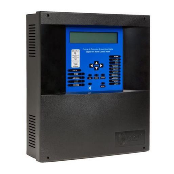
- Page 1 MANUAL Digital fire detection control panel COMPACT LYON PLUS...
-
Page 2: Table Of Contents
Digital fire detection control panel COMPACT LYON PLUS Index 1- System description ................................6 1.1- Introduction ................................6 1.2.- Principle of operation ..............................6 1.3.- Characteristics ................................7 1.4.- Composition of the control panel..........................7 1.5. – Loop Elements Capacity ............................8 1.5.1.- Addressable sensors ( A30 series ) ........................ - Page 3 Digital fire detection control panel COMPACT LYON PLUS 2.4.1.- Computer................................52 3- Operation and configuration............................54 3.1- Description of the front panel..........................54 3.1.1- Keypad................................54 3.1.2.- Light indicators..............................54 3.1.3- LCD..................................55 3.2- Access levels................................55 3.2.1.- Level 1 access.
- Page 4 Digital fire detection control panel COMPACT LYON PLUS 4. Checking the incident ..............................86 5. Evacuation ................................... 87 6. SILENCE SIRENS ................................87 7. RESET EVENTS ................................87 Annex 2: Elements configuration Lyon / C-Lyon / Zafir ....................... 88 1. Introduction ................................. 88 2.
- Page 5 Digital fire detection control panel COMPACT LYON PLUS CERTIFICATION 0099 C/ Compositor Wagner,8 —P.I. Can Jardí CP 08191-- Rubí, Barcelona (España) 10 / 09 0099/CPR/A74/0102 – 0099/CPR/A74/0082 EN 54-2 EN 54-4 Equipo de control e indicación para sistemas de detección y Equipo de suministro de alimentación para sistemas de...
-
Page 6: 1- System Description
With this type of system, not only we can vary the sensitivity of the sensor, but we can even adapt the sensitivity to the environmental conditions. Each sensor on the Cofem Digital Detection System transmits its digital value to the control panel with a regularity of less than 10 seconds. The control panel gathers the readings from each sensor and determines the status thereof according to these instant readings, any previous readings (history), the pre-programmed parameters and on the decision algorithm. -
Page 7: Characteristics
Configurable and manageable through I-Link PC software. Allows connection of up to 15 repeaters and 15 control panels in network. Contact ID (See specific manual of this functionality). Cofem Remote on demand Size: 363 x331 x 96 mm IP30. -
Page 8: Loop Elements Capacity
Digital fire detection control panel COMPACT LYON PLUS Switching Power Supply Display Power supply Figure 1. Layout of circuits in the control panel 1.5. – Loop Elements Capacity The number of devices that it is possible to connect to the loop is calculated by the software of loop elements capacity calculation. - Page 9 Digital fire detection control panel COMPACT LYON PLUS FIRE PROTECTION MANUFACTURER C / Compositor Wagner, 8 –P.I. Can Jardí 08191 - RUBÍ (Barcelona) ESPAÑA. Tlf.: +34 935 862 690 – cofem@cofem.com – www.cofem.com...
- Page 10 Digital fire detection control panel COMPACT LYON PLUS FIRE PROTECTION MANUFACTURER C / Compositor Wagner, 8 –P.I. Can Jardí 08191 - RUBÍ (Barcelona) ESPAÑA. Tlf.: +34 935 862 690 – cofem@cofem.com – www.cofem.com...
-
Page 11: Addressable Sensors ( A30 Series)
Digital fire detection control panel COMPACT LYON PLUS 1.5.1.- Addressable sensors ( A30 series) 1.5.1.1.- Addressable smoke sensors (A30XHA & A30XHA-S) The addressable smoke sensors measure the smoke particle concentration by unit of volume present in the atmosphere. If we designate by Y an un-... -
Page 12: 2.- Addressable Temperature Sensor (A30Xta)
Digital fire detection control panel COMPACT LYON PLUS 1.5.1.2.- Addressable temperature sensor (A30XTA) The Addressable Temperature Sensor (A30XTA) measures the room temperature, as well as its rate of change. When the ambient temperature experiences slow rates of change (less than 1ºC / min), the Alarm level remains constant to 60ºC. -
Page 13: 3.- Addressable Multi-Sensor (A30Xhtco)
Digital fire detection control panel COMPACT LYON PLUS 1.5.1.3.- Addressable multi-sensor (A30XHTCO) The addressable multi-sensor A30XHTCO has three detection types: monoxide, temperature and smoke. The addressable multi-sensors is able to measure three types of parameters so the control panel compute the average by means of a dynamic processing algorithm which will vary with the three phenomena. - Page 14 Digital fire detection control panel COMPACT LYON PLUS Figure 2A. Wiring Diagram of A30XHA, A30XTA, A30XHTCO and PUCAY devices FIRE PROTECTION MANUFACTURER C / Compositor Wagner, 8 –P.I. Can Jardí 08191 - RUBÍ (Barcelona) ESPAÑA. Tlf.: +34 935 862 690 –...
-
Page 15: 2- Addressable Sensors ( A50 Series )
Digital fire detection control panel COMPACT LYON PLUS 1.5.2- Addressable sensors ( A50 series ) 1.5.2.1- Addresable Smoke-Heat and CO sensors with Isolator (A50SHCOI) The A50 family of detectors are based on a new refined aesthetic that integrates the latest electronic technology with new, more efficient detection algorithms and a three-dimensional design that makes it more robust against environmental dirt. -
Page 16: Smoke-Heat Addressable Sensors With/Without Isolator (A50Shi / A50Sh)
Digital fire detection control panel COMPACT LYON PLUS 1.5.2.2 Smoke-Heat addressable sensors with/without isolator (A50SHI / A50SH) The A50 family of detectors are based on a new refined aesthetic that integrates the latest electronic technology with new, more efficient detection algorithms and a three-dimensional design that makes it more robust against environmental dirt. -
Page 17: 3- Smoke Addressable Sensors With/Without Isolator (A50Si / A50S)
Digital fire detection control panel COMPACT LYON PLUS 1.5.2.3- Smoke addressable sensors with/without isolator (A50SI / A50S) The A50 family of detectors are based on a new refined aesthetic that integrates the latest electronic technology with new, more efficient detection algorithms and a three-dimensional design that makes it more robust against environmental dirt. -
Page 18: 4- Heat Addressable Sensors With/Without Isolator (A50Hi / A50H)
Digital fire detection control panel COMPACT LYON PLUS 1.5.2.4- Heat addressable sensors with/without isolator (A50HI / A50H) The A50 range of detectors is based on a new refined aesthetic that integrates the latest electronic technology with new, more efficient detection algorithms and a three-dimensional design that makes it more robust against environmental dirt. - Page 19 Digital fire detection control panel COMPACT LYON PLUS Figure 2B. Schematic diagram for the A50 family and PUCAY NOTE: If the detector has ISOLATOR the POLARITY must be RESPECTED (B negative, A1 loop input positive B2 loop output positive.) FIRE PROTECTION MANUFACTURER C / Compositor Wagner, 8 –P.I.
-
Page 20: Addressable Alarm Manual Call Point (Pucay)
Digital fire detection control panel COMPACT LYON PLUS 1.5.3.- Addressable alarm Manual Call Point (PUCAY) Microprocessed addressable device (with short-circuit isolator) installed as one more element in the loop. The re-settable addressable manual call point (with short- circuit isolator) incorporates an action indicator (LED) which is illuminated in the case of being manually activated (alarm). -
Page 21: Modules
Digital fire detection control panel COMPACT LYON PLUS 1.5.4. - Modules 1.5.4.1- Master detection module (KMAY) Microprocessed addressable device (with short-circuit isolator) installed as one more element in the loop. This is a device that allows connecting conventional detectors and/or manual call point inside an addressable fire detection system acting as a bridge between the addressable detection system and the conventional one. -
Page 22: 2- Technical Signals Module (Mstay)
Digital fire detection control panel COMPACT LYON PLUS 1.5.4.2- Technical signals module (MSTAY) Microprocessed addressable devices (with short-circuit isolator) installed as one more element in the loop. It has two inputs to distinguish between the open or close state of a dry contact connected in series with a 10 K... -
Page 23: 3- Master Relay And Technical Signals Module (Myoa)
Digital fire detection control panel COMPACT LYON PLUS Master relay and technical signals module (MYOA) 1.5.4.3- Microprocessed addressable devices (with short-circuit isolator) installed as one more element in the loop. This module has one relay output fed by external 30 V and one technical signal input to distinguish the open or closed state of a dry contact. -
Page 24: 4- Master Relays Module (Mda1Y)
Digital fire detection control panel COMPACT LYON PLUS 1.5.4.4- Master relays module (MDA1Y) Microprocessed addressable device (with short-circuit isolator) installed as one more element in the loop. The module take the power supply from the loop, but they require an auxiliary 30V supply to give the necessary energy to the devices controlled by the relays. - Page 25 Digital fire detection control panel COMPACT LYON PLUS Figure 6. Wiring diagram MDA1Y Figure 7. Wiring diagram MDA2Y FIRE PROTECTION MANUFACTURER C / Compositor Wagner, 8 –P.I. Can Jardí 08191 - RUBÍ (Barcelona) ESPAÑA. Tlf.: +34 935 862 690 –...
-
Page 26: Two Relay Dry Contact Output Module (Mda2Ylt)
Digital fire detection control panel COMPACT LYON PLUS 1.5.4.6 –Two relay dry contact output module (MDA2YLT) Microprocessed and algorithmic-addressable module (with short-circuit insulator) which is installed as one more element in the loop. The modules are powered by the loop connection, requiring no outside power. -
Page 27: 7-Module To Connect 32 Detectors / 10 Manual Call Points (Kmay32)
Digital fire detection control panel COMPACT LYON PLUS 1.5.4.7-Module to connect 32 detectors / 10 manual call points (KMAY32) Microprocessed addressable module (with short-circuit insulator) which is installed as one more element in the loop. This module allows the connection of conventional... -
Page 28: Module With 8 Inputs ( Mstay8 )
Digital fire detection control panel COMPACT LYON PLUS 1.5.4.8 –Module with 8 inputs ( MSTAY8 ) Microprocessed addressable module (with short-circuit insulator) which is installed as one more element in the loop. It has eight inputs for external equipment monitoring. - Page 29 Digital fire detection control panel COMPACT LYON PLUS Figure 10. MSATY8 wiring diagram configurations FIRE PROTECTION MANUFACTURER C / Compositor Wagner, 8 –P.I. Can Jardí 08191 - RUBÍ (Barcelona) ESPAÑA. Tlf.: +34 935 862 690 – cofem@cofem.com – www.cofem.com...
-
Page 30: 9- Loop Isolator (Kaby)
Digital fire detection control panel COMPACT LYON PLUS 1.5.4.9- Loop isolator (KABY) The kaby element installed as another element inside the loop (It is not addressable - There is not need to configure this element). This is a protection element that is connected into the detection... -
Page 31: 10- Addressable Sounder (Siray / Sirayl / Siray+Bslc)
Digital fire detection control panel COMPACT LYON PLUS 1.5.4.10- Addressable sounder (SIRAY / SIRAYL / SIRAY+BSLC) Microprocessed addressable sounder (with short-circuit isolator) installed as another element inside the loop. This sounder is manufactured in red plastic ABS. It is a module with a single programming function respecting the timing and combination of elements that activate it. -
Page 32: 11- Remote Indicator (Pial)
Digital fire detection control panel COMPACT LYON PLUS 1.5.4.11- Remote indicator (PIAL) Remote action indicator of fire detection systems. Typical cases of use: • Places where elements of the detection system are not visible, for example, inside false ceiling, in which the PIAL can be visibly situated on the lower part of the ceiling or near the wall. -
Page 33: 12-Base With Siren And Visual Alarm (A50Zsldr / A50Zsddr)
Digital fire detection control panel COMPACT LYON PLUS 1.5.4.12-Base with siren and visual alarm (A50ZSLDR / A50ZSDDR) Base for addressable sensors A50 with certified base for visual alarm and sound EN 54-23 and sound EN 54-3 powered directly from the loop. - Page 34 Digital fire detection control panel COMPACT LYON PLUS Figure 14A. Wiring diagram A50XZSDDR/A50XZSLDR Figure 14B. Configuration DIP A50XZSDDR Figure 14C. Configuration DIP A50XZSLDR FIRE PROTECTION MANUFACTURER C / Compositor Wagner, 8 –P.I. Can Jardí 08191 - RUBÍ (Barcelona) ESPAÑA. Tlf.: +34 935 862 690 –...
-
Page 35: 13-Base With Siren And Visual Alarm (A30Xzsldr / A30Xzsddr)
Digital fire detection control panel COMPACT LYON PLUS 1.5.4.13-Base with siren and visual alarm (A30XZSLDR / A30XZSDDR) Base for addressable sensors A30X with certified base for visual alarm and sound EN 54-23 and sound EN 54-3 powered directly from the loop. - Page 36 Digital fire detection control panel COMPACT LYON PLUS Figure 14A. Wiring diagram A30XZSDDR/A30XZSLDR Figure 14B. Configuration DIP A30XZSDDR Figure 14C. Configuration DIP A30XZSLDR FIRE PROTECTION MANUFACTURER C / Compositor Wagner, 8 –P.I. Can Jardí 08191 - RUBÍ (Barcelona) ESPAÑA. Tlf.: +34 935 862 690 –...
-
Page 37: 5- Repeaters
Digital fire detection control panel COMPACT LYON PLUS 1.5.5- Repeaters 1.5.5.1- Installation The repeater must be fixed on a vertical wall face. The side slots must be left free for heat to escape. The dimensions and the pre-drilled holes for cable entry are shown in the following diagram. -
Page 38: Operation And Configuration
Digital fire detection control panel COMPACT LYON PLUS 1.5.5.2. Operation and Configuration................Menu_25 The repeaters display all the information about alarms, disconnections, relay actuations and faults. Once the repeaters have been connected, they must then be configured in the control panel by entering the number of each repeater to be configured. - Page 39 Digital fire detection control panel COMPACT LYON PLUS The zone names must then be sent according to this sequence in the control panel: Menu (access code 27) 4. System Setup (access code 9000) 2 Configure 9 Send Zones to Repeaters.
-
Page 40: 3.- Repeater Menus
Digital fire detection control panel COMPACT LYON PLUS 1.5.5.3.- Repeater menus The following menus are accessible in the repeater: Repeater_menu 1. SYSTEM SETUP 1.1. ADDITIONAL PASSWORDS: From this menu, an additional password can be entered for access level 2 and another password for access level 3. Every time a new password is entered, the password entered previously will be deleted. - Page 41 Digital fire detection control panel COMPACT LYON PLUS Figure 16. Repeater connection diagram. Max 15 FIRE PROTECTION MANUFACTURER C / Compositor Wagner, 8 –P.I. Can Jardí 08191 - RUBÍ (Barcelona) ESPAÑA. Tlf.: +34 935 862 690 – cofem@cofem.com – www.cofem.com...
-
Page 42: 6- Control Panel Network
The dimensions and the pre-drilled holes for cable entry are shown in the following diagram. Figure 17. Compact Lyon box Cofem Digital Detection System allows to connect up to 15 control panels in a network, by connecting 2 wires of 1,5 mm (RS485 communication line). -
Page 43: 2- Operation And Configuration
Digital fire detection control panel COMPACT LYON PLUS 1.5.6.2- Operation and configuration Each control panel in the network displays all information from other control panel and interact with each other. Once the Control Panel is up, proceed to assign a different number to each Control Panel. -
Page 44: 3- Control Panels Network Menu
Digital fire detection control panel COMPACT LYON PLUS 1.5.6.3- Control panels network menu……………………………………………Menu_25 In the control panels we can find the next specific control panels network menus: VIEW CONTROL PANELS: Visualize the set control panels. RESET CONTROL PANEL NETWORK: Reset all the control panels in the network. -
Page 45: 2- Installation
Digital fire detection control panel COMPACT LYON PLUS 2- Installation 2.1- Control panel installation. The control panel must be assembled on a vertical face. The lateral grooves in the control panel must be left free for correct heat evacuation. The dimensions and pre-drilling for the cable input are in the following figure. -
Page 46: 1- Electrical Supply Network
Digital fire detection control panel COMPACT LYON PLUS To avoid the dust entering in the sensors , wich may cause a performance degradation (A30XTA, A30XHA , A30XHTCO, A50 series), the red cover protector should be put on sensors while there is work on progress in that building. -
Page 47: 2- Loop Driver
Digital fire detection control panel COMPACT LYON PLUS 2.2.2- Loop driver The standard control panel can have a maximum of 2 loop drivers, located inside. Figure 21. Loop driver Each loop driver is numbered, to identify the corresponding loop. The numbering and the polarity come on the strip connector. -
Page 48: Components
Digital fire detection control panel COMPACT LYON PLUS SIRENA Sounder Output of the monitored siren and protected by means of a fuse, to which a delay can be applied by means of the configuration menu, see 3 chapter configuration. The installation of sirens will be performed according to the schematic of Figure 24. - Page 49 Digital fire detection control panel COMPACT LYON PLUS Figure 24 General Wiring Diagram FIRE PROTECTION MANUFACTURER C / Compositor Wagner, 8 –P.I. Can Jardí 08191 - RUBÍ (Barcelona) ESPAÑA. Tlf.: +34 935 862 690 – cofem@cofem.com – www.cofem.com...
-
Page 50: 3- Sounder And Controls With Relays
Digital fire detection control panel COMPACT LYON PLUS 2.3.3- Sounder and controls with relays. 2.3.3.1- Connection of the internal two tone 24V Sounder (SIR-24B / SIR-24BL) Elements needed for its correct installation: 1 Resistance 33 KΩ, in the event of being connected to the general sounder the resistance is 4K7, included in the control panel and/or modules. -
Page 51: 3- Connection Of The Flashing Internal 24V Sounder (Sir24F)
Digital fire detection control panel COMPACT LYON PLUS 2.3.3.3- Connection of the flashing internal 24V Sounder (SIR24F) Elements needed for its correct installation: 1 Resistance of 33 KΩ; in the event of the sounder being connected to the general sounder, the resistance should be 4K7, which is included in the control panel and/or the modules. -
Page 52: Accessories
Digital fire detection control panel COMPACT LYON PLUS 2.4- Accessories. 2.4.1.- Computer. The Digital Control Panel system can use software (I-Link), with which the user can completely programme the control panel, easily and intuitively. By using this system, the configuration can be saved for future use. - Page 53 Digital fire detection control panel COMPACT LYON PLUS FIRE PROTECTION MANUFACTURER C / Compositor Wagner, 8 –P.I. Can Jardí 08191 - RUBÍ (Barcelona) ESPAÑA. Tlf.: +34 935 862 690 – cofem@cofem.com – www.cofem.com...
- Page 54 Digital fire detection control panel COMPACT LYON PLUS 3- Operation and configuration. 3.1- Description of the front panel. 3.1.1- Keypad. Disable the configured relay delays Disable all relays that are configured as sirens. Activate all relays programmed as sirens and switches.
- Page 55 Digital fire detection control panel COMPACT LYON PLUS Amber LED indicating a fault. The display details the type of supply fault. Amber LED indicating a supply fault. The display details the type of supply fault. Amber LED indicating the system has ceased to function correctly.
- Page 56 Digital fire detection control panel COMPACT LYON PLUS Control panel menu: >CLYON │ │ ├───1. Monitoring ├───2. Logic relay activation │ ├───2.1. List triggered Relays │ ├───2.2. Turn on one Relay │ ├───2.3. Turn off one Relay │ ├───2.4. Activate all sounders │...
- Page 57 Digital fire detection control panel COMPACT LYON PLUS │ │ ├───4.2.3. Configure alarm zones │ │ │ ├───4.2.3.1. Configure zone │ │ │ ├───4.2.3.2. List to Modify │ │ │ ├───4.2.3.3. Delete zone │ │ │ ├───4.2.3.4. Labeling │ │...
- Page 58 Digital fire detection control panel COMPACT LYON PLUS │ │ │ ├───4.8.3.7. Phone 4 number programming │ │ │ ├───4.8.3.8. Phone 5 number programming │ │ │ └───4.8.3.9. Situation Message Programming │ │ ├───4.8.4 Fire Alarm Center* │ │ ├───4.8.5. Set Control Panel number │...
- Page 59 Digital fire detection control panel COMPACT LYON PLUS 3.2.1.- Level 1 access. 3.2.1.1.- Activation of the control panel. If the control panel is starting up correctly we see: C D I D Z a f i r ( C ) C o f e m , S .
- Page 60 Digital fire detection control panel COMPACT LYON PLUS 3.2.1.2. Incident and anomaly display. Incidents and anomalies appear on the screen following this order of priority: Alarms Relays on Faults Disabled zones and points Supply faults ...
- Page 61 Digital fire detection control panel COMPACT LYON PLUS Disabled zones and/or points In the case of disabling a elements or zone, the control panel will illuminate the orange DISABLED LED, sound the buzzer and show the following message: C A N C E L E D T Y P E : 0 1 >...
- Page 62 Digital fire detection control panel COMPACT LYON PLUS If the right cursor is pressed we will be able to see the rest of the fault information. F A U L T S P t : 0 1 > Z :...
- Page 63 Digital fire detection control panel COMPACT LYON PLUS 3.2.1.4- Look up incidents. After viewing the incident that we wanted to look up, we press the right cursor to obtain in each case the corresponding screen with the rest of the incident information.
- Page 64 Digital fire detection control panel COMPACT LYON PLUS 3.2.2.4.- Monitor......................Menu_1(Main) It enables the readings and the configuration of the various addressable sensors to be seen. By entering the loop and elements numbers, we can see the type (optical, thermal, relays module, master module, etc), the label and the manufacturer’s programming number.
- Page 65 Digital fire detection control panel COMPACT LYON PLUS 3.2.2.7.- System configuration....................Menu_4 ption 4 of the main menu, SYSTEM CONFIGURATION. From this option after entering the password for level 3 access we are able to access the configuration menu. See chapter 3.2.3.-Level 3 access.
- Page 66 Digital fire detection control panel COMPACT LYON PLUS 3.2.2.10.- Welcome message....................Option_7 Option 7 of the main menu. From this option it is possible to change the welcome message. The welcome message is the text that appears on the first line when the control panel is in standby.
- Page 67 Digital fire detection control panel COMPACT LYON PLUS Type of event Alarm type N U M : 0 0 3 A L A R M C A L L P O I N T L O O P : P O I N T : 0 0 5 N .
- Page 68 Digital fire detection control panel COMPACT LYON PLUS 3.2.3.2.- Label points. ption 1 of the SYSTEM CONFIGURATION menu. We will have to introduce the loop and element number to label. This is an option that allows us to label each element of the system, that is to say, to give each point a description that gives us the information necessary to physically locate it in the installation.
- Page 69 Digital fire detection control panel COMPACT LYON PLUS VIEW LOOP INFORMATION: In this submenu we can see the number of elements that are in the loop classified by type. A 3 0 X H A ∕ S : 0 0 4...
- Page 70 Digital fire detection control panel COMPACT LYON PLUS 3.2.3.3.2.1- Configure logical relays..................Menu_18 Option 2 of the CONFIGURE menu. In this menu we have the option of configuring all the parameters referred to logical relays connected to the loop, that is to say, the type of actuation, delay, etc.
- Page 71 Digital fire detection control panel COMPACT LYON PLUS system. Furthermore, the sub-lists are related to each other by the logical command AND (&) and OR (/). The AND (&) command means that the trigger conditions of that sub-list must be given with that of the next one. The OR (/) command means that the trigger conditions of that sub-list must be given "or"...
- Page 72 Digital fire detection control panel COMPACT LYON PLUS 3.2.3.3.2.2.- Relay Auto. Configuration................Menu_18 Option that allows us to configure all relay automatically (all types like SIRAY, MDA1Y, MDA2Y and MYOA/F) except SIRDR, like immediate ALARM. This option overrides the previous relay configurations.
- Page 73 Digital fire detection control panel COMPACT LYON PLUS Label Zone number Z O N E : D E T 1 Y 2 . Z O N E : 0 0 1 B 0 1 : P 0 0 1 - 0 0 2...
- Page 74 Digital fire detection control panel COMPACT LYON PLUS 3.2.3.3.7- Added Delay Setup....................Menu_9 This option is activated when it is introduced a time between 1" to 9 min 59". When the first signal alarm is received, control panel actives corresponding programmed delays.
- Page 75 Digital fire detection control panel COMPACT LYON PLUS 3.2.3.6.- Put into test/ normal mode..................Menu_12 Test mode is the operating mode that allows us to activate the alarm of any control panel element without any of the configured relays activating. In addition all the alarms will reset automatically after 15 seconds.
- Page 76 Digital fire detection control panel COMPACT LYON PLUS 3.2.3.9.- Communications. ……………................Menu_15 Option 8 of the SYSTEM CONFIGURATION menu. Within this menu we have following submenus: REPEATER NETWORK: VIEW CONFIGURED REPEATERS: display the configured repeaters on the control panel.
- Page 77 Digital fire detection control panel COMPACT LYON PLUS CONTACTID ACTIVATE DEACTIVATE TEST INTERVAL: Checking time of the communication with the receiving center. PHONE 1 NUMBER PROGRAMING PHONE 2 NUMBER PROGRAMING PHONE 3 NUMBER PROGRAMING ...
- Page 78 Digital fire detection control panel COMPACT LYON PLUS REMOTE CONECTION: It allows configuring the following communication parameters of the REMOTE card in the Ethernet network. o Activate/Deactivate the communication with the REMOTE CARD. IP: Defines the IP address of the REMOTE card in the internal network. By default 192.168.0.254.
- Page 79 Digital fire detection control panel COMPACT LYON PLUS 4- Set-up. 4.1- Prior verifications. Prior to putting the C-Lyon digital system installation into operation, we must assure ourselves that the installation is totally completed and we have all the data for its correct programming. For this it is necessary to verify that the points shown below have been completed: ...
- Page 80 Digital fire detection control panel COMPACT LYON PLUS 4.2- Supply. NETWORK: The power to the input terminals will be 110~230V +/- 10% - 50-60 Hz Attention: Connect the EARTH cable, ensuring that the positions of the neutral line and phase are correct BATTERIES: Connect the two elements in series (Watch out for the polarity).
- Page 81 Digital fire detection control panel COMPACT LYON PLUS During the startup process, the control panel may display various types of faults. For the C-Lyon system to work correctly, these faults must be resolved. For this, consult section 4.4 which describes the main faults, the causes of them and the action to be taken to resolve them.
- Page 82 Digital fire detection control panel COMPACT LYON PLUS 30V FAULT (There is no 30V voltage at the 30V output from the Power Source) The fuse for this output has blown due to a short circuit or excessive power consumption. Cause Check the connections for the 30V output and check how many elements, such as repeaters, electromagnets, etc.
- Page 83 Digital fire detection control panel COMPACT LYON PLUS OPEN CIRCUIT IN MASTER (Open Circuit in the KMAY master for conventional detectors) There is a lack of continuity in the wires for the line of slaves from the KMAY to the end Cause of the line.
- Page 84 Digital fire detection control panel COMPACT LYON PLUS 24V RELAY ( 24 V Fault in module MDA1Y, MDA2Y or MYOA) The 24 V voltages do not reach the module from the power supply’s 30 V output, which Cause may be from the control panel or from an auxiliary external power source.
- Page 85 Figure 29. Conexión conector CPU / CPU connector conexion / CPU Connexion conecteur NOTE: COFEM S.A. reserves the right to make changes due to typographical errors, inaccuracies in the current information or program and/or equipment improvements at any time and without prior notice FIRE PROTECTION MANUFACTURER C / Compositor Wagner, 8 –P.I.
- Page 86 Digital fire detection control panel COMPACT LYON PLUS Annex 1: Use of the Control Panel LYON / C-LYON / ZAFIR system 1. What is a control panel LYON / C_LYON /ZAFIR SYSTEM? The LYON / C_LYON / ZAFIR system is a FIRE detection system that combined with sensors and corresponding modules, is capable of quickly detecting the early signs of a fire, issuing a warning of the event and acting on various elements, such as emergency exit doors, acoustic fire alarms or crossed outputs.
- Page 87 Digital fire detection control panel COMPACT LYON PLUS If the incident in question is an ALARM, the user must verify whether it is real. If so, the order to evacuate can be given. Beforehand, the keypad must be enabled and also if any of the keys on the control panel are pressed, except for the buzzer (the control panel requests a code to be entered): To enable the keypad, the access code must be entered by using the (▲▼◄►) keys:...
- Page 88 Digital fire detection control panel COMPACT LYON PLUS Annex 2: Elements configuration Lyon / C-Lyon / Zafir 1. Introduction The steps necessary to configure the Addressable Control Panel LYON are given below. The addressable system includes the following elements: Addressable sensors...
- Page 89 Digital fire detection control panel COMPACT LYON PLUS 2. Keypad access If the keypad has not been enabled, the only key that will work is the stop BUZZER button (in the event of any new incidents, the buzzer will be activated again). The LYON / C-LYON / ZAFIR system provides several different access levels to the various internal functions.
- Page 90 Digital fire detection control panel COMPACT LYON PLUS 3. Configuration of points in a loop Pressing the menu button will show the main menu on the display. KEYS FOR NAVIGATING TECLAS PARA MOVERSE POR LOS MENUS THE MENUS TECLA ESCAPE...
- Page 91 Digital fire detection control panel COMPACT LYON PLUS 3.3-Configure Loop By selecting option 1 Loop Configuration the option will be the first to appear. Confirm with the ENTER key. You will be asked for the number of the loop to be configured.
- Page 92 Digital fire detection control panel COMPACT LYON PLUS 3.5.-Assign a number to Point Confirm with the ENTER key.(Menu(code 27) 4.-System setup (code 9000) 2.-Configure1.Loop configuration3.-Set up Loop Points 3.- Assign Point number) This option assigns a loop and an order number within the loop to each element.
- Page 93 Digital fire detection control panel COMPACT LYON PLUS L o o p 0 0 1 P o i n t 0 0 3 A 3 0 X H A L o o p 0 0 1 P u n t o : 0 0 1 S .
- Page 94 Digital fire detection control panel COMPACT LYON PLUS 6.-Replacing a loop element 1 The first step is to know exactly which element is to be replaced. Number of the LOOP in which it is installed Number of the point within the loop PROGRAMMING number of the loop element 2 Make note of the loop configuration.
- Page 95 __________________________________________________________________ __________________________________________________________________ __________________________________________________________________ NOTE: __________________________________________________________________ COFEM S.A. reserves the right to make changes due to typographical errors, inaccuracies in the current information or program and/or __________________________________________________________________ equipment improvements at any time and without prior notice. __________________________________________________________________ FIRE PROTECTION MANUFACTURER __________________________________________________________________ C / Compositor Wagner, 8 –P.I.
- Page 96 1973 FABRICANTE DE PRODUCTOS CONTRA INCENDIOS FIRE PROTECTION MANUFACTURER - FABRICANTS DE PRODUITS CONTRE INCENDIES C/ Compositor Wagner, 8 - P.I. Can Jardí - 08191 RUBÍ (Barcelona) SPAIN Tlf.: +34 935 862 690 - cofem@cofem.com - www.cofem.com...
Need help?
Do you have a question about the COMPACT LYON PLUS and is the answer not in the manual?
Questions and answers