Table of Contents
Advertisement
Quick Links
Advertisement
Table of Contents

Related Manuals for Supermicro A2SAP-L1


Summary of Contents for Supermicro A2SAP-L1
- Page 1 A2SAP-L1 USER’S MANUAL Revision 1.0...
- Page 2 State of California, USA. The State of California, County of Santa Clara shall be the exclusive venue for the resolution of any such disputes. Supermicro's total liability for all claims will not exceed the price paid for the hardware product.
- Page 3 About This Manual This manual is written for system integrators, IT technicians and knowledgeable end users. It provides information for the installation and use of the A2SAP-L1 motherboard. About This Motherboard The A2SAP-L1 motherboard provides powerful graphics and increased media processing performance with multi-frame technology.
- Page 4 Super A2SAP-L1 User's Manual Contacting Supermicro Headquarters Address: Super Micro Computer, Inc. 980 Rock Ave. San Jose, CA 95131 U.S.A. Tel: +1 (408) 503-8000 Fax: +1 (408) 503-8008 Email: marketing@supermicro.com (General Information) support@supermicro.com (Technical Support) Website: www.supermicro.com Europe Address: Super Micro Computer B.V.
-
Page 5: Table Of Contents
Preface Table of Contents Chapter 1 Introduction 1.1 Checklist ..........................7 Quick Reference .......................12 Quick Reference Table ......................13 Motherboard Features .......................14 1.2 Processor Overview ......................17 1.3 Special Features ........................17 Recovery from AC Power Loss ..................17 1.4 ACPI Features ........................18 1.5 Power Supply ........................18 1.6 Super I/O ..........................18 1.7 Advanced Power Management ..................19 Management Engine (ME) ....................19... - Page 6 Super A2SAP-L1 User's Manual Chapter 3 Troubleshooting 3.1 Troubleshooting Procedures ....................42 Before Power On ......................42 No Power ..........................42 Memory Errors ........................43 Losing the System's Setup Configuration .................43 When the System Becomes Unstable ................43 3.2 Technical Support Procedures ...................45 3.3 Frequently Asked Questions ....................46 3.4 Battery Removal and Installation ..................47...
-
Page 7: Chapter 1 Introduction
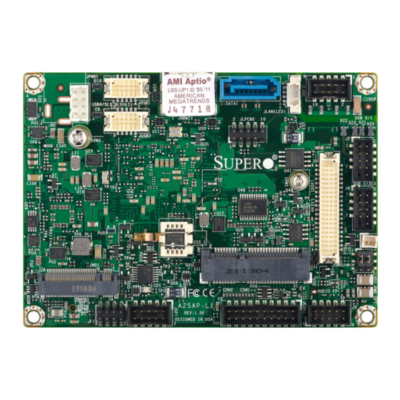
A secure data deletion tool designed to fully erase all data from storage devices can be found at our website: https://www.supermicro.com/about/policies/disclaimer.cfm?url=/wdl/ utility/Lot9_Secure_Data_Deletion_Utility/ • If you have any questions, please contact our support team at: support@supermicro.com This manual may be periodically updated without notice. Check the Supermicro website for possible updates to the manual revision level. - Page 8 Super A2SAP-L1 User's Manual Figure 1-1. A2SAP-L1Motherboard Images Front Image Back Image Note: All graphics shown in this manual were based upon the latest PCB revision available at the time of publication of the manual. The motherboard you received may...
- Page 9 Chapter 1: Introduction Figure 1-2. Motherboard Mechanical Drawings Top Side Bottom Side...
- Page 10 Super A2SAP-L1 User's Manual Figure 1-3. Motherboard Back Panel I/O Mechanical Drawings Back Panel I/O without Heatsink Back Panel I/O with Heatsink...
- Page 11 Chapter 1: Introduction Figure 1-4. Motherboard Layouts (not drawn to scale) Top Layout JPWR1 JUSB1 JLAN1 JLAN1LED1 JHDMI1 USB 0/1 JUSB2 SRW2 JLPC SRW1 JMP1 JMD1 JLCDPWR1 LED1 JCOM1: COM1/COM2 J3: AUDIO FP A2SAP-L1 REV:1.00 DESIGNED IN USA Bottom Layout CPU1 JSMBUS1...
-
Page 12: Quick Reference
Super A2SAP-L1 User's Manual Quick Reference Top Layout JUSB2 JLAN1 I-SATA1 JPWR1 JHDMI1 JLAN1LED1 JUSB1 JPWR1 JUSB1 JLAN1 JLAN1LED1 JHDMI1 USB 0/1 SRW2 JUSB2 SRW2 JLPC USB0/1 SRW1 USB2/3 LVDS1 JMP1 JLCDPWR1 JMD1 JLCDPWR1 JMD1 LED1 JCOM1: COM1/COM2 J3: AUDIO FP A2SAP-L1 REV:1.00... -
Page 13: Quick Reference Table
Chapter 1: Introduction Quick Reference Table Jumper Description Jumper Setting (Default *) Pins 2-4* (FORCE POWER ON) FORCE POWER ON Pins 4-6 (POWER BUTTON ON) JLCDPWR1 Pins 1-3* (3.3V) LVDS Panel Power Source Selection Pins 3-5 (5V) Description Status Solid Green: S0 mode LED1 Power LED Solid Red: S3/S4/S5 modes... -
Page 14: Motherboard Features
Super A2SAP-L1 User's Manual Motherboard Features Motherboard Features • A2SAP-L1: Intel® Atom SoC E3940 Processor, Quad Core, 2 MB L2 Cache, 1.6GHz-1.8GHz, 9.5W Memory • Integrated memory controller supports up to 8GB of DDR3L 1867MHz Non-ECC 204-pin SO-DIMM DIMM Size •... - Page 15 Chapter 1: Introduction Motherboard Features Power Management • ACPI power management • S3, S4, S5 • Power button override mechanism • Power-on mode for AC power recovery • Wake-On-LAN • TXE Management Engine • Force Power On by Jumper • RTC Battery (typical voltage: 3.0V, normal discharge capacity: 220mAh) System Health Monitoring •...
- Page 16 Super A2SAP-L1 User's Manual Figure 1-6. System Block Diagram MAX. 8G SO-DIMM SUPPORTED SINGLE CHANNEL Non-ECC-SODIMM0 DDR3L DDI0 Intel HDMI connector 1866/1600/1333 MHz DDR3L non ECC SKU High Definition REALTEK Audio FRONT AUDIO Header PTN3460 LVDS Connector ALC888S-VD2-GR DP to LVDSBridge...
-
Page 17: Processor Overview
Chapter 1: Introduction 1.2 Processor Overview Built upon the functionality and capability of the Intel Atom SoC processor, the A2SAP-L1 motherboard offers maximum I/O expandability, energy efficiency, and data reliability in a 14-nm process architecture, and is optimized for embedded storage solutions, networking applications, or cloud-computing platforms. -
Page 18: Acpi Features
Super A2SAP-L1 User's Manual 1.4 ACPI Features The Advanced Configuration and Power Interface (ACPI) specification defines a flexible and abstract hardware interface that provides a standard way to integrate power management features throughout a computer system including its hardware, operating system and application software. -
Page 19: Advanced Power Management
Chapter 1: Introduction 1.7 Advanced Power Management The following new advanced power management features are supported by the motherboard. Management Engine (ME) Intel Atom SoC only supports the TXE function, also called Converged Security Engine(CSE), which is the lite ME function. -
Page 20: Chapter 2 Installation
Super A2SAP-L1 User's Manual Chapter 2 Installation 2.1 Static-Sensitive Devices Electrostatic Discharge (ESD) can damage electronic com ponents. To prevent damage to your motherboard, it is important to handle it very carefully. The following measures are generally sufficient to protect your equipment from ESD. -
Page 21: Motherboard Installation
JMD1 JLCDPWR1 LED1 JCOM1: COM1/COM2 J3: AUDIO FP A2SAP-L1 REV:1.00 DESIGNED IN USA Location of Mounting Holes Note: 1) To avoid damaging the motherboard and its components, please do not use a force greater than 8 lb/inch on each mounting screw during motherboard installation. -
Page 22: Installing The Motherboard
Super A2SAP-L1 User's Manual Installing the Motherboard 1. Locate the mounting holes on the motherboard. See the previous page for the location. 2. Install standoffs in the chassis. 3. Install the memory. Follow section 2.3 - Memory Support and Installation 4. -
Page 23: Memory Support And Installation
Important: Exercise extreme care when installing or removing DIMM modules to pre- vent any possible damage. Memory Support The A2SAP-L1 supports up to 8GB of DDR3L Non-ECC SO-DIMM with speeds of 1333/1600/1867MHz in one memory slot on the bottom side of the motherboard. Bottom Layout... -
Page 24: So-Dimm Installation
Super A2SAP-L1 User's Manual SO-DIMM Installation 1. Position the SO-DIMM module's bottom key so it aligns with the receptive point on the slot. Align 2. Insert the SO-DIMM module vertically at about a 45 degree angle. Press down until the module locks into place. -
Page 25: Rear I/O Ports
JHDMI1 USB 0/1 JUSB2 SRW2 JLPC SRW1 JMP1 JMD1 JLCDPWR1 LED1 JCOM1: COM1/COM2 J3: AUDIO FP A2SAP-L1 REV:1.00 DESIGNED IN USA Figure 2-1. Rear I/O Port Locations and Definitions Rear I/O Ports Description Description LAN1 USB1 LAN1LED1 USB2 I-SATA1 PWR1... - Page 26 Super A2SAP-L1 User's Manual LAN Port One communication port (JLAN1) is located on the I/O back panel. The port supports RJ45 type cables. The LAN port has one two LEDs (located at JLAN1LED1) right next to it. Please refer to the LED Indicator section for LAN LED information. Refer to the table below for pin defintions.
- Page 27 USBCON_N1 USBCON_P2 USBCON_P3 USBCON_P0 USBCON_P1 Key Pin JPWR1 JUSB1 JLAN1 1. JUSB1 JLAN1LED1 JHDMI1 2. JUSB2 USB 0/1 JUSB2 SRW2 JLPC 3. USB0/1 4. USB2/3 SRW1 JMP1 JMD1 JLCDPWR1 LED1 JCOM1: COM1/COM2 J3: AUDIO FP A2SAP-L1 REV:1.00 DESIGNED IN USA...
-
Page 28: Front Control Panel
Super A2SAP-L1 User's Manual 2.5 Front Control Panel JF1 contains header pins for various buttons and indicators that are normally located on a control panel at the front of the chassis. These connectors are designed specifically for use with a custom chassis. Refer to the figure below for the descriptions of the front control panel buttons and LED indicators. - Page 29 Chapter 2: Installation Power Button The Power Button connection is located on pins 1 and 2 of JF1. Momentarily contacting both pins will power on/off the system. This button can also be configured to function as a suspend button (with a setting in the BIOS - see Chapter 4). To turn off the power in the suspend mode, press the button for at least 4 seconds.
- Page 30 Super A2SAP-L1 User's Manual HDD LED The HDD LED connection is located on pins 5 and 6 of JF1. Attach a cable here to indicate the status of HDD-related activities, including SATA activities. Refer to the table below for pin definitions.
-
Page 31: Connectors
12V DC Power Pin Definition Pin# Definition P12VSB 1. 12V DC Power JPWR1 (JPWR1: 2x4 pin box JUSB1 JLAN1 header) JLAN1LED1 JHDMI1 USB 0/1 JUSB2 SRW2 JLPC SRW1 JMP1 JMD1 JLCDPWR1 LED1 JCOM1: COM1/COM2 J3: AUDIO FP A2SAP-L1 REV:1.00 DESIGNED IN USA... -
Page 32: Headers And Connectors
Super A2SAP-L1 User's Manual Headers and Connectors Front Panel Audio Header A 10-pin front panel audio header located on the motherboard allows you to use the onboard sound for audio playback. Connect an audio cable to the this header to use this feature. Refer to the table below for pin definitions. - Page 33 RS-485_COM2_Data+ (Half Duplex) TXD or RS-485/422_COM2_RX+ (Full Duplex) DTR or RS-485/422_COM2_RX- (Full Duplex) RI_N SATA Ports The A2SAP-L1 has one SATA 3.0 port (I-SATA1) that is supported by the Intel Atom SoC. JPWR1 1. JCOM1 JUSB1 JLAN1 2. I-SATA1...
- Page 34 Super A2SAP-L1 User's Manual LVDS Connector LVDS1 is the LVDS connector. Low-voltage Differential Signaling (LVDS) is a high-speed digital interface that operates at low power. It is a type of connection that is used with a LVDS LCD panel. The connector combines LCD VCC Power (pins 9-10), LVDS high speed digital interface, backlight power 3.3V (pin 7) and 12V (pins 1-5), backlight enable (pin 15),...
- Page 35 Pin# Definition P3V3SB GP_P3V3_GP0 GP_P3V3_GP4 GP_P3V3_GP1 GP_P3V3_GP5 GP_P3V3_GP2 GP_P3V3_GP6 GP_P3V3_GP3 GP_P3V3_GP7 1. General Purpose JPWR1 Header JUSB1 JLAN1 JLAN1LED1 JHDMI1 USB 0/1 JUSB2 SRW2 JLPC SRW1 JMP1 JMD1 JLCDPWR1 LED1 JCOM1: COM1/COM2 J3: AUDIO FP A2SAP-L1 REV:1.00 DESIGNED IN USA...
- Page 36 M.2 is formerly known as Next Generation P3V3SB Form Factor (NGFF) and is located at JMD1 P3V3SB on the motherboard. The M.2 slot is designed FULL_CARD_POW- for internal mounting devices. The A2SAP-L1 ER_OFF#(PU to P1V8SB only) motherboard deploys a B-KEY for SATA/PCIe USB_D+ W_DISABLE1#(PU...
- Page 37 1. Mini PCIe PERp0 +3.3Vaux PERn0 JPWR1 PERST# DET_CARD_ PLUG JUSB1 JLAN1 JLAN1LED1 JHDMI1 USB 0/1 JUSB2 SRW2 JLPC REFCLK+ SRW1 REFCLK- JMP1 CLKREQ# JMD1 1.5V JLCDPWR1 LED1 JCOM1: COM1/COM2 J3: AUDIO FP A2SAP-L1 REV:1.00 3.3Vaux WAKE# DESIGNED IN USA...
- Page 38 Super A2SAP-L1 User's Manual System Management Bus Header and SATA Power A System Management Bus header for additional slave devices or sensors is located at JSMBUS1 on the bottom side of the motherboard. This header also serves as a 5V/1A SATA power box header.
-
Page 39: Jumper Settings
Chapter 2: Installation 2.7 Jumper Settings How Jumpers Work To modify the operation of the motherboard, jumpers can be used to choose between optional settings. Jumpers create shorts between two pins to change the function of the connector. Pin 1 is identified with a square solder pad on the printed circuit board. See the diagram below for an example of jumping pins 1 and 2. - Page 40 Super A2SAP-L1 User's Manual JLCDPWR1 LVDS VCC Power Source Selection Use this jumper to select the power voltage for the LVDS panel. Make sure that the specifications of the cable is compatible with the panel to prevent damage. See the table below for jumper setting information.
-
Page 41: Led Indicators
Solid Green S0 mode Solid Red S3/S4/S5 modes 1. JLAN1 Port LED JPWR1 2. Power LED JUSB1 JLAN1 JLAN1LED1 JHDMI1 USB 0/1 JUSB2 SRW2 JLPC SRW1 JMP1 JMD1 JLCDPWR1 LED1 JCOM1: COM1/COM2 J3: AUDIO FP A2SAP-L1 REV:1.00 DESIGNED IN USA... -
Page 42: Chapter 3 Troubleshooting
Super A2SAP-L1 User's Manual Chapter 3 Troubleshooting 3.1 Troubleshooting Procedures Use the following procedures to troubleshoot your system. If you have followed all of the procedures below and still need assistance, refer to the ‘Technical Support Procedures’ and/ or ‘Returning Merchandise for Service’ section(s) in this chapter. Always disconnect the AC power cord before adding, changing or installing any non hot-swap hardware components. -
Page 43: Memory Errors
Chapter 3: Troubleshooting Memory Errors 1. Make sure that the DIMM modules are properly and fully installed. 2. Confirm that you are using the correct memory. Also, it is recommended that you use the same memory type and speed for all DIMMs in the system. See Section 2.4 for memory details. - Page 44 Super A2SAP-L1 User's Manual B. If the system becomes unstable before or during OS installation, check the following: 1. Source of installation: Make sure that the devices used for installation are working properly, including boot devices such as CD/DVD and CD/DVD-ROM.
-
Page 45: Technical Support Procedures
1. Please review the ‘Troubleshooting Procedures’ and 'Frequently Asked Questions' (FAQs) sections in this chapter or see the FAQs on our website at http://www. supermicro.com/FAQ/index.php before contacting Technical Support. 2. BIOS upgrades can be downloaded from our website at http://www.supermicro.com/ ResourceApps/BIOS_IPMI_Intel.html. -
Page 46: Frequently Asked Questions
3.3 Frequently Asked Questions Question: What type of memory does my motherboard support? Answer: The A2SAP-L1 motherboard supports up to 8GB of DDR3L 1867MHz Non-ECC SO-DIMM. See Section 2.3 for details on installing memory. Question: How do I update my BIOS? Answer: It is recommended that you do not upgrade your BIOS if you are not experiencing any problems with your system. -
Page 47: Battery Removal And Installation
Chapter 3: Troubleshooting 3.4 Battery Removal and Installation Battery Removal To remove the battery, follow the steps below: 1. Power off your system and unplug your power cable. 2. Remove the battery cable at the BT1 connector on the board. 3. -
Page 48: Returning Merchandise For Service
Super A2SAP-L1 User's Manual 3.5 Returning Merchandise for Service A receipt or copy of your invoice marked with the date of purchase is required before any warranty service will be rendered. You can obtain service by calling your vendor for a Returned Merchandise Authorization (RMA) number. -
Page 49: Chapter 4 Bios
BIOS 4.1 Introduction This chapter describes the AMIBIOS™ Setup utility for the A2SAP-L1 motherboard. The BIOS is stored on a chip and can be easily upgraded using a flash program. Note: Due to periodic changes to the BIOS, some settings may have been added or deleted and might not yet be recorded in this manual. -
Page 50: Main Setup
Super A2SAP-L1 User's Manual 4.2 Main Setup When entering the AMI BIOS setup utility, you start the Main setup screen. You can always return to the Main setup screen by selecting the Main tab on the top of the screen. The Main BIOS setup screen is shown below. - Page 51 Chapter 4: BIOS MRC Version This displays the MRC version of the BIOS ROM used in the system. TXT FW This displays the TXT FW of the BIOS ROM used in the system. This displays the GOP of the BIOS ROM used in the system.
-
Page 52: Advanced
Super A2SAP-L1 User's Manual 4.3 Advanced Use the arrow keys to select Advanced setup and press <Enter> to access the submenu items: Warning: Take caution when changing the Advanced settings. An incorrect value, a very high DRAM frequency or an incorrect BIOS timing setting may cause the system to malfunction. - Page 53 Chapter 4: BIOS Wait For "F1" If Error This feature forces the system to wait until the F1 key is pressed if an error occurs. The options are Disabled and Enabled. INT19 Trap Response Interrupt 19 is the software interrupt that handles the boot disk function. When this feature is set to Immediate, the ROM BIOS of the host adapters will "capture"...
- Page 54 Super A2SAP-L1 User's Manual • Min CPU Speed • Processor Cores • Intel HT Technology • Intel VT-X Technology • L1 Data Cache • L1 Code Cache • L2 Cache • L3 Cache • Speed • 64-bit CPU Power Management...
- Page 55 Chapter 4: BIOS Power Limit 1 Clamp Mode Use this feature to enable or disable Power Limit 1 Clamp Mode. The options are Dis- abled and Enabled. Power Limit 1 Power Use this feature to select Power Limit 1 power (in watts). Auto will program Power Limit 1 based on silicon default support value.
- Page 56 Super A2SAP-L1 User's Manual Chipset Configuration Warning: Setting the wrong values in the following sections may cause the system to malfunc- tion. North Bridge Graphics Configuration GOP driver Enable GOP Diver will unload VBIOS; disable it will load VBIOS. The options are Dis- able and Enable.
- Page 57 Chapter 4: BIOS DVMT Total Gfx Mem Use this feature to set the total memory size to be used by internal graphics devices based on the DVMT 5.0 platform. The options are 128MB, 256MB, and MAX. GT PM Support Use this feature to enable the IGFX Power Management function. The options are En- able and Disable.
- Page 58 Super A2SAP-L1 User's Manual M.2 Slot B-key ASPM Use this feature to set the Active State Power Management (ASPM) level for a PCI-E device. Select Auto for the system BIOS to automatically set the ASPM level based on the system configuration. Select Disabled to disable ASPM support. The options are Disable, L0s, L1, L0sL1, and Auto.
- Page 59 Chapter 4: BIOS USB Configuration USB3.0 Support This feature enables support for USB 2.0 and older. The options are Enable and Disable. XHCI Pre-Boot Driver Use this feature to enable or disable XHCI Pre-Boot Driver support. The options are Disable and Enable.
- Page 60 Super A2SAP-L1 User's Manual SATA Device Type Use this feature to specify if the specified SATA port should be connected to a Solid State Drive or a Hard Disk Drive. The options are Hard Disk Drive and Solid State Drive.
- Page 61 Chapter 4: BIOS Super IO Configuration Super IO Configuration Super IO Chip: NCT5523D Serial Port 1 Configuration Serial Port 1 Select Enabled to enable the onboard serial port specified by the user. The options are Disabled and Enabled. Device Settings This feature displays the base I/O port address and the Interrupt Request address of a serial port specified by the user.
- Page 62 Super A2SAP-L1 User's Manual Change Settings This feature specifies the base I/O port address and the Interrupt Request address of Serial Port 2. Select Auto to allow the BIOS to automatically assign the base I/O and IRQ address to a serial port specified. The options are Auto, (IO=2F8h; IRQ=3), (IO=3F8h; IRQ=3, 4, 5, 6, 7, 9, 10, 11, 12), (IO=2F8h;...
- Page 63 Chapter 4: BIOS Serial Port Console Redirection COM1 COM1 Console Redirection Select Enabled to enable console redirection support for a serial port specified by the user. The options are Enabled and Disabled. *If the feature above is enabled, the following features are available for configuration: Com1 Console Redirection Settings This feature allows you to specify how the host computer exchanges data with the client computer, which is the remote computer used by the user.
- Page 64 Super A2SAP-L1 User's Manual Com1 Flow Control Use this feature to set the flow control for Console Redirection to prevent data loss caused by buffer overflow. Send a "Stop" signal to stop sending data when the receiving buffer is full. Send a "Start" signal to start sending data when the receiving buffer is empty. The options are None and Hardware RTS/CTS.
- Page 65 Chapter 4: BIOS Com2 Terminal Type Use this feature to select the target terminal emulation type for Console Redirection. Select VT100 to use the ASCII Character set. Select VT100+ to add color and function key support. Select ANSI to use the Extended ASCII Character Set. Select VT-UTF8 to use UTF8 encoding to map Unicode characters into one or more bytes.
- Page 66 Super A2SAP-L1 User's Manual Com2 Resolution 100x31 Select Enabled for extended-terminal resolution support. The options are Disabled and Enabled. Com2 Legacy OS Redirection Resolution Use this feature to select the number of rows and columns used in Console Redirection for legacy OS support. The options are 80x24 and 80x25.
- Page 67 Chapter 4: BIOS UTF8 encoding to map Unicode characters into one or more bytes. The options are VT100, VT100+, VT-UTF8, and ANSI. Bits Per Second This feature sets the transmission speed for a serial port used in Console Redirection. Make sure that the same speed is used in the host computer and the client computer. A lower transmission speed may be required for long and busy lines.
- Page 68 Super A2SAP-L1 User's Manual PCIe/PCI/PnP Configuration The following PCI information will be displayed: • PCI Bus Driver Version • PCI Devices Common Settings Above 4G Decoding (Available if the system supports 64-bit PCI decoding) Select Enabled to decode a PCI device that supports 64-bit in the space above 4G Address.
- Page 69 Chapter 4: BIOS Media detect count Use this option to specify the number of times media is checked. Press "+" or "-" on your keyboard to change the value. The default setting is 1. iSCSI Configuration iSCSI Initiator Name This option allows you to enter the unique name of the iSCSI Initiator in IQN format.
- Page 70 Super A2SAP-L1 User's Manual Device Name This feature displays the adapter device name. Chip Type This feature displays the network adapter chipset name. PCI Device ID This feature displays the device ID number. PCI Address This feature displays the PCI address for this computer. PCI addresses are 3 two-digit hexadecimal numbers.
-
Page 71: Security
Chapter 4: BIOS 4.4 Security Use this menu to configure Security settings. Password Check Use this feature to determine when a password entry is required. Select Setup to require the password only when entering setup. Select Always to require the password when entering setup and at each bootup. - Page 72 Super A2SAP-L1 User's Manual Secure Boot Mode This feature allows you to select the desired secure boot mode for the system. The options are Standard and Custom. CSM Support This feature is for manufacturing debugging purposes. The options are Disabled and Enabled.
- Page 73 Chapter 4: BIOS Set New Var Use this option to set new variables to configure the setting for key exchange keys. Append Key Use this option to load the KEK from factory default or No to load from a file or external media.
- Page 74 Super A2SAP-L1 User's Manual Authorized TimeStamps Use this feature to configure the setting for dbt keys. The options are Set New Var and Append Key. Save to File Use this option to save the dbt keys to the key database.
-
Page 75: Boot
Chapter 4: BIOS 4.5 Boot Use this menu to configure Boot settings: Boot Mode Select Use this feature to select the type of device that the system is going to boot from. The options are Legacy, UEFI, and Dual. FIXED BOOT ORDER Priorities This feature prioritizes the order of bootable devices that the system can boot from. - Page 76 Super A2SAP-L1 User's Manual UEFI Application Boot Priorities This feature allows you to specify which UEFI application devices are boot devices. • Boot Option #1 UEFI NETWORK Drive BBS Priorities This feature allows you to specify which network drives are boot devices.
-
Page 77: Save & Exit
Chapter 4: BIOS 4.6 Save & Exit Select the Exit tab from the BIOS setup utility screen to enter the Exit BIOS Setup screen. Save Options Discard Changes and Exit Select this feature to exit the BIOS without saving any changes. Save Changes and Reset When you have completed the system configuration changes, select this option to save all changes made and reset the system. - Page 78 Super A2SAP-L1 User's Manual Default Options Restore Defaults To set this feature, select Restore Defaults from the Exit menu and press <Enter>. These are factory settings designed for maximum system performance but not for maximum stability. Save as User Defaults To set this feature, select Save as User Defaults from the Exit menu and press <Enter>.
-
Page 79: Appendix A Software
USB/SATA DVD drive, or a USB flash drive, or the IPMI KVM console. 2. Retrieve the proper RST/RSTe driver. Go to the Supermicro web page for your motherboard and click on "Download the Latest Drivers and Utilities", select the proper driver, and copy it to a USB flash drive. - Page 80 Super A2SAP-L1 User's Manual 4. During Windows Setup, continue to the dialog where you select the drives on which to install Windows. If the disk you want to use is not listed, click on “Load driver” link at the bottom left corner.
-
Page 81: Driver Installation
ISO file if preferred. Another option is to go to the Supermicro website and search for the motherboard. Find the product page for your motherboard and download the latest drivers and utilities. -
Page 82: Superdoctor ® 5
A.3 SuperDoctor ® The Supermicro SuperDoctor 5 is a program that functions in a command-line or web-based interface for Windows and Linux operating systems. The program monitors such system health information as CPU temperature, system voltages, system power consumption, fan speed, and provides alerts via email or Simple Network Management Protocol (SNMP). -
Page 83: Ipmi
Appendix B: Software A.4 IPMI The A2SAP-L1 supports the Intelligent Platform Management Interface (IPMI). IPMI is used to provide remote access, monitoring and management. There are several BIOS settings that are related to IPMI. For general documentation and information on IPMI, please visit our website at: http://www. -
Page 84: Appendix B Standardized Warning Statements
The following statements are industry standard warnings, provided to warn the user of situations which have the potential for bodily injury. Should you have questions or experience difficulty, contact Supermicro's Technical Support department for assistance. Only certified technicians should attempt to install or configure components. - Page 85 Appendix B: Warning Statements Attention Danger d'explosion si la pile n'est pas remplacée correctement. Ne la remplacer que par une pile de type semblable ou équivalent, recommandée par le fabricant. Jeter les piles usagées conformément aux instructions du fabricant. ¡Advertencia! Existe peligro de explosión si la batería se reemplaza de manera incorrecta.
-
Page 86: Product Disposal
Super A2SAP-L1 User's Manual Product Disposal Warning! Ultimate disposal of this product should be handled according to all national laws and regulations. 製品の廃棄 この製品を廃棄処分する場合、 国の関係する全ての法律 ・ 条例に従い処理する必要があります。 警告 本产品的废弃处理应根据所有国家的法律和规章进行。 警告 本產品的廢棄處理應根據所有國家的法律和規章進行。 Warnung Die Entsorgung dieses Produkts sollte gemäß allen Bestimmungen und Gesetzen des Landes erfolgen. -
Page 87: Appendix C Uefi Bios Recovery
Warning: Do not upgrade the BIOS unless your system has a BIOS-related issue. Flashing the wrong BIOS can cause irreparable damage to the system. In no event shall Supermicro be liable for direct, indirect, special, incidental, or consequential damages arising from a BIOS update. - Page 88 Super A2SAP-L1 User's Manual The file system supported by the recovery block is FAT (including FAT12, FAT16, and FAT32), which is installed on a bootable or non-bootable USB-attached device. However, the BIOS might need several minutes to locate the SUPER.ROM file if the media size becomes too large due to the huge volumes of folders and files stored in the device.
- Page 89 Appendix D: UEFI BIOS Recovery 2. Insert the USB device that contains the new BIOS image ("Super.ROM") into your USB port and reset the system until the following screen appears: 3. After locating the new BIOS binary image, the system will enter the BIOS Recovery menu as shown below: Note: At this point, you may decide if you want to start the BIOS recovery.
- Page 90 Super A2SAP-L1 User's Manual 4. When the screen as shown above displays, use the arrow keys to select the item "Proceed with flash update" and press the <Enter> key. You will see the BIOS recovery progress as shown in the screen below: Note: Do not interrupt the BIOS flashing process until it has completed.
- Page 91 Appendix D: UEFI BIOS Recovery 8. When the UEFI Shell prompt appears, type fs# to change the device directory path. Go to the directory that contains the BIOS package you extracted earlier from Step 6. Enter flash.nsh BIOSname.### at the prompt to start the BIOS update process. Note: Do not interrupt this process until the BIOS flashing is complete.
Need help?
Do you have a question about the A2SAP-L1 and is the answer not in the manual?
Questions and answers