
Related Manuals for Supermicro AOC-SIMLP-B


Summary of Contents for Supermicro AOC-SIMLP-B
- Page 1 AOC-SIMLP-B AOC-SIMLP-B+ AOC-SIMLP-3 AOC-SIMLP-3+ Add-on Cards User’s Manual Revison 1.0d...
- Page 2 Please Note: For the most up-to-date version of this manual, please see our web site at www.supermicro.com. Super Micro Computer, Inc. (“Supermicro”) reserves the right to make changes to the product described in this manual at any time and without notice. This product, including software, if any, and documentation may not, in whole or in part, be copied, photocopied, reproduced, translated or reduced to any medium or machine without prior written consent.
-
Page 3: About This Manual
About this Manual This user's guide is written for system integrators, PC technicians and knowledgeable PC users who intend to integrate Supermicro's unique IPMI 2.0 Management Utility with support of KVM-over-LAN into their systems. It provides detailed information for the... - Page 4 IPMI Version 2.0. The key features include the following: • Supports IPMI 2.0 over LAN • Supports serial over LAN • Supports KVM over LAN (AOC-SIMLP-B+ and AOC-SIMLP-3+ add-on cards only) • Supports Virtual Media over LAN • Supports LAN alerting-SNMP trap • Supports an Event Log •...
-
Page 5: Product Features
Please refer to the following checklist when contacting us. Included Items • AOC-SIMLP-B/AOC-SIMLP-B/AOC-SIMLP-B+/AOC-SIMLP-3/AOC-SIMLP-3+ • Brackets: One full-size bracket, one low-profile bracket and two screws • CDR-SIMIPMI: One Installation CD • A white box with the correct barcode label (showing AOC-SIMLP-B/ AOC-SIMLP-B+/AOC-SIMLP-3/AOC-SIMLP-3+). -
Page 6: An Important Note To Users
For faster service, RMA authorizations may be requested online at http://www.supermicro.com/support/rma/ Whenever possible, repack the add-on card in the original Supermicro box, using the original packaging materials. If these are no longer available, be sure to pack the add-on card in an anti-static bag and inside the box. Make sure that there is enough packaging material surrounding the add-on card so that it does not become damaged during shipping. -
Page 7: Contacting Supermicro
Super Micro Computer, Inc. 980 Rock Ave. San Jose, CA 95131 U.S.A. Tel: +1 (408) 503-8000 Fax: +1 (408) 503-8008 Email: marketing@supermicro.com (General Information) support@supermicro.com (Technical Support) Web Site: www.supermicro.com Europe Address: Super Micro Computer B.V. Het Sterrenbeeld 28, 5215 ML ‘s-Hertogenbosch, The Netherlands... - Page 8 Add-on Card User’s Manual Notes...
-
Page 9: Table Of Contents
Table of Contents Chapter 1 Safety Guidelines ............1-1 1-1 ESD Safety Guidelines ..............1-1 1-2 General Safety Guidelines ............... 1-1 Chapter 2 Technical Specifications and Hardware Installation ..............2-1 2-1 Components ..................2-1 2-2 Block Diagram ................... 2-2 Chapter 3 Software Application and Usage ...... - Page 10 Add-on Card User’s Manual Keyboard/Mouse ................3-28 Device Settings ..................3-29 Network ....................3-29 Dynamic DNS..................3-31 Security ....................3-33 Certificate ................... 3-36 Date/Time................... 3-38 Event Log ................... 3-40 Maintenance ..................3-42 Device Information ................3-42 Event Log ................... 3-43 Update Firmware................
-
Page 11: Chapter 1 Safety Guidelines
Chapter 1 Safety Guidelines WARNING: To avoid personal injury and property damage, please carefully follow all the safety steps listed below when installing the add-on card into your system. ESD Safety Guidelines Electric Static Discharge (ESD) can damage electronic components. To prevent damage to your system, it is important to handle it very carefully. - Page 12 Add-on Card User’s Manual Notes...
-
Page 13: Chapter 2 Technical Specifications And Hardware Installation
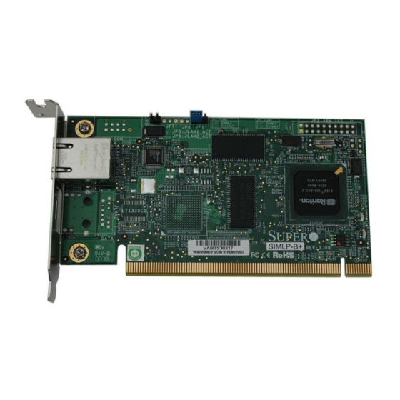
Chapter 2 Technical Specifications and Hardware Installation Components The front components of the AOC-SIMLP-B/AOC-SIMLP-B+/AOC-SIMLP-3/ AOC-SIMLP-3+ add-on card are shown in Figure 2-1. Rear components are shown in Figure 2-2. Figure 2-1. Add-on Card – Front View Figure 2-2. Add-on Card – Rear View Table 2-1 lists the add-on card’s components. -
Page 14: Block Diagram
D3: Power-on LED D4: Heartbeat (Activity) LED Flash DRAM (64 Mb/133 Mhz) (Rear) VRAM (64 Mb/166 Mhz) (Rear) Block Diagram Figure 2-3. Add-on Card Block Diagram The block diagram for the AOC-SIMLP-B/AOC-SIMLP-B+/AOC-SIMLP-3/ AOC-SIMLP-3+ add-on card is shown in Figure 2-3. -
Page 15: Chapter 3 Software Application And Usage
LAN. The necessary utilities for the access and configuration of the add-on card are included on the Supermicro bootable CDs that came with your card. This section provides information on the configuration and the access of the IPMI card on the network. -
Page 16: Accessing The Add-On Card
NOTE: The Readme.txt file is included in the CD that came with your shipment. A copy of the Readme.txt file, dated 07/11/2008, is also included below. IPMICFG Version 1.10 (Build 080711) Copyright 2008 SuperMicro Computer Inc. Usage: IPMICFG params (Example: IPMICFG -m 192.168.1.123) -
Page 17: Logging In
Chapter 3: Software Application and Usage Logging In Figure 3-1. Login Screen Once you are connected to the remote server, the L screen appears (Figure 3-1). OGIN To login, use the procedure below. Logging In to the IPMICFG Utility using the Login Screen: 1. -
Page 18: Home Page Screen
Add-on Card User’s Manual NOTE: KVM-over-LAN is available on the AOC-SIMLP-B+ and AOC-SIMLP-3+ add-on card only. Home Page Screen The H screen (Figure 3-2) appears after login. Table 3-1 lists and describes its components. Figure 3-2. Home Page Screen Table 3-1. Home Page Screen Components... -
Page 19: Home
Chapter 3: Software Application and Usage Table 3-1. Home Page Screen Components (Continued) Item Name Description Remote Console Displayed in the window is the R screen. Click on EMOTE ONSOLE Screen this window to go to the R screen. EMOTE ONSOLE Click on this icon to log out of the system. -
Page 20: Kvm Console
Add-on Card User’s Manual KVM Console Clicking on this menu option brings up the R screen (Figure 3-3) for EMOTE ONSOLE configuring settings for the remote host. See Table 3-3 for a list and description of major controls and features of this console screen. See also Section 3-6: "Remote Console Screen Controls"... -
Page 21: Sol Console
Chapter 3: Software Application and Usage SOL Console Click on this menu option to bring up the Serial over LAN (SOL) remote console. Figure 3-4. SOL Console Screen Table 3-4. SOL Console Screen Controls and Features Item Name Description Use this drop-down list box to set the Baud rate for the SOL Console Baud Rate to use. -
Page 22: Remote Power
Add-on Card User’s Manual Remote Power Click on this menu option to bring up the R screen (Figure 3-5) for EMOTE OWER configuring the power settings for the Remote Console. See Table 3-5 for a list and description of major controls in this screen. Figure 3-5. -
Page 23: Floppy Disk
The floppy image uploaded is in the binary format Floppy Image Upload with a maximum size of 1.44MB. It will be loaded to the Supermicro SIMBL card and will be emulated to the host as a USB device. -
Page 24: Cd-Rom Image
Add-on Card User’s Manual Table 3-6. Floppy Disk Screen Controls (Continued) Item Name Description Click on B to preview and select the files that you wish to ROWSE Floppy Image File upload to the host drive selected in Item 4 above. Once the correct file name appears in the box for the F LOPPY MAGE... - Page 25 Chapter 3: Software Application and Usage Table 3-7. CD-ROM Image Screen Controls Item Name Description This window displays the file name of the data currently active in host Active Image (Drive1) Drive 1. This window displays the file name of the data currently active in host Active Image (Drive2) Drive 2.
-
Page 26: Drive Redirection
Add-on Card User’s Manual Drive Redirection Click on this menu option to make local drives accessible for other users via console redirection, and brings up the D screen (Figure 3-8). See Table 3-8 RIVE EDIRECTION a list and description of controls in this screen. This function allows you to share your local drives (Floppy, CD-ROM and HDDs) with users in the remote systems. - Page 27 Chapter 3: Software Application and Usage Table 3-8. Driver Redirection Screen Controls (Continued) Item Name Description Check this box to allow the data stored in local drives to be read in a Force Read Only remote system, but it cannot be overwritten to ensure data integrity and system security.
-
Page 28: Virtual Media Options
Add-on Card User’s Manual Virtual Media Options Click on this menu option to bring up the V screen (Figure 3-9). IRTUAL EDIA PTIONS Table 3-9 for a list and description of controls in this screen. Figure 3-9. Virtual Media Options Screen Table 3-9. -
Page 29: System Health
Chapter 3: Software Application and Usage System Health Click on the S button to display the Chassis Control, Monitor Sensor, YSTEM EALTH System Event Log Alert Settings menu options. Chassis Control Click on this menu option to bring up the C screen (Figure 3-10). - Page 30 Add-on Card User’s Manual Table 3-10. Chassis Control Screen Controls Item Name Description The following remote chassis information are included: • Power Is: This indicates if the system is on or off for the remote host. • Power On Counter: If power is on, then the counter indicates the Chassis Information length of time the power has been turned on.
-
Page 31: Monitor Sensor
Chapter 3: Software Application and Usage Monitor Sensor Click on this menu option to bring up the M screen (Figure 3-11). This ONITOR ENSOR screen displays a table with health monitoring information. See Table 3-11 for details on this table’s information. Clicking the Refresh button refreshes the data in the screen. Figure 3-11. - Page 32 Add-on Card User’s Manual Table 3-11. Monitoring Sensors Table (Continued) Sensor Type Sensor Name Description CPU1 VCore CPU1 Vcore: CPU1 Core Voltage CPU2 VCore CPU2 Vcore: CPU2 Core Voltage 3.3V Voltage Monitoring 5V, 5VSB 5VSB: 5V Standby +12V, -12V 1.5V VBAT VBAT: Battery Voltage Fan1/CPU Fan...
-
Page 33: System Event Log
Chapter 3: Software Application and Usage System Event Log Click on this menu option to bring up the S screen (Figure 3-12). This YSTEM VENT screen displays the System Health Event Log for the remote host system. See Table 3-12 for details on this screen’s controls and features. -
Page 34: Alert Settings
Add-on Card User’s Manual Alert Settings Click on this menu option to bring up the A screen (Figure 3-13), which LERT ETTINGS displays alert settings for the remote host system. The items monitored include a F ILTER , a P and a LAN D . -
Page 35: User Management
Chapter 3: Software Application and Usage User Management Click on the U button to display the Change Password, Users & ANAGEMENT Groups Permissions menu options. Change Password Click on this menu option to bring up the C screen (Figure 3-14). See HANGE ASSWORD Table 3-13... -
Page 36: Users & Groups
Add-on Card User’s Manual Users & Groups Click on this menu option to bring up the U & G screen (Figure 3-15). See SERS ROUPS Table 3-14 for a list and description of controls in this screen. Figure 3-15. Users & Groups Screen Table 3-14. - Page 37 Chapter 3: Software Application and Usage Table 3-14. Users & Groups Screen Controls (Continued) Item Name Description This section allows you to enter Group Membership information. The field (Item 9) indicates the group that the user ROUP EMBERSHIP belongs to. To select a group: Click on the group name on the N pane EMBER...
-
Page 38: Permissions
Add-on Card User’s Manual Permissions Click on this menu option to bring up the P screen (Figure 3-16). See ERMISSIONS Table 3-15 for a list and description of controls in this screen. Figure 3-16. Permissions Screen Table 3-15. Permissions Screen Controls Item Name Description... -
Page 39: Kvm Settings
Chapter 3: Software Application and Usage KVM Settings Click on the KVM S button to display the User Console Keyboard/Mouse ETTINGS menu options. User Console Click on this menu option to bring up the U screen (Figure 3-17). See ONSOLE Table 3-16 for a list and description of controls in this screen. - Page 40 Add-on Card User’s Manual Table 3-16. User Console Screen Controls Item Name Description This drop-down list box allows you to select which group the user User Selection Field belongs to. Once you've selected the group name, click on the U button to PDATE Update Button...
- Page 41 Chapter 3: Software Application and Usage Table 3-16. User Console Screen Controls (Continued) Item Name Description Check this box to enable the Start in Monitor Mode, which allows data to be displayed in the remote monitor as soon as the Remote Start in Monitor Mode Console is activated.
-
Page 42: Keyboard/Mouse
Add-on Card User’s Manual Keyboard/Mouse Click on this menu option to bring up the K screen (Figure 3-18). See EYBOARD OUSE Table 3-17 for a list and description of controls in this screen. Figure 3-18. Keyboard/Mouse Screen Table 3-17. Keyboard/Mouse Screen Controls Item Name Description... -
Page 43: Device Settings
Chapter 3: Software Application and Usage Table 3-17. Keyboard/Mouse Screen Controls (Continued) Item Name Description Click on this button to apply your selections from this screen to the Apply Button system. Reset to Defaults You can cancel your selections and switch back to the default values Button by clicking on this button. - Page 44 Add-on Card User’s Manual Table 3-18. Network Screen Controls Item Name Description Network Basic This section allows you to configure basic settings for your network. Settings Select a desired item from this drop-down list for your IP Auto IP Auto Configuration Configuration.
-
Page 45: Dynamic Dns
Chapter 3: Software Application and Usage Table 3-18. Network Screen Controls (Continued) Item Name Description Click on this button to apply your selections from this screen to the Apply Button system. Reset to Defaults You can cancel your selections and switch back to the default values Button by clicking on this button. - Page 46 Add-on Card User’s Manual Table 3-19. Dynamic DNS Screen Controls (Continued) Item Name Description If you have enabled the Dynamic DNS (Item 1 above), then you can use this drop-down list box to select from the C or D USTOM YNAMIC DNS System options.
-
Page 47: Security
Chapter 3: Software Application and Usage Security Click on this menu option to bring up the S screen (Figure 3-21). See Table 3-20 ECURITY for a list and description of controls in this screen. Figure 3-21. Security Screen Table 3-20. Security Screen Controls Item Name Description... - Page 48 Add-on Card User’s Manual Table 3-20. Security Screen Controls (Continued) Item Name Description These options allow you to configure the encryption of the RFB protocol. RFB is used by the remote host to transmit video data displayed in the host monitor to the local administrator machine, and transmits keyboard and mouse data from the local administrator machine back to the remote host.
- Page 49 Chapter 3: Software Application and Usage Table 3-20. Security Screen Controls (Continued) Item Name Description Enter the maximum number of failed attempts or failed logins allowed for a user. If the number of failed logins or attempts exceeds this Max. Number of maximum number allowed, the user will be blocked from system.
-
Page 50: Certificate
Add-on Card User’s Manual Certificate Click on this menu option to bring up the C screen (Figure 3-22). See ERTIFICATE Table 3-21 for a list and description of controls in this screen. Figure 3-22. Certificate Screen Table 3-21. Certificate Screen Controls Item Name Description... - Page 51 Chapter 3: Software Application and Usage Table 3-21. Certificate Screen Controls (Continued) Item Name Description Enter the name of the city or the location where the organization is Locality/City located. Enter the name of the state/province where the organization is State/Province located.
-
Page 52: Date/Time
Add-on Card User’s Manual Date/Time Click on this menu option to bring up the D screen (Figure 3-23). See Table 3-22 for a list and description of controls in this screen. This screen allows you to set the internal real-time clock for your SIMBL card. Figure 3-23. - Page 53 Chapter 3: Software Application and Usage Table 3-22. Date/Time Screen Controls (Continued) Item Name Description Enter the IP Address for the primary NTP Server and the secondary NTP Server that you want your SIMBL internal real-time clock to Primary Time Server/ synchronize with.
-
Page 54: Event Log
Add-on Card User’s Manual Event Log Click on this menu option to bring up the E screen (Figure 3-24). See VENT Table 3-23 for a list and description of controls in this screen. Figure 3-24. Event Log Screen 3-40... - Page 55 Chapter 3: Software Application and Usage Table 3-23. Event Log Screen Controls Item Name Description This section allows you to manually set event log targets and Event Log Targets settings. Checking this box activates the event-logging list. To show the event log list, click on the E menu option from the M VENT...
-
Page 56: Maintenance
Add-on Card User’s Manual Maintenance Click on the M button to display the Device Information, Event Log, Update AINTENANCE Firmware Unit Reset menu options. Device Information Click on this menu option to bring up the D screen (Figure 3-25). See EVICE NFORMATION Table 3-24... -
Page 57: Event Log
Chapter 3: Software Application and Usage Event Log Click on this menu option to bring up the E screen (Figure 3-26). This brings VENT up the E list, which contains the information of events that are recorded by the VENT SIMBL in the order of Date/Time, Types, and the descriptions of the events including the IP address(es), person(s) and activities involved. -
Page 58: Update Firmware
Add-on Card User’s Manual Update Firmware Click on this menu option to bring up the U screen (Figure 3-27). See PDATE IRMWARE Table 3-25 for a list and description of controls in this screen. Figure 3-27. Update Firmware Screen Table 3-25. Update Firmware Screen Controls Item Name Description... -
Page 59: Unit Reset
Chapter 3: Software Application and Usage Unit Reset Click on this menu option to bring up the U screen (Figure 3-28). See ESET Table 3-26 for a list and description of controls in this screen. Figure 3-28. Unit Reset Screen Table 3-26. -
Page 60: Remote Console Screen Controls
Add-on Card User’s Manual Remote Console Screen Controls The R screen (Figure 3-29) contains additional controls and display EMOTE ONSOLE icons. These include a button for displaying D controls, an O RIVE EDIRECTION PTIONS menu and icons for displaying the status of the mouse and keyboard on the system. Figure 3-29. -
Page 61: Drive Redirection Controls
Chapter 3: Software Application and Usage Drive Redirection Controls The D controls (Figure 3-30) display is toggled on and off when the RIVE EDIRECTION button is clicked in the R RIVE EDIRECTION ONTROLS ISPLAY EMOTE ONSOLE screen. See Table 3-27 for a description of each of the controls shown in this display. -
Page 62: Options Menu
Add-on Card User’s Manual Options Menu After the remote console screen appears, click on the O button on the very upper PTION right corner to display the O menu for console video settings and options. PTIONS Table 3-28 contains a complete list and description of all the menu options in the menu. - Page 63 Chapter 3: Software Application and Usage Table 3-28. Remote Console Options Menu Options (Continued) Menu Option Description GPRS Sets the predefined video setting to GPRS download speeds. Sets the predefined video setting to GSM download speeds. Compression This sub-menu is used to set video compression. Video Optimized Select this option for the optimized video compression.
- Page 64 Add-on Card User’s Manual Figure 3-33. Chat Window 3-50...
-
Page 65: Chapter 4 Frequently Asked Questions
Chapter 4 Frequently Asked Questions Below for your reference are a couple of frequently asked questions and their answers. Question 1: How do I flash the firmware of an IPMI card such as a AOC-SIMLP-B/ AOC-SIMLP-B+/AOC-SIMLP-3/AOC-SIMLP-3+ add-on card? Answer: 1. Log on to the web interface page of the IPMI card by typing the IP address of the card. - Page 66 Add-on Card User’s Manual Notes...
- Page 67 Disclaimer The products sold by Supermicro are not intended for and will not be used in life support systems, medical equipment, nuclear facilities or systems, aircraft, aircraft devices, aircraft/emergency communication devices or other critical systems whose failure to perform be reasonably expected to result in significant injury or loss of life or catastrophic property damage.
- Page 68 Add-on Card User’s Manual Notes...
Need help?
Do you have a question about the AOC-SIMLP-B and is the answer not in the manual?
Questions and answers