
Related Manuals for Bender CC613-H Series


Summary of Contents for Bender CC613-H Series
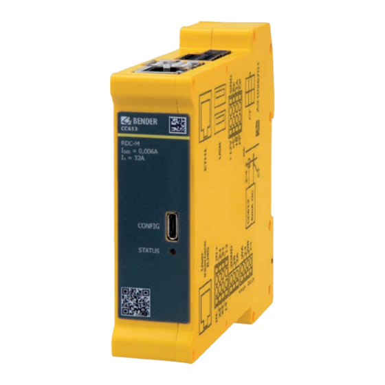
- Page 1 CC613-Hxx charge controller Charge controller for wallboxes CC613-Hxx_D00423_02_M_XXEN/11.2020 Manual EN...
- Page 2 Service and support for Bender products First-level support Technical support Carl-Benz-Strasse 8 • 35305 Grünberg • Germany Telephone: +49 6401 807-760 0700BenderHelp * Fax: +49 6401 807-629 E-mail: support@bender-service.de Available on 365 days from 7.00 a.m. to 8.00 p.m. (MEZ/UTC +1) * Landline German Telekom: Mon-Fri from 9.00 a.m.
-
Page 3: Table Of Contents
Signs and symbols ......................5 Training courses and seminars.................5 Delivery conditions .......................5 Inspection, transport and storage ................5 Warranty and liability....................6 Disposal of Bender devices ..................6 Safety ..........................6 Function ....................7 Intended use ........................7 Product features (depending on the variant) .............7 Product description ......................7 Functional description ....................7... - Page 4 Configuration and testing ............. 19 Configuration ....................... 19 5.1.1 Local configuration of parameters ..............19 5.1.2 Factory settings ......................20 5.1.3 Testing and system boot process ................ 20 5.1.3.1 Ethernet .............................21 5.1.4 Plug locking and unlocking (depending on the variant) ......21 5.1.5 Charging ........................
-
Page 5: General Instructions
Training courses and seminars www.bender.de > Know-how-> Seminars. Delivery conditions The conditions of sale and delivery set out by Bender apply. These can be obtained from Bender in printed or electronic format. The following applies to software products: "Softwareklausel zur Überlassung von Standard- Software als Teil von Lieferungen, Ergänzung und Änderung der Allgemeinen Lieferbedingungen für Erzeugnisse und Leistungen der... -
Page 6: Warranty And Liability
• Non-observance of technical data. • Repairs carried out incorrectly • Use of accessories and spare parts not recommended by Bender • Catastrophes caused by external influences and force majeure. • Mounting and installation with device combinations not recommended by the manufacturer. -
Page 7: Function
CC613-Hxx charge controller Function Local access to the charge controller Local access to the charge controller is possible either as operator or as manufacturer. Further details are described in chapter 5.1.1. Operator access is possible via the http://192.168.123.123/operator: - User name: operator - Password: yellow_zone The manufacturer can access the manufacturer area via the URL http://192.168.123.123/manufacturer: - User name: manufacturer... -
Page 8: General Functions (Depending On The Variant)
Function 2.4.1 General functions (depending on the variant) • The charging system can be equipped with a meter. A Modbus meter is required for digital reading of the energy consumption. The Modbus RTU wires are attached directly to the charge controller. •... -
Page 9: Dimensions And Mounting
CC613-Hxx charge controller Dimensions and mounting Dimensions 111 (112,3*) 23,5 Abb. 3–1 Note: Dimensions in mm acc. to ISO 2768 - m * Dimensions incl. antenna socket (depending on the variant) Mounting Click! DIN rail mounting Lateral distance to other equipment: 6 mm (self-heating) In horizontal mounting position the max. -
Page 10: Connection
Connection Connection Connection conditions of electric shock! Parts of the system may be live (charge controller terminals up to 230 V, charging station 400 V). Before touching parts of the system, ensure that it has been de-energised. ! Risk of injury from sharp-edged terminals! Handle enclosure and terminals with care. aution Information: •... - Page 11 CC613-Hxx charge controller CC613-Hxx_D00423_02_M_XXEN/11.2020...
-
Page 12: Charging System With Type 2 Socket-Outlet
Connection 4.2.2 Charging system with type 2 socket-outlet Wiring diagram front bottom 12 V Side view from right B Mod. A Mod. +12V – CC613-Hxx_D00423_02_M_XXEN/11.2020... - Page 13 CC613-Hxx charge controller Legend Connection measuring current transformer (CT) RCD type A 12 V supply, PE, Modbus meter, CP, PP Voltage supply DC 12 V 2x USB type A (depending on the variant) Measuring current transformer (CT) with plug Connection Ethernet (depending on the variant) Contactor Configuration interface Type 2 socket-outlet...
-
Page 14: Connection Locking Actuators (Depending On The Variant)
Connection 4.2.3 Connection locking actuators (depending on the variant) Type 2 socket-outlet (actuator type) Actua- Socket-outlet actuator wiring • Mennekes (31016, 31023, 31024, 31038) • Bals (801191-801195, 80300, 9743205000, Wire 3 Wire 1 Wire 2 9743211000) (///) (//) • Walther Werke (9743211000) Hella •... -
Page 15: Connectivity
CC613-Hxx charge controller Connectivity 4.3.1 USB configuration interface (CONFIG) The USB configuration interface (CONFIG) on the front panel of the charge controller is connected to a con- ventional laptop, PC or tablet computer via a micro USB cable. This interface allows local configuration of the charge controller. -
Page 16: Alternative Connection Switching Contact Contactor
Connection Wiring diagram of a short circuit! According to DIN VDE 0100-430, devices for protection against a short circuit can be omitted for the coupling of terminals WA and WB if the wiring is carried out in such a manner as to reduce the risk of a short circuit to a minimum. -
Page 17: Pe Monitoring
CC613-Hxx charge controller 4.3.8 PE monitoring The PE monitoring checks whether there is a connection from the CC613 to PE. For this purpose, L1 must be connected to WA. The cable length is limited by its capacitance per unit length. Pe monitoring does not replace tests (example: protective conductor resistance). - Page 18 Connection • inepro PRO1/PRO2/PRO380 • NZR EcoCount S85 • Optec • Phoenix Contact EEM-MB371 (TCP) • Saia ALE3 • Siemens 7KT1666/7KM2200 (TCP) Meter Slave ID Baud rate Parity Data Bit Stop Bit 9600 N (none) (except Saia) -> even Additional Modbus meters can be included in future software updates upon customer request. Refer to the Manufacturer tab on the web server for a list of supported Modbus meters.
-
Page 19: Configuration And Testing
CC613-Hxx charge controller Configuration and testing Configuration The following options are available for configuring the charging system: Access to web interface via the following interfaces: • Micro USB configuration interface (CONFIG) • Ethernet interface 5.1.1 Local configuration of parameters In order to locally configure the charging system via the charge controller, it is necessary to connect a micro USB cable to a laptop, PC or tablet computer with a standard USB host interface. -
Page 20: Factory Settings
Configuration and testing The Manufacturer tab of the charging system control interface can be accessed via the URL http://192.168.123.123/manufacturer. To access this tab, user name and password are required: • User name: manufacturer • Password: orange_zone The default passwords should be changed to prevent unauthorised access. The manufacturer can also change the user passwords and parameters via the Operator tab. -
Page 21: Ethernet
CC613-Hxx charge controller Fault messages are shown in the "Error list" on the State tab. The boot process starts once the charge controller is supplied with voltage (12 V). After about 30 s, the "STATUS" LED on the charge controller front panel lights up. After a short time, the "STATUS" LED flashes green in case of a successful boot process. -
Page 22: Technical Data
Technical data Technical data Tabular data Insulation coordination acc. to IEC 60664-1/IEC 60664-3 Rated voltage ....................................250 V Overvoltage category ............................. II (within terminal H) Overvoltage category ........................III (terminal H and all other terminals) Rated impulse voltage ......................6 kV (terminal H and all other terminals) Rated impulse voltage ............................. - Page 23 CC613-Hxx charge controller Inputs Weld check (terminal H (WB, WA)) Input voltage ................................AC 180 V…277 V Input current ..................................0.6…1.3 mA Input PE (terminal B (PE, PE)) Outputs Contact data acc. to IEC 60947-5-1: Switching contact for contactor (terminal H (relay 23, relay 24)) Rated operational voltage U ..............................
- Page 24 Technical data Connection specifications: rigid /flexible ............................0.2…1.5 mm² (AWG 24…16) flexible with ferrule without plastic sleeve .....................0.25…1.5 mm² (AWG 24…16) flexible with ferrule with plastic sleeve ....................0.25…0.75 mm² (AWG 24…18) Stripping length ..................................... 10 mm Max. connection cable length ................................2 m Cross-section ..................................
-
Page 25: Ordering Details
CC613-Hxx charge controller Ordering details Type Meter inter- Ethernet inter- USB host RDC-M PLC* Art� No� Manual face face Interface No� CC613-HB B94060024 D00423 Status CC613-HEM-X2 Modbus B94060028 D00423 * Powerline Communication acc. to ISO/IEC 15118 The charge controller with residual direct current monitoring module (RDC-M) only works in combination with the measuring current transformer (to be ordered separately). -
Page 26: Document Revision History
Technical data Document revision history Date Document Valid from soft- State/Changes version ware version 08/2020 10/2020 Added: Chapter 2: Local access charge controller Chapter 4.1: Ext. Modbus terminating resistor Chapter 4.2.2: Wiring diagram side view from right Chapter 4.2.2: Info on terminal I remote control Chapter 4.2.3: in table: Walther Werke Eco Slim 32 A Chapter 4.2.3: Connection Phoenix Contact (Küster) Chapter 4.3.14: Connection info terminal B... - Page 27 CC613-Hxx charge controller CC613-Hxx_D00423_02_M_XXEN/11.2020...
- Page 28 Nachdruck und Vervielfältigung Reprinting and duplicating nur mit Genehmigung des Herausgebers. only with permission of the publisher. Bender GmbH & Co. KG Bender GmbH & Co. KG Postfach 1161 • 35301 Grünberg • Deutschland PO Box 1161 • 35301 Grünberg • Germany Londorfer Str.
Need help?
Do you have a question about the CC613-H Series and is the answer not in the manual?
Questions and answers