Table of Contents
Advertisement
Quick Links
Advertisement
Table of Contents

Related Manuals for EXFO FOT-5200


Summary of Contents for EXFO FOT-5200
- Page 1 User Guide FOT-5200 CWDM Analyzer...
- Page 2 EXFO Inc. (EXFO). Information provided by EXFO is believed to be accurate and reliable. However, no responsibility is assumed by EXFO for its use nor for any infringements of patents or other rights of third parties that may result from its use.
-
Page 3: Table Of Contents
Main Functions ........................3 Conventions ..........................4 2 Safety Information ..................5 Battery Charger ........................6 3 Setting Up and Operating your FOT-5200 ........... 9 Cleaning and Connecting Optical Fibers .................9 Turning Unit On and Off .......................10 Menu Tree ..........................11 User Specification (CWDM SCAN) ..................16 Scanning All Channels (ALL SCAN) ..................18... - Page 4 Contents 6 Warranty ......................31 General Information ......................31 Liability ..........................32 Exclusions ..........................33 Certification ..........................33 Service and Repairs .......................34 EXFO Service Centers Worldwide ..................35 A Technical Specifications ................37 FOT-5200...
-
Page 5: Certification Information
Electronic test and measurement equipment is exempt from FCC part 15, subpart B compliance in the United States of America and from ICES-003 compliance in Canada. However, EXFO Inc. makes reasonable efforts to ensure compliance to the applicable standards. The limits set by these standards are designed to provide reasonable protection against harmful interference when the equipment is operated in a commercial environment. - Page 6 Tel.: +44 2380 246810 Equipment Type/Environment: Test & Measurement / Industrial Trade Name/Model No.: CWDM ANALYZER / FOT-5200 Standard(s) to which Conformity is declared: Safety requirements for electrical equipment for measurement, EN 61010-1:2001 Edition 2.0 control, and laboratory use – Part 1: General requirements Electrical equipment for measurement, control and laboratory use –...
-
Page 7: Introducing The Fot-5200 Cwdm Analyzer
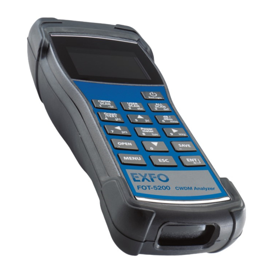
Thus for CWDM, which functions over several wavelengths, a device that can distinguish the wavelengths must be used. The FOT-5200 is developed to measure exact power and is adaptable to the various network conditions. It is especially suitable for outer environments and is compact, therefore easy to carry. - Page 8 Introducing the FOT-5200 CWDM Analyzer The picture below shows the FOT-5200, and the usage of the keypad essential in operating the measuring instrument. Optical port Display Power key User scan key CWDM scan key All scan key View mode key...
-
Page 9: Main Functions
Introducing the FOT-5200 CWDM Analyzer Main Functions The picture below shows the display screen when measuring a single channel. Current Optical module detection status measurement Date and time (shows X if not detected) mode Battery level Channel mode Current channel power... -
Page 10: Conventions
Introducing the FOT-5200 CWDM Analyzer Conventions Conventions Before using the product described in this guide, you should understand the following conventions: ARNING Indicates a potentially hazardous situation which, if not avoided, could result in death or serious injury. Do not proceed unless you understand and meet the required conditions. -
Page 11: Safety Information
Safety Information ARNING Do not install or terminate fibers while a light source is active. Never look directly into a live fiber and ensure that your eyes are protected at all times. ARNING Use of controls, adjustments and procedures for operation and maintenance other than those specified herein may result in hazardous radiation exposure or impair the protection provided by this unit. -
Page 12: Battery Charger
The LED on the charger module indicates different situations depending on its color and state: Color Status Red, ON (continuous) The charger module is in charging mode. Green, ON (continuous) Charge complete. Ready to use. Red, Blinking Error or damage to battery. FOT-5200... - Page 13 Safety Information Battery Charger Here are additional precautions pertaining to battery use: Charging time is about five hours. If the indicating lamp has changed add one more hour. Do not allow battery to short circuit. Keep the battery away from fire. There is danger of explosion when the ...
-
Page 15: Setting Up And Operating Your Fot-5200
To ensure maximum power and to avoid erroneous readings: Always inspect fiber ends and make sure that they are clean as explained below before inserting them into the port. EXFO is not responsible for damage or errors caused by bad fiber cleaning or handling. -
Page 16: Turning Unit On And Off
Setting Up and Operating your FOT-5200 Turning Unit On and Off 3. Carefully align the connector and port to prevent the fiber end from touching the outside of the port or rubbing against other surfaces. If your connector features a key, ensure that it is fully fitted into the port’s corresponding notch. -
Page 17: Menu Tree
Manages lighting of keypad FILE SYSTEM Functions for file management SET TIME To set time and date. SYSINFO Information on equipment CALIBRATION EXFO use only. Note: Malfunction of the FOT-5200 can occur due to incorrect setup of functions. CWDM Analyzer... - Page 18 Setting Up and Operating your FOT-5200 Menu Tree User-Defined Channels (USER SCAN) USER SCAN ( ) is a button assigned to scan only channels defined by the user. To set up USER SCAN: 1. Press MENU to change to the menu screen.
- Page 19 Setting Up and Operating your FOT-5200 Menu Tree When you press Graph/TEXT ( ) after performing a scan with the USER SCAN button, you can see a user scan graph screen such as the following. User Channel Graph Mode User Channel Text Mode...
- Page 20 Setting Up and Operating your FOT-5200 Menu Tree Communication Speed Set Up (USB, RS-232C, Baudrate) If you press the arrow keys in USB RS232C Baudrate, you can set up the transmission speed of the COM Port, and the default value is 115200 bps.
- Page 21 Setting Up and Operating your FOT-5200 Menu Tree File System Set Up (File System) This provides a function to delete the files saved in the FOT-5200 and format transportable memory. The following shows the screen when you select FILE SYSTEM in the menu, then press ENT.
-
Page 22: User Specification (Cwdm Scan)
User Specification (CWDM SCAN) Set Time (Set Time) This sets up the date and time on the FOT-5200, and is not deleted even after the power goes off. You change the value by pressing ENT after moving the selecting window using the arrow buttons. - Page 23 Setting Up and Operating your FOT-5200 User Specification (CWDM SCAN) To use the feature: 1. Press CWDM SCAN in display mode. 2. When you are asked for a channel selection, input the channel you want and press ENT. 3. Enter the channel you want using the number keys where the cursor blinks and press ENT.
-
Page 24: Scanning All Channels (All Scan)
Setting Up and Operating your FOT-5200 Scanning All Channels (ALL SCAN) Scanning All Channels (ALL SCAN) button scans all channels and shows a screen like the following. Scan all (Graph Mode) Scan all (Text Mode) If you press Graph/TEXT ( ) after scanning, a graph screen like the one on the right shows. -
Page 25: Finding Relative Value (Db) Of All Channels
Setting Up and Operating your FOT-5200 Finding Relative Value (dB) of All Channels Finding Relative Value (dB) of All Channels The following shows the relative value (dB) of all channels based on independent standard value (dBm), which appears when you press dB/dBm ( ) on the SCAN ALL screen. -
Page 26: General Power Meter
General Power Meter General Power Meter This shows the Power Meter in the basic set up screen without special manipulation when you turn on FOT-5200's power. Pressing Power meter ( ) changes the display mode into one-channel text view. One channel text view is good for observing one channel with a better visibility of the measurement. -
Page 27: Db/Dbm
1. Select the wavelength for measurement using CWDN SCAN button or the arrow buttons. 2. Connect the optical source connector which will be saved as the first reference value to the optic adaptor of FOT-5200. 3. To set up the first reference value (dBm) as relative value (dB), press dB/dBm and ensure it displays 0 dB. -
Page 28: Graph Data Display
Setting Up and Operating your FOT-5200 Graph Data Display Graph Data Display If you press the button, a bar graph is displayed for each channel value in an easy to read format. You can use this feature in CWDM SCAN, USER SCAN and SCAN ALL, and the following shows how it is displayed. -
Page 29: Saving Information And Naming Files
Setting Up and Operating your FOT-5200 Saving Information and Naming Files Saving Information and Naming Files Saving Files (Save) This saves the currently displayed value, and you can save all text and graph modes using the SAVE button ( In the display mode the reference values and the absolute power values of the 16 scanned channels are saved as a relative value (dB) and the file extension is .CSA. -
Page 30: Opening Files
Setting Up and Operating your FOT-5200 Opening Files key acts as a backspace button. If you want to exit without saving, press the ESC key until all of the file name letters have been deleted. Press once more on the ESC key. Press ENT when you are done. -
Page 31: Maintenance
Maintenance To help ensure long, trouble-free operation: Always inspect fiber-optic connectors before using them and clean them if necessary. Keep the unit free of dust. Clean the unit casing and front panel with a cloth slightly dampened with water. -
Page 32: Cleaning Detector Ports
3. While applying light pressure, gently rotate the cleaning tip on the detector window. 4. Repeat step 3 with a dry cleaning tip or blow dry with compressed air. 5. Discard the cleaning tips after one use. FOT-5200... -
Page 33: Recalibrating The Unit
You should determine the adequate calibration interval for your unit according to your accuracy requirements. Under normal use, EXFO recommends calibrating your unit every year. Recycling and Disposal (Applies to European Union Only) For complete recycling/disposal information as per European Directive WEEE 2002/96/EC, visit the EXFO Web site at www.exfo.com/recycle. -
Page 35: Troubleshooting
Contacting the Technical Support Group To obtain after-sales service or technical support for this product, contact EXFO at one of the following numbers. The Technical Support Group is available to take your calls from Monday to Friday, 8:00 a.m. to 7:00 p.m. -
Page 36: Viewing System Information
Pack the unit in its original packing material when shipping. Avoid high humidity or large temperature fluctuations. Keep the unit out of direct sunlight. Avoid unnecessary shocks and vibrations. FOT-5200... -
Page 37: Warranty
Warranty General Information EXFO Inc. (EXFO) warrants this equipment against defects in material and workmanship for a period of one year from the date of original shipment. EXFO also warrants that this equipment will meet applicable specifications under normal use. -
Page 38: Liability
Liability Liability EXFO shall not be liable for damages resulting from the use of the product, nor shall be responsible for any failure in the performance of other items to which the product is connected or the operation of any system of which the product may be a part. -
Page 39: Exclusions
Warranty Exclusions Exclusions EXFO reserves the right to make changes in the design or construction of any of its products at any time without incurring obligation to make any changes whatsoever on units purchased. Accessories, including but not limited to fuses, pilot lamps, batteries and universal interfaces (EUI) used with EXFO products are not covered by this warranty. -
Page 40: Service And Repairs
5. Return the equipment, prepaid, to the address given to you by support personnel. Be sure to write the RMA number on the shipping slip. EXFO will refuse and return any package that does not bear an RMA number. -
Page 41: Exfo Service Centers Worldwide
Warranty EXFO Service Centers Worldwide EXFO Service Centers Worldwide If your product requires servicing, contact your nearest authorized service center. EXFO Headquarters Service Center 400 Godin Avenue 1 866 683-0155 (USA and Canada) Quebec (Quebec) G1M 2K2 Tel.: 1 418 683-5498... -
Page 43: A Technical Specifications
Technical Specifications MPORTANT The following technical specifications can change without notice. The information presented in this section is provided as a reference only. To obtain this product’s most recent technical specifications, visit the EXFO Web site at www.exfo.com. CWDM Analyzer... - Page 45 CHINESE REGULATION ON RESTRICTION OF HAZARDOUS SUBSTANCES NAMES AND CONTENTS OF THE TOXIC OR HAZARDOUS SUBSTANCES OR ELEMENTS CONTAINED IN THIS EXFO PRODUCT EXFO Indicates that this toxic or hazardous substance contained in all of the homogeneous materials for this part is below the limit requirement in SJ/T11363-2006...
- Page 46 MARKING REQUIREMENTS Product Environmental protection use period (years) Logo This Exfo product EXFO Battery If applicable.
- Page 47 Tel.: 1 978 367-5600 · Fax: 1 978 367-5700 EXFO NETHAWK Elektroniikkatie 2 FI-90590 Oulu, FINLAND Tel.: +358 (0) 403 010 300 · Fax: +358 (0) 8 564 5203 TOLL-FREE (USA and Canada) 1 800 663-3936 © 2011 EXFO Inc. All rights reserved. Printed in Canada (2011-12) ...
Need help?
Do you have a question about the FOT-5200 and is the answer not in the manual?
Questions and answers