Table of Contents
Advertisement
Quick Links
Advertisement
Table of Contents
Troubleshooting

Related Manuals for EXFO FLS-5834A


Summary of Contents for EXFO FLS-5834A
- Page 1 CD/PMD ANALYZER SOURCE FLS-5834A R&D AND MANUFACTURING USER GUIDE...
- Page 2 Engineering Inc. (EXFO). Information provided by EXFO is believed to be accurate and reliable. However, no responsibility is assumed by EXFO for its use nor for any infringements of patents or other rights of third parties that may result from its use.
-
Page 3: Table Of Contents
Contents Contents Certification Information ......................v 1 Introducing the FLS-5834A CD/PMD Analyzer Source ........ 1 Front Panel ..........................1 Back Panel ..........................2 FLS-5834A Compatibility ......................2 Conventions ..........................3 2 Safety Information ..................5 LED Safety Information ......................5 Electrical Safety Information ....................6 3 Getting Started with Your Light Source ............. 9 Turning On and Off the CD/PMD Analyzer Source ..............9... - Page 4 Recycling and Disposal (Applies to European Union Only) ............42 8 Troubleshooting ..................43 CD/PMD Analyzer Source Error Messages ................43 GPIB Troubleshooting ......................47 Finding Information on the EXFO Web Site ................48 Contacting the Technical Support Group ................49 Transportation ........................50 9 Warranty ......................51 General Information ......................51...
-
Page 5: Certification Information
F.C.C. Information Electronic test equipment is exempt from Part 15 compliance (FCC) in the United States. However, compliance verification tests are systematically performed on most EXFO equipment. Information Electronic test equipment is subject to the EMC Directive in the European Union. -
Page 6: Declaration Of Conformity
Certification Information DECLARATION OF CONFORMITY Application of Council Directive(s): 73/23/EEC - The Low Voltage Directive 89/336/EEC - The EMC Directive Manufacturer’s Name: EXFO ELECTRO-OPTICAL ENG. Manufacturer’s Address: 400 Godin Avenue Quebec, Quebec Canada G1M 2K2 (418) 683-0211 Equipment Type/Environment: Light Industrial Scientific Equipment Trade Name/Model No.:... -
Page 7: Introducing The Fls-5834A Cd/Pmd Analyzer Source
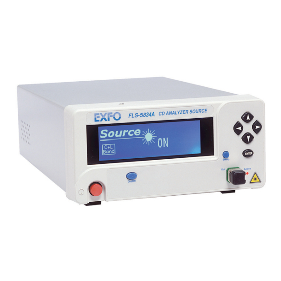
Introducing the FLS-5834A CD/PMD Analyzer Source The FLS-5834A CD/PMD Analyzer Source is a modulated, polarized broadband fiber-optic source that has been especially designed to be used with EXFO FTB-5800 Chromatic Dispersion Analyzer. Front Panel Setup menu access FLS-5834A CD/PMD ANALYZER SOURCE... -
Page 8: Back Panel
The FLS-5834A is compatible with : FTB-5500B PMD Analyzer FTB-5800 Chromatic Dispersion Analyzer MPORTANT Before using the FLS-5834A with the FTB-5800, you must install: ToolBox 6.28 or later. The appropriate product pack (if applicable) If you are using ToolBox 6.28, ensure to install ToolBox FTB-5800 6.28.1.17 Product Pack. -
Page 9: Conventions
Introducing the FLS-5834A CD/PMD Analyzer Source Conventions Conventions Before using the product described in this manual, you should understand the following conventions: ARNING Indicates a potentially hazardous situation which, if not avoided, could result in death or serious injury. Do not proceed unless you understand and meet the required conditions. -
Page 11: Safety Information
Safety Information ARNING Do not install or terminate fibers while a light source is active. Never look directly into a live fiber and ensure that your eyes are protected at all times. ARNING Use of controls, adjustments and procedures for operation and maintenance other than those specified herein may result in hazardous radiation exposure. -
Page 12: Electrical Safety Information
The color coding used in the electric cable depends on the cable. New plugs should meet the local safety requirements and include: adequate load-carrying capacity ground connection cable clamp MPORTANT EXFO assumes no liability if you attempt to perform internal service on this unit. FLS-5834A... - Page 13 Safety Information Electrical Safety Information ARNING Use this unit indoors only. Position the unit so that the air can circulate freely around it. Operation of any electrical instrument around flammable gases or fumes constitutes a major safety hazard. Do not remove unit covers during operation. To avoid electrical shock, do not operate the unit if any part of the outer surface (covers, panels, etc.) is damaged.
- Page 14 Measured in 0 °C to 31 °C (32 °F to 87.8 °F) range, decreasing linearly to 50 % at 40 °C (104 °F). ± Not exceeding 10 % of the nominal voltage. The following label is located on the back panel of the unit: FLS-5834A...
-
Page 15: Getting Started With Your Light Source
Getting Started with Your Light Source Turning On and Off the CD/PMD Analyzer Source ARNING Before turning on the source, please read the Electrical Safety Information on page 6. To turn on and off the CD/PMD Analyzer Source : Press the red button located in the lower left-hand corner of the front panel. -
Page 16: Fls-5834A Cd/Pmd Analyzer Source Display
Getting Started with Your Light Source FLS-5834A CD/PMD Analyzer Source Display FLS-5834A CD/PMD Analyzer Source Display Form the main window of your unit, you can get important information on the source with just one glance. Remote control indicator Source C+ L... -
Page 17: Setting Cd/Pmd Analyzer Source Parameters
Setting CD/PMD Analyzer Source Parameters The blue button on the right side of the display provides access to the single-level Setup menu. You can access the Setup menu even while the source is active. The figure below shows Setup menu items. GPIB Refresh Rate 8 Hz... -
Page 18: Setting The Refresh Rate
3. Press ENTER to access the Refresh Rate edit box. 4. Use the up/down arrow keys to set the refresh rate between 1/2 Hz, 1 Hz, 2 Hz, 4 Hz, 8 Hz and 16 Hz. 5. Press ENTER to confirm the new refresh rate. FLS-5834A... -
Page 19: Setting The Backlight
Setting CD/PMD Analyzer Source Parameters Setting the Backlight Setting the Backlight In certain circumstances, you might want to deactivate the display backlight. To deactivate the backlight: 1. Press the Setup key. 2. Use the up/down or left/right arrow keys to select Backlight (the item will be displayed in reverse video). -
Page 20: Setting The Video Mode
N.A. Video Mode Flow Ctrl N.A. Exit Refresh Rate RS232 / GPIB GPIB 8 Hz Backlight GPIB Addr. Baud Rate Contrast N.A. Baud Rate Video Mode Flow Ctrl N.A. Exit Exit 5. Press ENTER to confirm the video mode. FLS-5834A... -
Page 21: Resetting The Cd/Pmd Analyzer Source
Setting CD/PMD Analyzer Source Parameters Resetting the CD/PMD Analyzer Source Resetting the CD/PMD Analyzer Source You may want to reset the CD/PMD Analyzer Source parameters to their original values. To reset parameters to values at time of purchase, while turning on the unit: Press ENTER until the unit beeps three times. -
Page 23: Operating The Cd/Pmd Analyzer Source
To ensure maximum power and to avoid erroneous readings: Always clean fiber ends as explained below before inserting them into the port. EXFO is not responsible for damage or errors caused by bad fiber cleaning or handling. Ensure that your patchcord has appropriate connectors. Joining mismatched connectors will damage the ferrules. -
Page 24: Installing The Exfo Universal Interface (Eui)
Operating the CD/PMD Analyzer Source Installing the EXFO Universal Interface (EUI) Installing the EXFO Universal Interface (EUI) The EUI fixed baseplate is available for connectors with angled (APC) or non-angled (UPC) polishing.A green border around the baseplate indicates that it is for APC-type connectors. -
Page 25: Activating Or Deactivating The Source
Operating the CD/PMD Analyzer Source Activating or Deactivating the Source Activating or Deactivating the Source To activate the source: 1. Setup the source as explained in Setting CD/PMD Analyzer Source Parameters on page 11. 2. To activate the source, press on the On/Off button. The active LED on the module front will light up, and the front display will read "Source ON", also showing a light beam icon. -
Page 27: Controlling The Source Remotely
Controlling the Source Remotely You can control the CD/PMD Analyzer Source remotely either by: a GPIB interface (through a GPIB cable connected to the GPIB port) an RS-232 interface (through a serial cable connected to the serial port). GPIB port Serial port (RS-232 DTE) Fuse holder MODEL: GO... - Page 28 Specific commands for the CD/PMD Analyzer Source are shown in the Product-Specific Commands—Quick Reference table on page 81. You can find detailed information in the Remonte Control Commands appendix. When the CD/PMD Analyzer Source is remotely controlled, RM appears in the upper right-hand corner of the display. FLS-5834A...
-
Page 29: Setting The Remote Command Mode
Controlling the Source Remotely Setting the Remote Command Mode Setting the Remote Command Mode To remotely control the CD/PMD Analyzer Source, you must set a GPIB address or activate the RS-232 port. To set a remote command mode: 1. Press the Setup key. 2. -
Page 30: Setting The Gpib Address
GPIB Backlight GPIB Addr. Contrast Baud Rate N.A. Video Mode Flow Ctrl N.A. Exit 3. Press ENTER, then use the up/down arrow keys to select a GPIB address between 1 and 30. 4. Press ENTER to confirm your choice. FLS-5834A... -
Page 31: Setting The Baud Rate
Controlling the Source Remotely Setting the Baud Rate Setting the Baud Rate The baud rate is a parameter related to RS-232 communication. It determines the speed at which data is sent between the unit and a computer, in bits per second (bps). To change the baud rate for your remote communications: 1. -
Page 32: Setting The Flow Control
3. Press ENTER, then use the up/down arrow keys to select the type of flow you want. None means no flow control. Soft allows the unit or computer controlling it, to turn the data transmission on or off. 4. Press ENTER to confirm. FLS-5834A... -
Page 33: Communication Parameters
Controlling the Source Remotely Communication Parameters Communication Parameters The communication parameters are used to set the communication port. Note: EOS means “End of String.” EOI means “End or Identify.” For GPIB Communication Terminate Read on EOS Set EOI with EOS on Writes Type of compare on EOS 8 bits EOS byte... -
Page 34: Standard Status Data Structure
The diagram displayed on page 31 is a useful aid in understanding the general commands and how a service request (SRQ) is generated. Standard event status register (ESR) Bits Mnemonics Bit Value Power on Not used Command error Execution error Device dependent error Query error Not used Operation complete FLS-5834A... - Page 35 Controlling the Source Remotely Standard Status Data Structure Standard event status enable register (ESE) Bits Mnemonics Bit Value Power on Not used Command error Execution error Device dependent error Query error Not used Operation complete CD/PMD Analyzer Source...
- Page 36 Message available Not used Error / Event queue Not used Not used Service request enable register (SRE) Bits Mnemonics Bit Value Not used Reserved Event status byte Message available Not used Error / Event queue Not used Not used FLS-5834A...
- Page 37 Controlling the Source Remotely Standard Status Data Structure Standard Event Status Register (ESR) & & & & & & & & Standard Event Status Enable Register (ESE) Message Output Queue not Empty Error / Event Ouput Queue not Empty read by serial poll ESB MAV Status Byte Service Request...
- Page 38 1 and will remain there until read by a serial poll –even if the reason or condition causing the service request no longer exists. Similarly, if a serial poll reads the RQS, it is reset to 0, whether or not the condition causing the service request still exists. FLS-5834A...
-
Page 39: Command Structure
Controlling the Source Remotely Command Structure Command Structure The GPIB and RS-232 commands follow the guidelines determined by the Standard Commands for Programmable Instruments (SCPI) consortium. For example, the following command syntax is used to activate or deactivate the source. SOUR:POW[:STAT]<wsp><Boolean>... -
Page 40: Error Messages Format
Controlling the Source Remotely Error Messages Format Error Messages Format System and device specific errors are managed by the FLS-5834A CD/PMD Analyzer Source. The generic format for error messages is illustrated in the following figure. <Error <Device dependent ” <Error number>... -
Page 41: Maintenance
Maintenance To help ensure long, trouble-free operation: Always clean fiber-optic connectors before using them. Keep the unit free of dust. Clean the unit casing and front panel with a cloth slightly dampened with water. Store unit at room temperature in a clean and dry area. Keep the unit out of direct sunlight. -
Page 42: Cleaning Eui Connectors
3. Slowly insert the cleaning tip into the EUI adapter until it comes out on the other side (a slow clockwise rotating movement may help). 4. Gently turn the cleaning tip one full turn, then continue to turn as you withdraw it. FLS-5834A... - Page 43 6d. Verify connector surface with a portable fiber-optic microscope (e.g., EXFO’s FOMS) or fiber inspection probe (e.g., EXFO’s FIP). ARNING Verifying the surface of the connector WHILE THE UNIT IS ACTIVE WILL result in permanent eye damage.
-
Page 44: Replacing Fuses
Replacing Fuses Replacing Fuses The FLS-5834A CD/PMD Analyzer Source contains two F2.0L250V-type fuses (IEC, 5 mm x 20 mm (0.197 in x 0.787 in), fast-acting, low breaking capacity, 250 V). The fuse holder is located at the back of the CD/PMD Analyzer Source, just beside the power inlet. -
Page 45: Recalibrating The Unit
You should determine the adequate calibration interval for your unit according to your accuracy requirements. Under normal use, EXFO recommends calibrating your unit every year. CD/PMD Analyzer Source... -
Page 46: Upgrading The Embedded Software
Upgrading the Embedded Software Upgrading the Embedded Software To upgrade the CD/PMD Analyzer Source embedded software, you will need to obtain the upgrade files from EXFO’s Technical Support Group. You will also need a null-modem cable. MPORTANT You may upgrade software under DOS, Windows 3.1, Windows 9x, or Windows 2000. - Page 47 Maintenance Upgrading the Embedded Software 7. When a message about waiting for a evice handshake appears, turn on the CD/PMD Analyzer Source. The unit display remains off, the unit beeps once and the upgrade program starts automatically. A progress bar on the computer screen indicates the upgrade status.
-
Page 48: Recycling And Disposal (Applies To European Union Only)
This equipment was sold after August 13, 2005 (as identified by the black rectangle). Unless otherwise noted in a separate agreement between EXFO and a customer, distributor or commercial partner, EXFO will cover costs related to the collection, treatment, recovery and disposal of... -
Page 49: Troubleshooting
Restart your unit to solve the problem. Checksum error while reading the module’s FIFO. Command not accepted: If problem persists, call EXFO for assistance. The command that caused the warning will be lost. The unit may continue with the program even if the command was not performed. - Page 50 CD/PMD Analyzer Source Error Messages Warning/Error Description Recommended Action Number FIFO not ready for reading: If problem persists, call EXFO for assistance. The unit’s FIFO is not ready for reading. Commands sent will be ignored. Laser over-current: Call EXFO for assistance.
- Page 51 Call EXFO for assistance. A problem occurred when accessing the EEPROM memory (read or write). No more room in the command pipe: If problem persists, call EXFO for assistance. A command could not be added to the command pipe. Timeout error: Call EXFO for assistance.
- Page 52 Array boundary error: Restart your unit to solve the problem. A table index is outside the boundaries set by the array. 32305 Invalid Opcode: Restart your unit to solve the problem. The unit did not recognize the binary code. FLS-5834A...
-
Page 53: Gpib Troubleshooting
Troubleshooting GPIB Troubleshooting GPIB Troubleshooting Problem Probable Cause Solution Unable to communicate Incorrect Select the correct with CD/PMD Analyzer communication type communication type: RS-232 or Source (no response from selected. GPIB. *IDN? command). Incorrect Check the communication communication parameters: bus address, baud parameters. -
Page 54: Finding Information On The Exfo Web Site
Troubleshooting Finding Information on the EXFO Web Site Finding Information on the EXFO Web Site The EXFO Web site provides answers to frequently asked questions (FAQs) regarding the use of your FLS-5834A CD/PMD Analyzer Source. To access FAQs: 1. Type http://www.exfo.com... -
Page 55: Contacting The Technical Support Group
Contacting the Technical Support Group To obtain after-sales service or technical support for this product, contact EXFO at one of the following numbers. The Technical Support Group is available to take your calls from Monday to Friday, 7:30 a.m. to 8:00 p.m. -
Page 56: Transportation
Pack the unit in its original packing material when shipping. Avoid high humidity or large temperature fluctuations. Keep the unit out of direct sunlight. Avoid unnecessary shocks and vibrations. FLS-5834A... -
Page 57: Warranty
EXFO Electro-Optical Engineering Inc. (EXFO) warrants this equipment against defects in material and workmanship for a period oftwo years from the date of original shipment. EXFO also warrants that this equipment will meet applicable specifications under normal use. During the warranty period, EXFO will, at its discretion, repair, replace,... -
Page 58: Liability
Liability Liability EXFO shall not be liable for damages resulting from the use of the product, nor shall be responsible for any failure in the performance of other items to which the product is connected or the operation of any system of which the product may be a part. -
Page 59: Service And Repairs
5. Return the equipment, prepaid, to the address given to you by support personnel. Be sure to write the RMA number on the shipping slip. EXFO will refuse and return any package that does not bear an RMA number. -
Page 60: Exfo Service Centers Worldwide
Warranty EXFO Service Centers Worldwide EXFO Service Centers Worldwide If your product requires servicing, contact your nearest authorized service center. EXFO Headquarters Service Center 400 Godin Avenue 1 866 683-0155 (USA and Canada) Quebec (Quebec) G1M 2K2 Tel.: 1 418 683-5498... -
Page 61: A Technical Specifications
The following technical specifications can change without notice. The information presented in this section is provided as a reference only. To obtain this product’s most recent technical specifications, visit the EXFO Web site at www.exfo.com. SPECIFICATIONS SPECIFICATIONS Center wavelength (nm) 1580 ±20... -
Page 63: B Rackmount Installation
Rackmount Installation You can place your FLS-5834A CD/PMD Analyzer Source in a rackmount to facilitate its usage. To install the rackmount: 1. Fix the angle iron using four flat Phillips screws. 2. Fix the rackmount bracket to the frame using two round Phillips screws. - Page 64 Rackmount Installation To install your FLS-5834A CD/PMD Analyzer Source in a rackmount: 1. Slide the benchtop unit into the rackmount and tighten it from underneath using the four cover fixing screws. If measurement X on the illustration exceeds 11.125 in., fix the unit into the four holes identified as A.
-
Page 65: C Remote Control Commands
Remote Control Commands IEEE 488.2 Commands—Quick Reference The CD/PMD Analyzer Source recognizes the required commands identified in IEEE 488.2. The table below summarizes these commands. Command Function *CLS Clear status command *ESE Standard event status enable command *ESE? Standard event status enable query *ESR? Standard event status register query *IDN? -
Page 66: Ieee 488.2 Commands-Description
Standard Event Status Enable Register N.U. N.U. Syntax *ESE<wsp><RegisterValue> Parameter(s) RegisterValue: The program data syntax for <RegisterValue> is defined as a <DECIMAL NUMERIC PROGRAM DATA> element. The <RegisterValue>, expressed in base 2, represents the bit values of the Standard Event Status Enable Register. FLS-5834A... - Page 67 Remote Control Commands IEEE 488.2 Commands—Description *ESE The table below shows the contents of this register. Bit Weight Meaning PON 128 Power ON Enable N.U. 64 Not used CMD 32 CoMmanD Error Enable EXE 16 Execution Error Enable DDE 8 Device Dependent Error Enable QRY 4 QueRry Error Enable...
- Page 68 The *ESE? query allows the programmer to determine the current contents of the Standard Event Status Enable Register. See the contents of this register below. Standard Event Status Enable Register N.U. N.U. Syntax *ESE? Parameter(s) None Response Syntax <RegisterValue> FLS-5834A...
- Page 69 Remote Control Commands IEEE 488.2 Commands—Description *ESE? Response(s) RegisterValue: The response data syntax for <RegisterValue> is defined as a <NR1 NUMERIC RESPONSE DATA> element. The <RegisterValue> ranges from 0 through 255. The <RegisterValue> value expressed in base 2 (binary) represents the bit values of the Standard Event Status Enable register.
- Page 70 Standard Event Status Register. Reading the Standard Event Status Register clears it. See the contents of this register below. Standard Event Status Enable Register N.U. N.U. Syntax *ESR? Parameter(s) None Response Syntax <RegisterValue> FLS-5834A...
- Page 71 Remote Control Commands IEEE 488.2 Commands—Description *ESR? Response(s) RegisterValue: The response data syntax for <RegisterValue> is defined as a <NR1 NUMERIC RESPONSE DATA> element. The <RegisterValue> ranges from 0 through 255. The <RegisterValue> value expressed in base 2 (binary) represents the bit values of the Standard Event Status register.
- Page 72 The intent of the *IDN? query is for the unique identification of devices over the system interface. Syntax *IDN? Response(s) “EXFO E.-O. Engineering,FLS-5834A,xxxxxxxxxx, 2.0r0”, where – xxxxxxxx is the serial number – 2.0r0 is the Firmware level. *LOK Description This command is used to set the Remote Lockout programming state.
- Page 73 Remote Control Commands IEEE 488.2 Commands—Description *LOK Example(s) *LOK 1 Notes This command can only be used when working with RS-232 communication. See Also *LOK? CD/PMD Analyzer Source...
- Page 74 The <LockoutState> response corresponds to the remote lockout state of the CD/PMD Analyzer Source: “0”- The source is unlocked. “1”- The source is locked. Example(s) *LOK? returns 1 Notes This command can only be used when working with RS-232 communication. See Also *LOK FLS-5834A...
- Page 75 Remote Control Commands IEEE 488.2 Commands—Description *OPC Description The *OPC command allows synchronization between the instrument and an external controller. The *OPC command causes the instrument to set bit 0 (Operation Complete) in the Standard Event Status Register to the TRUE (logic 1) state when the instrument completes all pending operations.
- Page 76 <NR1 NUMERIC RESPONSE DATA> element. The <Acknowledge> response is a single ASCII-encoded byte corresponding to 1. The receipt of an <Acknowledge> response indicates that all pending selected device operations have been completed. Example(s) *OPC? Return 1 See Also *OPC *WAI FLS-5834A...
- Page 77 Remote Control Commands IEEE 488.2 Commands—Description *REM Description This command is used to set the Remote programming state that determines if the source will be controlled locally or remotely. Syntax *REM<wsp><RemoteState> Parameter(s) RemoteState: The program syntax data for <RemoteState> is defined as a <Boolean Program Data>...
- Page 78 Any Event Enable Register setting, including the Standard Event Status Enable Register setting. d) Any Event Register setting, including the Standard Event Status Register settings. e) Calibration data that affects device specifications. f) The Service Request Enable Register setting. Syntax *RST Parameter(s) None FLS-5834A...
- Page 79 Remote Control Commands IEEE 488.2 Commands—Description *SRE Description The *SRE command sets the Service Request Enable Register bits. See the contents of this register below. This register contains a mask value to enable the bits in the Status Byte Register. Serv ic e R eques t Enable R egis ter N.U.
- Page 80 Error / Event AVailable Enable N.U. 2 Not used N.U. 1 Not used A bit value of zero shall indicate a disabled condition. Example(s) *SRE 52 where 52 = (bit ESB, bit MAV and bit EAV) See Also *SRE? *STB? FLS-5834A...
- Page 81 Remote Control Commands IEEE 488.2 Commands—Description *SRE? Description The *SRE? query allows the programmer to determine the current contents of the Service Request Enable Register. See the contents of this register below. Serv ic e R eques t Enable R egis ter N.U.
- Page 82 <NR1 NUMERIC RESPONSE DATA> element. The <RegisterValue> ranges from 0 through 255. When converted to binary (base 2), the <RegisterValue> represents the current bit values of the Service Request Enable Register. Example(s) *SRE Return 32 (bit ESB) See Also *SRE *STB? FLS-5834A...
- Page 83 Remote Control Commands IEEE 488.2 Commands—Description *STB? Description The *STB? query allows the programmer to read the status byte and Master Summary Status bit. See the content of this register below. Status By te R egister R QS/ N.U. N.U. N.U.
- Page 84 MAV 16 Message AVailable Enable N.U. 8 Not used EAV 4 Error / Event AVailable Enable N.U. 2 Not used N.U. 1 Not used Example(s) *STB? Return 68 where 68 = (bit MSS and bit EAV) See Also *SRE *SRE? FLS-5834A...
- Page 85 Remote Control Commands IEEE 488.2 Commands—Description *TST? Description This query returns a binary value indicating the test results. Syntax *TST? Response Result: The response data syntax for <Result> is defined as a <NR1 NUMERIC RESPONSE DATA> element. A decimal value indicating the sum of all corresponding errors: “0”–No errors “1”–N/A...
- Page 86 Remote Control Commands IEEE 488.2 Commands—Description *WAI Description The *WAI command shall prevent the device from executing any further commands or queries until the no-operation-pending flag becomes TRUE. Syntax *WAI Parameter(s) None Example(s) *WAI See Also *OPC *OPC? FLS-5834A...
-
Page 87: Product-Specific Commands-Quick Reference
Remote Control Commands Product-Specific Commands—Quick Reference Product-Specific Commands—Quick Reference The table below summarizes commands specific to the CD/PMD Analyzer Source. Parameter/ Command Description Response DISP BRIG <numeric_value> Turn backlight on or off |MINimum| MAXimum BRIG? (0|1) Backlight on or off? SOUR STAT 0|1 |ON|OFF... -
Page 88: Product-Specific Commands-Description
“1”–turns the backlight on “0”–turns the backlight off Example DISP:BRIG 1 DISPLAY:BRIGHTNESS 0 DISPlay:BRIGhtness? Description This command returns the state of the backlight. Syntax DISP:BRIG? Response A numeric value: “1”-the backlight is on “0”-the backlight is off Example DISP:BRIG? 1 FLS-5834A... - Page 89 Remote Control Commands Product-Specific Commands-Description SOURce:POWer[:STATe] Description This command turns on or off the source. When the source is on, the red LED on the front of the module illuminates. Syntax SOUR:POW[:STAT]<wsp><boolean>|ON|OFF Parameters A boolean parameter: “1”–turns the source on “0”–turns the source off Example SOUR:POW:STAT 1 (turns the source on.)
- Page 90 Description This query reads the CD/PMD Analyzer Source identification string. Syntax SYST:VERS? Response “EXFO E.-O. Eng. FLS-5834A vx.xx”xxxxxxxx xxxxxxx, where xxxxxxxx xxxxxxx is the serial number and vx.xx is the current product version. Note This query returns the same response as the *IDN? query.
-
Page 91: Dscpi-Based Errors
SCPI-Based Errors Error Description Probable Cause Number -100 “Command error” A command error has occurred. This is the generic syntax error for devices that cannot detect more specific errors. -104 “Data type error” The parser recognized a data element different than the one allowed. -108 “Parameter not allowed”... - Page 92 -365 “Time out error” This is a generic device-dependent error. -400 “Query error” A query error occurred. This is the generic syntax error for devices that cannot detect more specific errors. FLS-5834A...
-
Page 93: Index
Index Index IEEE 488.2, quick reference....59 RS-232 ........... 33 AC requirements ........... 8 commands, specific ........81 address, GPIB ..........24 common commands........59 adjusting contrast ........13 communication after-sales service ........49 parameters..........27 speed ............. 25 configuring display ........ 13, 14 connector pinout configuration.... - Page 94 ......... 18 GPIB commands...........81 dust cap..........18 ground.............2, 21 EUI connectors, cleaning ......36 EXFO service centers........54 EXFO universal interface. see EUI handshake, software........26 EXFO Web site..........48 identification label ........49 FAQs............48 IEEE 488.2 commands......59, 60 fiber ends, cleaning........
- Page 95 Index port GPIB ...........2, 21 label, identification ........49 serial..........2, 21, 22 label, safety ........... 5 power locked keyboard .......... 10 cable............6 inlet ............2, 21 on/off ............9 main window ..........10 plug............6 maintenance power source, AC...........8 EUI connectors........36 problems with GPIB ........47 front panel..........
- Page 96 ..........11 RS-232 refresh rate..........12 commands..........59 video mode ..........14 connector pinout configuration..... 22 setup button ..........11 for software upgrade......40 shipping to EXFO .........53 mode ............. 23 software port ............23 handshake..........26 speed............. 25 upgrade..........40 RS-232 commands ........81 source rules, SCPI ...........
- Page 97 Index unit covers ............7 disconnecting .......... 6 installing..........7 powering ..........9 repairing ..........7 ventilation ..........7 unit recalibration......... 39 upgrading the software ......40 using source ..........17 value, defining ..........11 ventilation ............. 7 video mode default ...........
- Page 98 EXFO ASIA-PACIFIC 151 Chin Swee Road SINGAPORE 169876 #03-29, Manhattan House Tel.: +65 6333 8241 · Fax: +65 6333 8242 TOLL-FREE (USA and Canada) 1 800 663-3936 © 2007 EXFO Electro-Optical Engineering Inc. All rights reserved. Printed in Canada (2007-11)
Need help?
Do you have a question about the FLS-5834A and is the answer not in the manual?
Questions and answers