Table of Contents
Advertisement
Quick Links
Advertisement
Table of Contents

Related Manuals for EXFO FTB-5240S


Summary of Contents for EXFO FTB-5240S
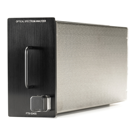
- Page 1 User Guide FTB-5240S/5240BP Optical Spectrum Analyzer for FTB-500...
- Page 2 EXFO Inc. (EXFO). Information provided by EXFO is believed to be accurate and reliable. However, no responsibility is assumed by EXFO for its use nor for any infringements of patents or other rights of third parties that may result from its use.
-
Page 3: Table Of Contents
Contents Contents Certification Information ....................... vi 1 Introducing the FTB-5240S/5240BP Optical Spectrum Analyzer ....1 Models ............................2 Typical Applications ........................3 Conventions ..........................4 2 Safety Information ..................5 3 Getting Started with Your Optical Spectrum Analyzer ......7 Inserting and Removing Test Modules ..................7 Starting the Optical Spectrum Analyzer Application .............12... - Page 4 Recycling and Disposal (Applies to European Union Only) ..........425 13 Troubleshooting ..................427 Viewing Online Documentation ..................427 Contacting the Technical Support Group ................427 About ..........................428 Transportation ........................430 14 Warranty ....................431 General Information ......................431 Liability ..........................432 Exclusions ...........................433 Certification ........................433 Service and Repairs ......................434 EXFO Service Centers Worldwide ..................435 FTB-5240S/5240BP...
- Page 5 Contents A Technical Specifications ................437 B SCPI Command Reference ............... 439 Quick Reference Command Tree ..................440 Product-Specific Commands—Description ................443 C Formulas Used with Your Optical Spectrum Analyzer ......519 EDFA Noise Figure Calculation ....................519 Central Wavelength Calculation (Spectral Transmittance) ...........520 Bandwidth Calculation (Spectral Transmittance) ..............521 Index ......................
-
Page 6: Certification Information
F.C.C. Information Electronic test equipment is exempt from Part 15 compliance (FCC) in the United States. However, compliance verification tests are systematically performed on most EXFO equipment. Information Electronic test equipment is subject to the EMC Directive in the European Union. - Page 7 Application of Council Directive(s): 2006/95/EC - The Low Voltage Directive 2004/108/EC - The EMC Directive 93/68/EEC - CE Marking And their amendments Manufacturer’s Name: EXFO Electro-Optical Engineering Inc. Manufacturer’s Address: 400 Godin Avenue Quebec, Quebec Canada, G1M 2K2 (418) 683-0211 Equipment Type/Environment: Test &...
-
Page 9: Introducing The Ftb-5240S/5240Bp Optical Spectrum Analyzer
Optical Signal to Noise Ratio (OSNR) measurement for ROADM and 40 Gbit/s signals and networks. The FTB-5240S is an expert DWDM OSA that is designed for efficient commissioning, maintenance and trouble-shooting of DWDM components and links in the field, from 50 GHz to CWDM network. -
Page 10: Models
Models Models The Optical Spectrum Analyzer comes in different models: FTB-5240S: The FTB-5240S is a small form factor expert OSA (two-slot unit). It offers new modulation schemes, such as non-return-to-zero (NRZ), duo binary, differential phase-shift keying (DPSK), quadrature phase shift keying (QPSK), which present large line widths and often display multiple peaks. -
Page 11: Typical Applications
Introducing the FTB-5240S/5240BP Optical Spectrum Analyzer Typical Applications Typical Applications You can use your Optical Spectrum Analyzer for the following tasks: Characterizing channels in the O- to U-band spectra Testing laser sources for spectral purity and power distribution Testing the transmission characteristics of optical devices... -
Page 12: Conventions
Introducing the FTB-5240S/5240BP Optical Spectrum Analyzer Conventions Conventions Before using the product described in this manual, you should understand the following conventions: ARNING Indicates a potentially hazardous situation which, if not avoided, could result in death or serious injury. Do not proceed unless you understand and meet the required conditions. -
Page 13: Safety Information
Safety Information ARNING Do not install or terminate fibers while a light source is active. Never look directly into a live fiber and ensure that your eyes are protected at all times. ARNING Use of controls, adjustments and procedures for operation and maintenance other than those specified herein may result in hazardous radiation exposure or impair the protection provided by this unit. -
Page 15: Getting Started With Your Optical Spectrum Analyzer
Getting Started with Your Optical Spectrum Analyzer Inserting and Removing Test Modules AUTION Never insert or remove a module while the FTB-500 is turned on. This will result in immediate and irreparable damage to both the module and unit. ARNING When the laser safety LED ( ) is flashing on the FTB-500, at least one of your modules is emitting an optical signal. - Page 16 4. Insert the protruding edges of the module into the grooves of the receptacle’s module slot. 5. Push the module all the way to the back of the slot, until the retaining screw makes contact with the receptacle casing. 6. Place the FTB-500 so that its left panel is facing you. FTB-5240S/5240BP...
- Page 17 Getting Started with Your Optical Spectrum Analyzer Inserting and Removing Test Modules 7. While applying slight pressure to the module, turn the retaining screw clockwise until it is tightened. This will secure the module into its “seated” position. Turn retaining screw knob clockwise FTB-500 left panel When you turn on the unit, the startup sequence will automatically detect...
- Page 18 2. Position the FTB-500 so that the left panel is facing you. 3. Turn the retaining screw counterclockwise until it stops. The module will be slowly released from the slot. Turn retaining screw knob(s) counterclockwise FTB-500 left panel 4. Place the FTB-500 so that the right panel is facing you. FTB-5240S/5240BP...
- Page 19 Getting Started with Your Optical Spectrum Analyzer Inserting and Removing Test Modules 5. Hold the module by its sides or by the handle (NOT by the connector) and pull it out. Optical Spectrum Analyzer...
-
Page 20: Starting The Optical Spectrum Analyzer Application
Starting the Optical Spectrum Analyzer Application Starting the Optical Spectrum Analyzer Application Your FTB-5240S/5240BP Optical Spectrum Analyzer module can be configured and controlled from its dedicated ToolBox application. Note: For details about ToolBox, refer to the FTB-500 user guide. To start the application: 1. - Page 21 Getting Started with Your Optical Spectrum Analyzer Starting the Optical Spectrum Analyzer Application The main window (shown below) contains all the commands required to control the Optical Spectrum Analyzer: Display panes Function buttons Result panes MPORTANT For optimal test results, you must allow a minimum warm up period of two hours for your Optical Spectrum Analyzer before starting your tests.
-
Page 22: Exiting The Application
Current date and time Battery indicator Module status For more information about automating or remotely controlling the FTB-5240S/5240BP Optical Spectrum Analyzer, refer to the FTB-500 user guide. Exiting the Application Closing any application that is not currently being used helps freeing system memory. -
Page 23: Preparing Your Optical Spectrum Analyzer For A Test
To ensure maximum power and to avoid erroneous readings: Always inspect fiber ends and make sure that they are clean as explained below before inserting them into the port. EXFO is not responsible for damage or errors caused by bad fiber cleaning or handling. - Page 24 If your connector features a screwsleeve, tighten the connector enough to firmly maintain the fiber in place. Do not overtighten, as this will damage the fiber and the port. Note: If your fiber-optic cable is not properly aligned and/or connected, you will notice heavy loss and reflection. FTB-5240S/5240BP...
-
Page 25: Installing The Exfo Universal Interface (Eui)
Preparing Your Optical Spectrum Analyzer for a Test Installing the EXFO Universal Interface (EUI) Installing the EXFO Universal Interface (EUI) The EUI fixed baseplate is available for connectors with angled (APC) or non-angled (UPC) polishing. A green border around the baseplate indicates that it is for APC-type connectors. -
Page 26: Selecting A Test Mode
Spectral Transmittance: Allows you to characterize the spectral transmittance of optical components such as filters. EDFA: Allows you to characterize the performance of an Erbium Doped Fiber Amplifier (EDFA) using the OSA module in field deployed systems (NB measurement assumes transmission conditions). FTB-5240S/5240BP... - Page 27 Preparing Your Optical Spectrum Analyzer for a Test Selecting a Test Mode To select a test mode: 1. From the main menu, press Mode. Optical Spectrum Analyzer...
- Page 28 Setting Up the Instrument in Drift Mode on page 103, Setting Up the Instrument in DFB Mode on page 165, Setting Up the Instrument in Spectral Transmittance Mode on page 183 and Setting Up the Instrument in EDFA Mode on page 209. FTB-5240S/5240BP...
-
Page 29: Nulling Electrical Offsets
Temperature and humidity variations affect the performance of electronic circuits and optical detectors. For this reason, EXFO recommends performing a nulling of the electrical offsets whenever environmental conditions change. - Page 30 Nulling Electrical Offsets 3. Press Nulling. You are notified that the nulling is in progress in the status bar. Nulling should be completed in a few seconds. Note: The Start and Discover options are not available during the nulling process. FTB-5240S/5240BP...
-
Page 31: Performing User Calibration
Preparing Your Optical Spectrum Analyzer for a Test Performing User Calibration Performing User Calibration Calibrating your module can help you achieve better results. It is particularly important when the measurement accuracy is critical or when your OSA has experienced unusual shock or vibrations. To reach the highest possible accuracy, you can perform a wavelength or power calibration. - Page 32 Write new correction factors inside the module Load the text file built at preceding step Press Write to Module. The application shows a warning message indicating to clear correction factors before making new measurements Verify that calibration points are properly applied. FTB-5240S/5240BP...
- Page 33 Preparing Your Optical Spectrum Analyzer for a Test Performing User Calibration An example of the calibration file format is given below. 1310.154; 1310.167; -1.34; -1.55 1490.000; 1490.000; 1.09; 1.15 1551.334; 1551.298; -5.20; -5.45 1625.401; 1625.448; 0.00; 0.00 Note: The decimal separator is a point ( . ). This decimal separator is constant independent of what the regional settings are.
- Page 34 2. Select the Calibration tab. Note: You cannot edit the power or wavelength values directly from the application. The modifications in the user calibration have to be made in a text file, and then it can be loaded in the application. FTB-5240S/5240BP...
- Page 35 Preparing Your Optical Spectrum Analyzer for a Test Performing User Calibration 3. If a user calibration file exists, press Load Factors to load the file. 4. Select the modified user calibration file and press Open. Optical Spectrum Analyzer...
- Page 36 Preparing Your Optical Spectrum Analyzer for a Test Performing User Calibration The calibration values will replace the Correction factors list in the Analysis setup - Calibration window. FTB-5240S/5240BP...
- Page 37 Preparing Your Optical Spectrum Analyzer for a Test Performing User Calibration 5. Press Write to Module to apply the modified calibration values to the module. Optical Spectrum Analyzer...
- Page 38 Performing User Calibration 6. To verify that the calibration changes are properly applied to the module, press Load from Module. Note: OK and Cancel buttons do not have any impact on the calibration page or the correction factors inside the module. FTB-5240S/5240BP...
- Page 39 Preparing Your Optical Spectrum Analyzer for a Test Performing User Calibration To clear user correction factors: 1. From the Main Menu, press Analysis Setup. Optical Spectrum Analyzer...
- Page 40 Preparing Your Optical Spectrum Analyzer for a Test Performing User Calibration 2. Select the Calibration tab. FTB-5240S/5240BP...
- Page 41 Preparing Your Optical Spectrum Analyzer for a Test Performing User Calibration 3. Press Clear user correction factors, to load the factory calibration values. Note: The application will ask if you want to clear user correction factors on the module and the user calibration will be removed. Press Yes or No as required.
- Page 42 Preparing Your Optical Spectrum Analyzer for a Test Performing User Calibration To save a user calibration: 1. From the Main Menu, press Analysis Setup. FTB-5240S/5240BP...
- Page 43 Preparing Your Optical Spectrum Analyzer for a Test Performing User Calibration 2. Select the Calibration tab. Optical Spectrum Analyzer...
- Page 44 Preparing Your Optical Spectrum Analyzer for a Test Performing User Calibration 3. Press Save Factors, to save the modified user calibration values. FTB-5240S/5240BP...
-
Page 45: Setting Up The Instrument In Wdm Mode
Setting Up the Instrument in WDM Mode Before performing a spectral analysis in the WDM mode, you must set up your OSA module and the test application with the appropriate parameters, as explained in this chapter. Select the WDM test mode as explained in Selecting a Test Mode on page 18 before setting up the WDM test parameters. - Page 46 Channel Results and Global Results tabs, apply those changes to the analysis setup to use it for future measurements, and re-analyze the trace with those parameters. This is explained in Changing Active Trace Analysis Parameters and Re-analyzing on page 306. FTB-5240S/5240BP...
-
Page 47: Defining Preferences
Setting Up the Instrument in WDM Mode Defining Preferences Defining Preferences The preferences window allows you to set general information and comments on trace, set display parameters and customize the WDM results table. This information is saved with all the traces. Defining Trace Information The trace information relates to the description of the job to be done, cable and job IDs, and any relevant information about what is being tested. - Page 48 2. Select the General tab. 3. Define the general parameters as needed. 4. Press OK to save the changes and close the window, or press Cancel to exit without saving. Press Clear to clear all the changes made in the General tab. FTB-5240S/5240BP...
- Page 49 Setting Up the Instrument in WDM Mode Defining Preferences To enter link and location information: 1. From the Main Menu, press Preferences. 2. Select the Information tab. Optical Spectrum Analyzer...
- Page 50 Description: Enter the description of location if required. 5. Press OK to save the changes and close the window, or press Cancel to exit without saving. Press Restore Defaults to remove all the changes and apply the default values. FTB-5240S/5240BP...
- Page 51 Setting Up the Instrument in WDM Mode Defining Preferences To enter comments: 1. From the Main Menu, press Preferences. Optical Spectrum Analyzer...
- Page 52 2. Select the Comments tab. 3. Enter your comments for the current trace. 4. Press OK to save the changes and close the window, or press Cancel to exit without saving. Press Clear to clear all the changes made in the Comments tab. FTB-5240S/5240BP...
- Page 53 Setting Up the Instrument in WDM Mode Defining Preferences Defining Display Parameters The application allows you to set display settings for the acquisition trace. You can set the spectral unit for the trace and the results table. You can also select the label that should appear on the peaks of the trace.
- Page 54 Setting Up the Instrument in WDM Mode Defining Preferences 2. Select the Display tab. FTB-5240S/5240BP...
- Page 55 Setting Up the Instrument in WDM Mode Defining Preferences 3. Select the spectral unit you want to work with. With the nanometer (nm) spectral unit, the trace will appear as shown below: With the terahertz (THz) spectral unit, the trace will appear as shown below: Optical Spectrum Analyzer...
- Page 56 Setting Up the Instrument in WDM Mode Defining Preferences 4. Select the label that will appear on the peaks in the graph. FTB-5240S/5240BP...
- Page 57 Setting Up the Instrument in WDM Mode Defining Preferences Note: The channel name and channel number cannot be shown at the same time. If a number is displayed on the peak, it means that the channel name for that peak is not defined. If a channel name is defined for the peak, it will be displayed at the top of the peak.
- Page 58 5. Select Show to display the empty channels from the channel list in the Results tab. If Hide is selected, it will not display the empty channels in the Results tab. 6. Select Show to enable horizontal markers in the Markers tab. If Hide is selected, horizontal markers will be disabled. FTB-5240S/5240BP...
- Page 59 Setting Up the Instrument in WDM Mode Defining Preferences 7. Select the background color scheme for Graph as desired. 8. Press OK to save the changes and close the window, or press Cancel to exit without saving. Press Restore Defaults to remove all the changes and apply the default values.
- Page 60 Defining Preferences Customizing WDM Results Table It is possible to select which results you would like to be displayed in the Results tab of your WDM tests. To customize the results table: 1. From the Main Menu, press Preferences. FTB-5240S/5240BP...
- Page 61 Setting Up the Instrument in WDM Mode Defining Preferences 2. Select the WDM Results tab. 3. Select which parameters you want to display in the Results tab from the list of available choices: Name: indicates the name of channel. Center wavelength/frequency: indicates the spectral center-of-mass for the peak in that channel.
- Page 62 4. Press Up or Down to change the order in which the columns will appear in the Results tab. 5. Press OK to save the changes and close the window, or press Cancel to exit without saving. Press Restore Defaults to remove all the changes and apply the default values. FTB-5240S/5240BP...
- Page 63 Setting Up the Instrument in WDM Mode Defining Preferences Customizing WDM File Name The application shall provide a way to define the name of the next file to be saved. Defining a file autonaming format will allow you to quickly and automatically name traces in a sequential order.
- Page 64 Cable ID: indicates the prefix value for the cable ID configured in the Preferences-General tab. Fiber ID: indicates the prefix value for the fiber ID configured in the Preferences-General tab. Location description: indicates the location description provided in the Preferences-Information tab. FTB-5240S/5240BP...
- Page 65 Setting Up the Instrument in WDM Mode Defining Preferences 4. Press Up or Down to change the order in which the field values will appear in the file name. Based on the fields selected, a preview of the file name shall be displayed under File name preview.
-
Page 66: Setting Up Wdm Analysis Parameters
Note: The analysis setup parameters will be applied to the global results and channel results, upon the next acquisition. However, you can also apply the modifications to the active trace in order to re-analyze it. FTB-5240S/5240BP... - Page 67 Setting Up the Instrument in WDM Mode Setting Up WDM Analysis Parameters Defining General Settings The general analysis parameters for WDM acquisitions affect the calculation of the results. These calculations take place after an acquisition. If these settings are modified, they will be applied to the next acquisition.
- Page 68 Setting Up the Instrument in WDM Mode Setting Up WDM Analysis Parameters 2. Select the General tab. FTB-5240S/5240BP...
- Page 69 Setting Up the Instrument in WDM Mode Setting Up WDM Analysis Parameters 3. Under Default channel settings, define the following parameters as needed: Clear the Activate default channel selection, to use the currently defined channel for analysis. This reduces the analysis time by eliminating the peak detection over the complete spectral range.
- Page 70 Total channel power: The total channel power represents the sum of the power values included inside the channel width (including noise). FTB-5240S/5240BP...
- Page 71 Setting Up the Instrument in WDM Mode Setting Up WDM Analysis Parameters Noise for OSNR: indicates which calculation method to use for OSNR value. Fixed range IEC based (IEC): The IEC method uses the interpolation of noise measured on both sides of the signal to estimate the noise level.
- Page 72 Wavelength offset (nm): indicates the offset value applied on the wavelength. You can use an offset to adjust your unit. This does not replace a calibration performed at EXFO, but it can help you achieve the specifications if you have determined that, for example, your modules are used beyond the normal allowed use.
- Page 73 Setting Up the Instrument in WDM Mode Setting Up WDM Analysis Parameters 5. If you want to apply the above settings to the active trace, select the Apply to active trace and re-analyze option and press OK. 6. Press OK to save the changes and close the window, or press Cancel to exit without saving.
- Page 74 This threshold limit option is available in the Channel Parameters tab of Channel Results window only. When this limit is set, the defaults set for the default channels in the Analysis Setup tab will be applied to the channel. FTB-5240S/5240BP...
- Page 75 Setting Up the Instrument in WDM Mode Setting Up WDM Analysis Parameters Defining Global Thresholds Global thresholds will be applied to the global results during the next acquisition. However, any modifications made in the global thresholds parameters can also be applied to the active trace for re-analysis. The application allows you to activate and deactivate the threshold functionality with a single control.
- Page 76 Setting Up the Instrument in WDM Mode Setting Up WDM Analysis Parameters To define global thresholds: 1. From the Main Menu, press Analysis Setup. 2. Select the Global Thresholds tab. FTB-5240S/5240BP...
- Page 77 Setting Up the Instrument in WDM Mode Setting Up WDM Analysis Parameters 3. Select the Activate all thresholds option, to manually set the global threshold values. If this option is not selected, all the thresholds will be deactivated, results are displayed without a Pass/Fail status and Global pass/fail status will not be active in the Global Results tab.
- Page 78 Apply to active trace and re-analyze option and press OK. 6. Press OK to save the changes and close the window, or press Cancel to exit without saving. Press Restore Defaults to remove all the changes and apply the default values. FTB-5240S/5240BP...
- Page 79 Setting Up the Instrument in WDM Mode Setting Up WDM Analysis Parameters Defining Default Thresholds Default thresholds will be applied to any channel found outside the channel list during the next acquisition. Note: The default thresholds settings are enabled only when the Activate all thresholds option is selected in the Global Thresholds tab.
- Page 80 OSNR (dB): is the Optical Signal to Noise Ratio, given by Signal power (according to the current calculation method, in dBm) minus Noise (according to the current calculation method, in dBm). Noise (dBm): indicates the level of the noise for the selected channel. FTB-5240S/5240BP...
- Page 81 Setting Up the Instrument in WDM Mode Setting Up WDM Analysis Parameters 4. If you want to apply the above settings to the active trace, select the Apply to active trace and re-analyze option and press OK. 5. Press OK to save the changes and close the window, or press Cancel to exit without saving.
- Page 82 0.001 nm (approximately) of wavelength range is common between the two channels. To add a channel list: 1. From the Main Menu, press Analysis Setup. FTB-5240S/5240BP...
- Page 83 Setting Up the Instrument in WDM Mode Setting Up WDM Analysis Parameters 2. Select the Channels tab. 3. By default, the channel list is empty. Press Add Channels. 4. Enter values in the boxes as explained below: Start range (nm or THz): indicates the starting range of the channel list.
- Page 84 Note: A warning message will be displayed if any channels are overlapping, but the analysis can still be performed on overlapping channels. If any duplicate channels are added, a confirmation message will be displayed to overwrite the existing channels with the duplicate channels. FTB-5240S/5240BP...
- Page 85 Setting Up the Instrument in WDM Mode Setting Up WDM Analysis Parameters 6. If you want to apply the above settings to the active trace, select the Apply to active trace and re-analyze option. 7. Press OK to save the changes and close the window, or press Cancel to exit without saving.
- Page 86 Setting Up the Instrument in WDM Mode Setting Up WDM Analysis Parameters To edit the parameters of a specific channel: 1. From the Main Menu, press Analysis Setup. FTB-5240S/5240BP...
- Page 87 Setting Up the Instrument in WDM Mode Setting Up WDM Analysis Parameters 2. Select the Channels tab. 3. Select the channel or channels to be modified in the channel list. Selected channels have a in the first column of the channels table. If you want the changes to be applied to all of your channels, press Select All.
- Page 88 Setting Up the Instrument in WDM Mode Setting Up WDM Analysis Parameters 4. Press Edit Selection. FTB-5240S/5240BP...
- Page 89 Setting Up the Instrument in WDM Mode Setting Up WDM Analysis Parameters 5. Modify the settings as needed. For more information about the settings, see Adding Channels on page 74, Changing Default Channel Parameters on page 309 and Defining Default Thresholds on page 71. If you leave a box empty, it will remain as it was before your changes.
- Page 90 7. If you want to apply the above settings to the active trace, select the Apply to active trace and re-analyze option in the Channels window and press OK. 8. Press OK to save the changes and close the window, or press Cancel to exit without saving. FTB-5240S/5240BP...
- Page 91 Setting Up the Instrument in WDM Mode Setting Up WDM Analysis Parameters To add current peaks: Note: You can add current peaks to the channel list only if an acquisition has already been performed. 1. From the Main Menu, press Analysis Setup. Optical Spectrum Analyzer...
- Page 92 OK to close the warning window. Note: Changes can be applied to any channel at any time. Note: If some channels were already present in the channel list, the new channels created with the Add Current Peaks button will be added to the list. FTB-5240S/5240BP...
- Page 93 Setting Up the Instrument in WDM Mode Setting Up WDM Analysis Parameters 4. If you want to apply the above settings to the active trace, select the Apply to active trace and re-analyze option and press OK. 5. Press OK to save the changes and close the window, or press Cancel to exit without saving.
- Page 94 Analysis Setup tab and Acquisition tab. When you often use the same settings, you can save them as a favorite, then recall them for future acquisitions. To apply a test configuration to the current acquisition: 1. From the Main Menu, press Analysis Setup. From the main window, press FTB-5240S/5240BP...
- Page 95 Setting Up the Instrument in WDM Mode Setting Up WDM Analysis Parameters 2. Select the Favorites tab. Optical Spectrum Analyzer...
- Page 96 When the Apply Selection button is pressed, the content of the file will be loaded in the other tabs of this page. To make these parameters effective for the next acquisition you need to press the OK button. FTB-5240S/5240BP...
- Page 97 Setting Up the Instrument in WDM Mode Setting Up WDM Analysis Parameters 4. If you want to apply the above settings to the active trace, select the Apply to active trace and re-analyze option and press OK. 5. Press OK to load the configuration and close the window, or press Cancel to exit without saving.
- Page 98 Setting Up the Instrument in WDM Mode Setting Up WDM Analysis Parameters To save a test configuration: 1. From the Main Menu, press Analysis Setup. From the main window, press FTB-5240S/5240BP...
- Page 99 Setting Up the Instrument in WDM Mode Setting Up WDM Analysis Parameters 2. Select the Favorites tab. 3. To save an analysis setup to a file, press Save As. The default directory where the file will be saved is the favorites folder. You should use this folder unless you save the file on a USB stick.
- Page 100 5. If you want to apply the above settings to the active trace, select the Apply to active trace and re-analyze option and press OK. 6. Press OK to load the configuration and close the window, or press Cancel to exit without saving. FTB-5240S/5240BP...
- Page 101 Setting Up the Instrument in WDM Mode Setting Up WDM Analysis Parameters To import a test setup: 1. From the Main Menu, press Analysis Setup. From the main window, press Optical Spectrum Analyzer...
- Page 102 3. Press Import to import an analysis setup from a file. 4. From the Import window, select the file you want to import and press Open. The file will be added to the favorites list in the Analysis setup – Favorites window. FTB-5240S/5240BP...
- Page 103 Setting Up the Instrument in WDM Mode Setting Up WDM Analysis Parameters 5. If you want to apply the above settings to the active trace, select the Apply to active trace and re-analyze option and press OK. 6. Press OK to load the configuration and close the window, or press Cancel to exit without saving.
- Page 104 Setting Up the Instrument in WDM Mode Setting Up WDM Analysis Parameters To delete a test configuration: 1. From the Main Menu, press Analysis Setup. From the main window, press FTB-5240S/5240BP...
- Page 105 Setting Up the Instrument in WDM Mode Setting Up WDM Analysis Parameters 2. Select the Favorites tab. Optical Spectrum Analyzer...
- Page 106 Setting Up the Instrument in WDM Mode Setting Up WDM Analysis Parameters 3. To delete a configuration file from the favorites list, select a file from the favorites list and press Delete. Press Yes to delete the file, else press No. FTB-5240S/5240BP...
-
Page 107: Setting Up Acquisition Parameters
Setting Up the Instrument in WDM Mode Setting Up Acquisition Parameters Setting Up Acquisition Parameters Before performing your test, you must set the acquisition type and parameters. There are four types of acquisitions in WDM mode: Single, Averaging, Real-Time and In-Band. Single: Spectral measurement is performed once. - Page 108 To set parameters in the Acquisition tab: 1. From the main window, select the Acquisition tab. 2. Select the acquisition type. If you are performing a Single or Real-Time acquisition, you cannot modify the number of scans count value. FTB-5240S/5240BP...
- Page 109 Setting Up the Instrument in WDM Mode Setting Up Acquisition Parameters If you are performing an Averaging or In-Band type acquisition, enter the number of scans the unit will perform. 3. Select the wavelength range for your acquisition. You can select the wavelength range by entering the start and stop values or by selecting a range on the double slider.
-
Page 111: Setting Up The Instrument In Drift Mode
Setting Up the Instrument in Drift Mode Before performing a spectral analysis in the Drift mode, you must set up your OSA module and the test application with the appropriate parameters, as explained in this chapter. Select the Drift test mode as explained in Selecting a Test Mode on page 18 before setting up the Drift test parameters. - Page 112 Start. As an example, a pre-customized configuration could be: “32 channels DWDM 50GHz”; “Toronto-Montreal CWDM” or “Vendor ABC DWDM ROADM 40Gb”. This is explained in Managing Favorites on page 147. FTB-5240S/5240BP...
-
Page 113: Defining Preferences
Setting Up the Instrument in Drift Mode Defining Preferences Defining Preferences The preferences window allows you to set general information and comments on trace, set display parameters and customize the drift results table. This information is saved with all the traces. Defining Trace Information The trace information relates to the description of the job to be done, cable and job IDs, and any relevant information about what is being tested. - Page 114 2. Select the General tab. 3. Define the general parameters as needed. 4. Press OK to save the changes and close the window, or press Cancel to exit without saving. Press Clear to clear all the changes made in the General tab. FTB-5240S/5240BP...
- Page 115 Setting Up the Instrument in Drift Mode Defining Preferences To enter link and location information: 1. From the Main Menu, press Preferences. 2. Select the Information tab. Optical Spectrum Analyzer...
- Page 116 Description: Enter the description of location if required. 5. Press OK to save the changes and close the window, or press Cancel to exit without saving. Press Restore Defaults to remove all the changes and apply the default values. FTB-5240S/5240BP...
- Page 117 Setting Up the Instrument in Drift Mode Defining Preferences To enter comments: 1. From the Main Menu, press Preferences. Optical Spectrum Analyzer...
- Page 118 2. Select the Comments tab. 3. Enter your comments for the current trace. 4. Press OK to save the changes and close the window, or press Cancel to exit without saving. Press Clear to clear all the changes made in the Comments tab. FTB-5240S/5240BP...
- Page 119 Setting Up the Instrument in Drift Mode Defining Preferences Defining Display Parameters The application allows you to set display settings for the acquisition trace. You can set the spectral unit for the trace and the results table. You can also select the label that should appear on the peaks of the trace.
- Page 120 Setting Up the Instrument in Drift Mode Defining Preferences 2. Select the Display tab. FTB-5240S/5240BP...
- Page 121 Setting Up the Instrument in Drift Mode Defining Preferences 3. Select the spectral unit you want to work with. With the nanometer (nm) spectral unit, the trace will appear as shown below: With the terahertz (THz) spectral unit, the trace will appear as shown below: Optical Spectrum Analyzer...
- Page 122 Setting Up the Instrument in Drift Mode Defining Preferences 4. Select the label that will appear on the peaks in the graph. FTB-5240S/5240BP...
- Page 123 Setting Up the Instrument in Drift Mode Defining Preferences Note: The channel name and channel number cannot be shown at the same time. If a number is displayed on the peak, it means that the channel name for that peak is not defined. If a channel name is defined for the peak, it will be displayed at the top of the peak.
- Page 124 Setting Up the Instrument in Drift Mode Defining Preferences 5. Select Show to enable horizontal markers in the Markers tab. If Hide is selected, horizontal markers will be disabled. FTB-5240S/5240BP...
- Page 125 Setting Up the Instrument in Drift Mode Defining Preferences 6. Select the background color scheme for Graph as desired. 7. Press OK to save the changes and close the window, or press Cancel to exit without saving. Press Restore Defaults to remove all the changes and apply the default values.
- Page 126 Defining Preferences Customizing Drift Results Table It is possible to select which results you would like to be displayed in the Results tab of your Drift tests. To customize the results table: 1. From the Main Menu, press Preferences. FTB-5240S/5240BP...
- Page 127 Setting Up the Instrument in Drift Mode Defining Preferences 2. Select the Drift Results tab. 3. Select which parameters you want to display in the Channel Graph tab from the list of available choices: Center wavelength/frequency: indicates the spectral center-of-mass for the peak in that channel. Signal Power: indicates the signal power for the selected channel (excludes noise).
- Page 128 Save As option. It is possible to select which fields you want to include in the file name and the order in which it should be displayed. To customize the file name: 1. From the Main Menu, press Preferences. FTB-5240S/5240BP...
- Page 129 Setting Up the Instrument in Drift Mode Defining Preferences 2. Select the File Name tab. 3. Select which parameters you want to include in the file name from the list of available choices: Wavelength/frequency range: indicates the current wavelength/frequency acquisition range. Acquisition type: indicates the current acquisition type selected.
- Page 130 File name preview. The field values are separated with an underscore ( _ ). 5. Press OK to save the changes and close the window, or press Cancel to exit without saving. Press Restore Defaults to remove all the changes and apply the default settings. FTB-5240S/5240BP...
-
Page 131: Setting Up Drift Analysis Parameters
Setting Up the Instrument in Drift Mode Setting Up Drift Analysis Parameters Setting Up Drift Analysis Parameters This section presents the various analysis settings for the application, particularly the channel list and settings. These settings are applied on subsequent acquisitions. You can set the channel list, global thresholds, default channel thresholds, channel parameters, manage favorite configurations and perform user calibration. - Page 132 In the General tab, you can set the default channel parameters. Any channel found during an acquisition that is not defined in the channel list will be analyzed according to the default channel settings. To define general settings: 1. From the Main Menu, press Analysis Setup. FTB-5240S/5240BP...
- Page 133 Setting Up the Instrument in Drift Mode Setting Up Drift Analysis Parameters 2. Select the General tab. Optical Spectrum Analyzer...
- Page 134 FTB-5240S/5240BP...
- Page 135 Setting Up the Instrument in Drift Mode Setting Up Drift Analysis Parameters and be considered as one multi-peak signal. With this result, you can use markers to find the spacing between adjacent channels or to find the channel width. OSNR distance (GHz or nm): OSNR distance is automatically set at the channel edge, that is, at half of the channel width from the center wavelength.
- Page 136 This is because with narrow filters, the noise level under the peak is not uniform and the OSNR value depends on the processing width selected. 4. Under Global analysis parameters, define the following parameters as needed: FTB-5240S/5240BP...
- Page 137 Wavelength offset (nm): indicates the offset value applied on the wavelength. You can use an offset to adjust your unit. This does not replace a calibration performed at EXFO, but it can help you achieve the specifications if you have determined that, for example, your modules are used beyond the normal allowed use.
- Page 138 Power offset (dB): indicates the offset value applied on the power. You can use an offset to adjust your unit. This does not replace a calibration performed at EXFO, but it can help you achieve the specifications if you have determined that, for example, your modules are used beyond the normal allowed use.
- Page 139 Setting Up the Instrument in Drift Mode Setting Up Drift Analysis Parameters You can set your pass/fail threshold limits in different ways depending on the type of test you are performing. Threshold Limit Definition None No threshold limit is set. The results will be displayed without a Pass/Fail verdict.
- Page 140 When thresholds are globally enabled, the results are displayed with the Pass/Fail status based on various settings. When thresholds are globally disabled, results are displayed without a Pass/Fail status in the Channel Graph and Channel History tabs. FTB-5240S/5240BP...
- Page 141 Setting Up the Instrument in Drift Mode Setting Up Drift Analysis Parameters When thresholds are globally disabled, the results in the Channel Results tab are also displayed without a Pass/Fail status. To define channel results thresholds: 1. From the Main Menu, press Analysis Setup. Optical Spectrum Analyzer...
- Page 142 Setting Up the Instrument in Drift Mode Setting Up Drift Analysis Parameters 2. Select the Thresholds tab. FTB-5240S/5240BP...
- Page 143 Setting Up the Instrument in Drift Mode Setting Up Drift Analysis Parameters 3. Select the Activate all thresholds option, to manually set the channel threshold values. If this option is not selected, all the thresholds will be deactivated, results are displayed without a Pass/Fail status in the Channel Graph, Channel History and Channel Results tabs.
- Page 144 Noise (according to the current calculation method, in dBm). 5. Press OK to save the changes and close the window, or press Cancel to exit without saving. Press Restore Defaults to remove all the changes and apply the default values. FTB-5240S/5240BP...
- Page 145 Setting Up the Instrument in Drift Mode Setting Up Drift Analysis Parameters Managing Channels Testing DWDM systems involves characterizing multiple signals in a link. The application allows you to define channels using a channel editor or quickly generate them from the current data. You can also rapidly create a list of equally spaced channels.
- Page 146 Setting Up Drift Analysis Parameters 2. Select the Channels tab. 3. By default, the channel list is empty. Press Add Channels. 4. Enter values in the boxes as explained below: Start range (nm or THz): indicates the starting range of the channel list. FTB-5240S/5240BP...
- Page 147 Setting Up the Instrument in Drift Mode Setting Up Drift Analysis Parameters Stop range (nm or Thz): indicates the ending range of the channel list. Channel center wavelength/frequency: indicates the spectral center-of-mass for the peak in that channel. Note: When using the custom channel center wavelength option, the first channel will be centered at the Start Range, and the list will be created using channel distance and channel width.
- Page 148 Note: The application displays a message if more than 1000 channels are added. You can exit the Analysis Setup window only after deleting the extra channels from the channel list. You can delete the channels manually as required. FTB-5240S/5240BP...
- Page 149 Setting Up the Instrument in Drift Mode Setting Up Drift Analysis Parameters To edit the parameters of a specific channel: 1. From the Main Menu, press Analysis Setup. Optical Spectrum Analyzer...
- Page 150 Setting Up the Instrument in Drift Mode Setting Up Drift Analysis Parameters 2. Select the Channels tab. FTB-5240S/5240BP...
- Page 151 Setting Up the Instrument in Drift Mode Setting Up Drift Analysis Parameters 3. Select the channel or channels to be modified in the channel list. Selected channels have a in the first column of the channels table. If you want the changes to be applied to all of your channels, press Select All.
- Page 152 132. If you leave a box empty, it will remain as it was before your changes. Modify appropriate settings. 6. Press OK to return to the Channels tab, which now contains the modified settings. 7. Press OK to save the changes and close the window, or press Cancel to exit without saving. FTB-5240S/5240BP...
- Page 153 Setting Up the Instrument in Drift Mode Setting Up Drift Analysis Parameters To add current peaks: Note: You can add current peaks to the channel list only if an acquisition has already been performed. 1. From the Main Menu, press Analysis Setup. Optical Spectrum Analyzer...
- Page 154 Note: If some channels were already present in the channel list, the new channels created with the Add Current Peaks button will be added to the list. 4. Press OK to save the changes and close the window, or press Cancel to exit without saving. FTB-5240S/5240BP...
- Page 155 Setting Up the Instrument in Drift Mode Setting Up Drift Analysis Parameters Managing Favorites Favorites are configurations files that contain all of the parameters from the Analysis Setup tab and Acquisition tab. When you often use the same settings, you can save them as a favorite, then recall them for future acquisitions.
- Page 156 Setting Up the Instrument in Drift Mode Setting Up Drift Analysis Parameters 2. Select the Favorites tab. FTB-5240S/5240BP...
- Page 157 Setting Up the Instrument in Drift Mode Setting Up Drift Analysis Parameters 3. To apply the settings from a favorite file to the current analysis setup, select a file from the favorites list and press Apply Selection. The apply selection button will be enabled only when a file is selected from the favorites list.
- Page 158 Setting Up the Instrument in Drift Mode Setting Up Drift Analysis Parameters To save a test configuration: 1. From the Main Menu, press Analysis Setup. From the main window, press FTB-5240S/5240BP...
- Page 159 Setting Up the Instrument in Drift Mode Setting Up Drift Analysis Parameters 2. Select the Favorites tab. Optical Spectrum Analyzer...
- Page 160 3. To save an analysis setup to a file, press Save As. The default directory where the file will be saved is the favorites folder. You should use this folder unless you save the file on a USB stick. FTB-5240S/5240BP...
- Page 161 Setting Up the Instrument in Drift Mode Setting Up Drift Analysis Parameters 4. In the Save As window, enter a file name and press Save. The file will be added to the favorites list in the Analysis setup – Favorites window. 5.
- Page 162 Setting Up the Instrument in Drift Mode Setting Up Drift Analysis Parameters To import a test setup: 1. From the Main Menu, press Analysis Setup. From the main window, press FTB-5240S/5240BP...
- Page 163 Setting Up the Instrument in Drift Mode Setting Up Drift Analysis Parameters 2. Select the Favorites tab. 3. Press Import to import an analysis setup from a file. 4. From the Import window, select the file you want to import and press Open.
- Page 164 Setting Up Drift Analysis Parameters 5. Press OK to load the configuration and close the window, or press Cancel to exit without saving. To delete a test configuration: 1. From the Main Menu, press Analysis Setup. From the main window, press FTB-5240S/5240BP...
- Page 165 Setting Up the Instrument in Drift Mode Setting Up Drift Analysis Parameters 2. Select the Favorites tab. Optical Spectrum Analyzer...
- Page 166 Setting Up the Instrument in Drift Mode Setting Up Drift Analysis Parameters 3. To delete a configuration file from the favorites list, select a file from the favorites list and press Delete. Press Yes to delete the file, else press No. FTB-5240S/5240BP...
-
Page 167: Setting Up Acquisition Parameters
Setting Up the Instrument in Drift Mode Setting Up Acquisition Parameters Setting Up Acquisition Parameters Before performing your test, you must set the acquisition type and parameters from the Acquisition tab and other parameters from the Drift Settings tab. There are three types of acquisitions in Drift mode: Single, Averaging and In-Band. - Page 168 WDM Graph tab and Channel Results tab. The Channel History tab shall display results as if only time 0:00 was available. The other drift mode tabs shall be empty (Dashboard, Channel Graph). FTB-5240S/5240BP...
- Page 169 Setting Up the Instrument in Drift Mode Setting Up Acquisition Parameters 3. Select the acquisition type. If you are performing a Single acquisition, you cannot modify the number of scans count value. If you are performing an Averaging or In-Band type acquisition, enter the number of scans the unit will perform.
- Page 170 2. Select a delay unit and enter a delay count required to establish a delay before taking the first acquisition in a drift measurement. The application shall wait for this time before taking the first acquisition of a drift measurement. FTB-5240S/5240BP...
- Page 171 Setting Up the Instrument in Drift Mode Setting Up Acquisition Parameters 3. Select a sampling unit and enter a sampling count to configure a time that should be elapsed between the start of each acquisition during a drift measurement. 4. Select a duration unit and enter a duration count to configure the total duration of a drift measurement.
- Page 172 (going from pass to fail). there is no signal power in a given channel. These historical files are stored in a dedicated folder having the same name as the associated drift measurement file name. FTB-5240S/5240BP...
-
Page 173: Setting Up The Instrument In Dfb Mode
Setting Up the Instrument in DFB Mode Before performing a spectral analysis in the DFB mode, you must set up your OSA module and the test application with the appropriate parameters, as explained in this chapter. Select the DFB test mode as explained in Selecting a Test Mode on page 18 before setting up the DFB test parameters. -
Page 174: Defining Preferences
The Link ID is used by the application to propose a file name when you want to save the current acquisition. The link parameters are prefix and suffix values (file names) for the link IDs. To enter general information: 1. From the Main Menu, press Preferences. FTB-5240S/5240BP... - Page 175 Setting Up the Instrument in DFB Mode Defining Preferences 2. Select the General tab. 3. Define the general parameters as needed. 4. Press OK to save the changes and close the window, or press Cancel to exit without saving. Press Clear to clear all the changes made in the General tab. Optical Spectrum Analyzer...
- Page 176 Setting Up the Instrument in DFB Mode Defining Preferences To enter link and location information: 1. From the Main Menu, press Preferences. 2. Select the Information tab. FTB-5240S/5240BP...
- Page 177 Setting Up the Instrument in DFB Mode Defining Preferences 3. Under System and link information, define the following parameters as needed: Link ID prefix: Sets the prefix value for the link ID. You can enter any alphanumeric value. Starting value: Sets the suffix increment starting value for the link This value is incremented each time a new file is saved provided the Auto Increment option is selected.
- Page 178 Setting Up the Instrument in DFB Mode Defining Preferences To enter comments: 1. From the Main Menu, press Preferences. FTB-5240S/5240BP...
- Page 179 Setting Up the Instrument in DFB Mode Defining Preferences 2. Select the Comments tab. 3. Enter your comments for the current trace. 4. Press OK to save the changes and close the window, or press Cancel to exit without saving. Press Clear to clear all the changes made in the Comments tab.
- Page 180 You can set the spectral unit for the trace and the results table. You can also select the label that should appear on the peaks of the trace. To define display parameters: 1. From the Main Menu, press Preferences. FTB-5240S/5240BP...
- Page 181 Setting Up the Instrument in DFB Mode Defining Preferences 2. Select the Display tab. Optical Spectrum Analyzer...
- Page 182 Setting Up the Instrument in DFB Mode Defining Preferences 3. Select the spectral unit you want to work with. With the nanometer (nm) spectral unit, the trace will appear as shown below: With the terahertz (THz) spectral unit, the trace will appear as shown below: FTB-5240S/5240BP...
- Page 183 Setting Up the Instrument in DFB Mode Defining Preferences 4. Select the background color scheme for Graph as desired. 5. Press OK to save the changes and close the window, or press Cancel to exit without saving. Press Restore Defaults to remove all the changes and apply the default values.
- Page 184 Save As option. It is possible to select which fields you want to include in the file name and the order in which it should be displayed. To customize the file name: 1. From the Main Menu, press Preferences. FTB-5240S/5240BP...
- Page 185 Setting Up the Instrument in DFB Mode Defining Preferences 2. Select the File Name tab. 3. Select which parameters you want to include in the file name from the list of available choices: Wavelength/frequency range: indicates the current wavelength/frequency acquisition range. Acquisition type: indicates the current acquisition type selected.
- Page 186 File name preview. The field values are separated with an underscore ( _ ). 5. Press OK to save the changes and close the window, or press Cancel to exit without saving. Press Restore Defaults to remove all the changes and apply the default settings. FTB-5240S/5240BP...
-
Page 187: Setting Up Acquisition Parameters
Setting Up the Instrument in DFB Mode Setting Up Acquisition Parameters Setting Up Acquisition Parameters Before performing your test, you must set the acquisition type and parameters. There are three types of acquisitions in DFB mode: Single, Averaging and Real-Time. Single: Spectral measurement is performed once. - Page 188 To set parameters in the Acquisition tab: 1. From the main window, select the Acquisition tab. 2. Select the acquisition type. If you are performing a Single or Real-Time acquisition, you cannot modify the number of scans count value. FTB-5240S/5240BP...
- Page 189 Setting Up the Instrument in DFB Mode Setting Up Acquisition Parameters If you are performing an Averaging type acquisition, enter the number of scans the unit will perform. 3. Select the wavelength range for your acquisition. You can select the wavelength range by entering the start and stop values or by selecting a range on the double slider.
-
Page 191: Setting Up The Instrument In Spectral Transmittance Mode
Setting Up the Instrument in Spectral Transmittance Mode Before performing a spectral analysis in the Spectral Transmittance mode, you must set up your OSA module and the test application with the appropriate parameters, as explained in this chapter. Select the Spectral Transmittance test mode as explained in Selecting a Test Mode on page 18 before setting up the test parameters. -
Page 192: Defining Preferences
The Link ID is used by the application to propose a file name when you want to save the current acquisition. The link parameters are prefix and suffix values (file names) for the link IDs. To enter general information: 1. From the Main Menu, press Preferences. FTB-5240S/5240BP... - Page 193 Setting Up the Instrument in Spectral Transmittance Mode Defining Preferences 2. Select the General tab. 3. Define the general parameters as needed. 4. Press OK to save the changes and close the window, or press Cancel to exit without saving. Press Clear to clear all the changes made in the General tab.
- Page 194 Setting Up the Instrument in Spectral Transmittance Mode Defining Preferences To enter link and location information: 1. From the Main Menu, press Preferences. 2. Select the Information tab. FTB-5240S/5240BP...
- Page 195 Setting Up the Instrument in Spectral Transmittance Mode Defining Preferences 3. Under System and link information, define the following parameters as needed: Link ID prefix: Sets the prefix value for the link ID. You can enter any alphanumeric value. Starting value: Sets the suffix increment starting value for the link This value is incremented each time a new file is saved provided the Auto Increment option is selected.
- Page 196 Setting Up the Instrument in Spectral Transmittance Mode Defining Preferences To enter comments: 1. From the Main Menu, press Preferences. FTB-5240S/5240BP...
- Page 197 Setting Up the Instrument in Spectral Transmittance Mode Defining Preferences 2. Select the Comments tab. 3. Enter your comments for the current trace. 4. Press OK to save the changes and close the window, or press Cancel to exit without saving. Press Clear to clear all the changes made in the Comments tab.
- Page 198 You can set the spectral unit for the trace and the results table. You can also select the label that should appear on the peaks of the trace. To define display parameters: 1. From the Main Menu, press Preferences. FTB-5240S/5240BP...
- Page 199 Setting Up the Instrument in Spectral Transmittance Mode Defining Preferences 2. Select the Display tab. Optical Spectrum Analyzer...
- Page 200 Setting Up the Instrument in Spectral Transmittance Mode Defining Preferences 3. Select the spectral unit you want to work with. With the nanometer (nm) spectral unit, the trace will appear as shown below: With the terahertz (THz) spectral unit, the trace will appear as shown below: FTB-5240S/5240BP...
- Page 201 Setting Up the Instrument in Spectral Transmittance Mode Defining Preferences 4. Select Show to enable horizontal markers in the Markers tab. If Hide is selected, horizontal markers will be disabled. Optical Spectrum Analyzer...
- Page 202 5. Select the background color scheme for Graph as desired. 6. Press OK to save the changes and close the window, or press Cancel to exit without saving. Press Restore Defaults to remove all the changes and apply the default values. FTB-5240S/5240BP...
- Page 203 Setting Up the Instrument in Spectral Transmittance Mode Defining Preferences Customizing Spectral Transmittance File Name The application shall provide a way to define the name of the next file to be saved. Defining a file autonaming format will allow you to quickly and automatically name traces in a sequential order.
- Page 204 Cable ID: indicates the prefix value for the cable ID configured in the Preferences-General tab. Fiber ID: indicates the prefix value for the fiber ID configured in the Preferences-General tab. Location description: indicates the location description provided in the Preferences-Information tab. FTB-5240S/5240BP...
- Page 205 Setting Up the Instrument in Spectral Transmittance Mode Defining Preferences 4. Press Up or Down to change the order in which the field values will appear in the file name. Based on the fields selected, a preview of the file name shall be displayed under File name preview.
-
Page 206: Setting Up Spectral Transmittance Analysis Parameters
These settings are applied on subsequent acquisitions. Note: The analysis setup parameters will be applied to the ST results, upon the next acquisition. However, you can also apply the modifications to the active trace in order to re-analyze it. FTB-5240S/5240BP... - Page 207 Setting Up the Instrument in Spectral Transmittance Mode Setting Up Spectral Transmittance Analysis Parameters Defining ST Analysis Settings The global analysis parameters for spectral transmittance acquisitions affect the calculation of the results. These calculations take place after an acquisition. If these settings are modified, they will be applied to the next acquisition.
- Page 208 Setting Up the Instrument in Spectral Transmittance Mode Setting Up Spectral Transmittance Analysis Parameters 2. Select the ST Analysis tab. FTB-5240S/5240BP...
- Page 209 Setting Up the Instrument in Spectral Transmittance Mode Setting Up Spectral Transmittance Analysis Parameters 3. Under Global analysis parameters, define the following parameters as needed: Channel definition (GHz): indicates the limit inside which the power values will be considered in the channel. Centred on max peak: Channel is centered on the lowest insertion loss peak.
- Page 210 Input wavelength offset (nm): indicates the offset value applied on the input wavelength. You can use an offset to adjust your unit. This does not replace a calibration performed at EXFO, but it can help you achieve the specifications if you have determined that, for example, your modules are used beyond the normal allowed use.
- Page 211 Output wavelength offset (nm): indicates the offset value applied on the output wavelength. You can use an offset to adjust your unit. This does not replace a calibration performed at EXFO, but it can help you achieve the specifications if you have determined that, for example, your modules are used beyond the normal allowed use.
- Page 212 Apply to current measurement and re-analyze option and press OK. 5. Press OK to save the changes and close the window, or press Cancel to exit without saving. Press Restore Defaults to remove all the changes and apply the default values. FTB-5240S/5240BP...
-
Page 213: Setting Up Acquisition Parameters
Setting Up the Instrument in Spectral Transmittance Mode Setting Up Acquisition Parameters Setting Up Acquisition Parameters Before performing your test, you must set the acquisition type and parameters. There are three types of acquisitions in Spectral Transmittance mode: Single, Averaging and Real-Time. Single: Spectral measurement is performed once. - Page 214 To set parameters in the Acquisition tab: 1. From the main window, select the Acquisition tab. 2. Select the acquisition type. If you are performing a Single or Real-Time acquisition, you cannot modify the number of scans count value. FTB-5240S/5240BP...
- Page 215 Setting Up the Instrument in Spectral Transmittance Mode Setting Up Acquisition Parameters If you are performing an Averaging type acquisition, enter the number of scans the unit will perform. 3. Press Input or Output to specify which position to use to store the next acquisition.
- Page 216 E band (extended): 1359 to 1461 nm S band (short wavelengths): 1459 to 1531 nm C band (conventional “erbium window”): 1529 to 1566 nm L band (long wavelengths): 1564 to 1626 nm U band (ultralong wavelengths): 1624 to 1650 nm. FTB-5240S/5240BP...
-
Page 217: Setting Up The Instrument In Edfa Mode
Setting Up the Instrument in EDFA Mode Before performing a spectral analysis in the EDFA mode, you must set up your OSA module and the test application with the appropriate parameters, as explained in this chapter. Select the EDFA test mode as explained in Selecting a Test Mode on page 18 before setting up the EDFA test parameters. -
Page 218: Defining Preferences
The Link ID is used by the application to propose a file name when you want to save the current acquisition. The link parameters are prefix and suffix values (file names) for the link IDs. To enter general information: 1. From the Main Menu, press Preferences. FTB-5240S/5240BP... - Page 219 Setting Up the Instrument in EDFA Mode Defining Preferences 2. Select the General tab. 3. Define the general parameters as needed. 4. Press OK to save the changes and close the window, or press Cancel to exit without saving. Press Clear to clear all the changes made in the General tab. Optical Spectrum Analyzer...
- Page 220 Setting Up the Instrument in EDFA Mode Defining Preferences To enter link and location information: 1. From the Main Menu, press Preferences. FTB-5240S/5240BP...
- Page 221 Setting Up the Instrument in EDFA Mode Defining Preferences 2. Select the Information tab. 3. Under System and link information, define the following parameters as needed: Link ID prefix: Sets the prefix value for the link ID. You can enter any alphanumeric value.
- Page 222 5. Press OK to save the changes and close the window, or press Cancel to exit without saving. Press Restore Defaults to remove all the changes and apply the default values. To enter comments: 1. From the Main Menu, press Preferences. FTB-5240S/5240BP...
- Page 223 Setting Up the Instrument in EDFA Mode Defining Preferences 2. Select the Comments tab. 3. Enter your comments for the current trace. 4. Press OK to save the changes and close the window, or press Cancel to exit without saving. Press Clear to clear all the changes made in the Comments tab.
- Page 224 You can set the spectral unit for the trace and the results table. You can also select the label that should appear on the peaks of the trace. To define display parameters: 1. From the Main Menu, press Preferences. FTB-5240S/5240BP...
- Page 225 Setting Up the Instrument in EDFA Mode Defining Preferences 2. Select the Display tab. Optical Spectrum Analyzer...
- Page 226 Setting Up the Instrument in EDFA Mode Defining Preferences 3. Select the spectral unit you want to work with. With the nanometer (nm) spectral unit, the trace will appear as shown below: With the terahertz (THz) spectral unit, the trace will appear as shown below: FTB-5240S/5240BP...
- Page 227 Setting Up the Instrument in EDFA Mode Defining Preferences 4. Select the label that will appear on the peaks in the graph. Optical Spectrum Analyzer...
- Page 228 If a number is displayed on the peak, it means that the channel name for that peak is not defined. If a channel name is defined for the peak, it will be displayed at the top of the peak. Default channel names Defined channel names FTB-5240S/5240BP...
- Page 229 Setting Up the Instrument in EDFA Mode Defining Preferences 5. Select Show to display the empty channels from the channel list in the Results tab. If Hide is selected, it will not display the empty channels in the Results tab. Optical Spectrum Analyzer...
- Page 230 Setting Up the Instrument in EDFA Mode Defining Preferences 6. Select Show to enable horizontal markers in the Markers tab. If Hide is selected, horizontal markers will be disabled. FTB-5240S/5240BP...
- Page 231 Setting Up the Instrument in EDFA Mode Defining Preferences 7. Select the background color scheme for Graph as desired. 8. Press OK to save the changes and close the window, or press Cancel to exit without saving. Press Restore Defaults to remove all the changes and apply the default values.
- Page 232 Defining Preferences Customizing EDFA Results Table It is possible to select which results you would like to be displayed in the Results tab of your EDFA tests. To customize the results table: 1. From the Main Menu, press Preferences. FTB-5240S/5240BP...
- Page 233 Setting Up the Instrument in EDFA Mode Defining Preferences 2. Select the EDFA Results tab. 3. Select which parameters you want to display in the Results tab from the list of available choices: Name: indicates the name of channel. Center wavelength/frequency: indicates the spectral center-of-mass for the peak in that channel.
- Page 234 4. Press Up or Down to change the order in which the columns will appear in the Results tab. 5. Press OK to save the changes and close the window, or press Cancel to exit without saving. Press Restore Defaults to remove all the changes and apply the default values. FTB-5240S/5240BP...
- Page 235 Setting Up the Instrument in EDFA Mode Defining Preferences Customizing EDFA File Name The application shall provide a way to define the name of the next file to be saved. Defining a file autonaming format will allow you to quickly and automatically name traces in a sequential order.
- Page 236 Cable ID: indicates the prefix value for the cable ID configured in the Preferences-General tab. Fiber ID: indicates the prefix value for the fiber ID configured in the Preferences-General tab. Location description: indicates the location description provided in the Preferences-Information tab. FTB-5240S/5240BP...
- Page 237 Setting Up the Instrument in EDFA Mode Defining Preferences 4. Press Up or Down to change the order in which the field values will appear in the file name. Based on the fields selected, a preview of the file name shall be displayed under File name preview.
-
Page 238: Setting Up Edfa Analysis Parameters
These settings are applied on subsequent acquisitions. You can set the channel list, channel parameters, manage favorite configurations and perform user calibration. Note: The analysis setup parameters will be applied to the global results and channel results, upon the next acquisition. FTB-5240S/5240BP... - Page 239 Setting Up the Instrument in EDFA Mode Setting Up EDFA Analysis Parameters Defining General Settings The general analysis parameters for EDFA acquisitions affect the calculation of the results. These calculations take place after an acquisition. If these settings are modified, they will be applied to the next acquisition.
- Page 240 Setting Up the Instrument in EDFA Mode Setting Up EDFA Analysis Parameters 2. Select the General tab. FTB-5240S/5240BP...
- Page 241 Setting Up the Instrument in EDFA Mode Setting Up EDFA Analysis Parameters 3. Under Default channel settings, define the following parameters as needed: Clear the Activate default channel selection, to use the currently defined channel for analysis. This reduces the analysis time by eliminating the peak detection over the complete spectral range.
- Page 242 With this result, you can use markers to find the spacing between adjacent channels or to find the channel width. 4. Under Global analysis parameters, define the following parameters as needed: FTB-5240S/5240BP...
- Page 243 Input wavelength offset (nm): indicates the offset value applied on the input wavelength. You can use an offset to adjust your unit. This does not replace a calibration performed at EXFO, but it can help you achieve the specifications if you have determined that, for example, your modules are used beyond the normal allowed.
- Page 244 Output wavelength offset (nm): indicates the offset value applied on the output wavelength. You can use an offset to adjust your unit. This does not replace a calibration performed at EXFO, but it can help you achieve the specifications if you have determined that, for example, your modules are used beyond the normal allowed.
- Page 245 Setting Up the Instrument in EDFA Mode Setting Up EDFA Analysis Parameters 5. If you want to apply the above settings to the active trace, select the Apply to current measurement and re-analyze option and press OK. 6. Press OK to save the changes and close the window, or press Cancel to exit without saving.
- Page 246 0.001 nm of wavelength range is common between the two channels. To add a channel list: 1. From the Main Menu, press Analysis Setup. FTB-5240S/5240BP...
- Page 247 Setting Up the Instrument in EDFA Mode Setting Up EDFA Analysis Parameters 2. Select the Channels tab. 3. By default, the channel list is empty. Press Add Channels. Optical Spectrum Analyzer...
- Page 248 Channel width (nm or GHz): indicates the limit inside which the power values will be considered in the channel. Integrated power is calculated on channel width. Name prefix: Adds prefix to the channel names. FTB-5240S/5240BP...
- Page 249 Setting Up the Instrument in EDFA Mode Setting Up EDFA Analysis Parameters Starting Value: Sets the increment starting value for the channel name in the channel list. Increment value: Sets the increment value for the channel name in the channel list. 5.
- Page 250 You can exit the Analysis Setup window only after deleting the extra channels from the channel list. You can delete the channels manually as required. To edit the parameters of a specific channel: 1. From the Main Menu, press Analysis Setup. FTB-5240S/5240BP...
- Page 251 Setting Up the Instrument in EDFA Mode Setting Up EDFA Analysis Parameters 2. Select the Channels tab. Optical Spectrum Analyzer...
- Page 252 If you want the changes to be applied to all of your channels, press Select All. Channels can be selected one by one or all together. You can press Unselect All to clear all channel selections. To delete the selected channels, press Delete. 4. Press Edit Selection. FTB-5240S/5240BP...
- Page 253 Setting Up the Instrument in EDFA Mode Setting Up EDFA Analysis Parameters 5. Modify the settings as needed. For more information about the settings, see Adding Channels on page 238. If you leave a box empty, it will remain as it was before your changes. Modify appropriate settings. 6.
- Page 254 7. If you want to apply the above settings to the active trace, select the Apply to current measurement and re-analyze option in the Channels window and press OK. 8. Press OK to save the changes and close the window, or press Cancel to exit without saving. FTB-5240S/5240BP...
- Page 255 Setting Up the Instrument in EDFA Mode Setting Up EDFA Analysis Parameters To add current peaks: Note: You can add current peaks to the channel list only if an acquisition has already been performed. 1. From the Main Menu, press Analysis Setup. 2.
- Page 256 OK to close the warning window. Note: Changes can be applied to any channel at any time. Note: If some channels were already present in the channel list, the new channels created with the Add Current Peaks button will be added to the list. FTB-5240S/5240BP...
- Page 257 Setting Up the Instrument in EDFA Mode Setting Up EDFA Analysis Parameters 4. If you want to apply the above settings to the active trace, select the Apply to current measurement and re-analyze option and press OK. 5. Press OK to save the changes and close the window, or press Cancel to exit without saving.
- Page 258 Analysis Setup tab and Acquisition tab. When you often use the same settings, you can save them as a favorite, then recall them for future acquisitions. To apply a test configuration to the current acquisition: 1. From the Main Menu, press Analysis Setup. From the main window, press FTB-5240S/5240BP...
- Page 259 Setting Up the Instrument in EDFA Mode Setting Up EDFA Analysis Parameters 2. Select the Favorites tab. Optical Spectrum Analyzer...
- Page 260 When the Apply Selection button is pressed, the content of the file will be loaded in the other tabs of this page. To make these parameters effective for the next acquisition you need to press the OK button. FTB-5240S/5240BP...
- Page 261 Setting Up the Instrument in EDFA Mode Setting Up EDFA Analysis Parameters 4. If you want to apply the above settings to the active trace, select the Apply to current measurement and re-analyze option and press OK. 5. Press OK to load the configuration and close the window, or press Cancel to exit without saving.
- Page 262 Setting Up the Instrument in EDFA Mode Setting Up EDFA Analysis Parameters To save a test configuration: 1. From the Main Menu, press Analysis Setup. From the main window, press FTB-5240S/5240BP...
- Page 263 Setting Up the Instrument in EDFA Mode Setting Up EDFA Analysis Parameters 2. Select the Favorites tab. Optical Spectrum Analyzer...
- Page 264 USB stick. 4. In the Save As window, enter a file name and press Save. The file will be added to the favorites list in the Analysis setup – Favorites window. FTB-5240S/5240BP...
- Page 265 Setting Up the Instrument in EDFA Mode Setting Up EDFA Analysis Parameters 5. If you want to apply the above settings to the active trace, select the Apply to current measurement and re-analyze option and press OK. 6. Press OK to load the configuration and close the window, or press Cancel to exit without saving.
- Page 266 Setting Up the Instrument in EDFA Mode Setting Up EDFA Analysis Parameters To import a test setup: 1. From the Main Menu, press Analysis Setup. From the main window, press FTB-5240S/5240BP...
- Page 267 Setting Up the Instrument in EDFA Mode Setting Up EDFA Analysis Parameters 2. Select the Favorites tab. 3. Press Import to import an analysis setup from a file. Optical Spectrum Analyzer...
- Page 268 Setting Up the Instrument in EDFA Mode Setting Up EDFA Analysis Parameters 4. From the Import window, select the file you want to import and press Open. The file will be added to the favorites list in the Analysis setup – Favorites window. FTB-5240S/5240BP...
- Page 269 Setting Up the Instrument in EDFA Mode Setting Up EDFA Analysis Parameters 5. If you want to apply the above settings to the active trace, select the Apply to current measurement and re-analyze option and press OK. 6. Press OK to load the configuration and close the window, or press Cancel to exit without saving.
- Page 270 Setting Up the Instrument in EDFA Mode Setting Up EDFA Analysis Parameters To delete a test configuration: 1. From the Main Menu, press Analysis Setup. From the main window, press FTB-5240S/5240BP...
- Page 271 Setting Up the Instrument in EDFA Mode Setting Up EDFA Analysis Parameters 2. Select the Favorites tab. Optical Spectrum Analyzer...
- Page 272 Setting Up the Instrument in EDFA Mode Setting Up EDFA Analysis Parameters 3. To delete a configuration file from the favorites list, select a file from the favorites list and press Delete. Press Yes to delete the file, else press No. FTB-5240S/5240BP...
-
Page 273: Setting Up Acquisition Parameters
Setting Up the Instrument in EDFA Mode Setting Up Acquisition Parameters Setting Up Acquisition Parameters Before performing your test, you must set the acquisition type and parameters. There are three types of acquisitions in EDFA mode: Single, Averaging and Real-Time. Single: Spectral measurement is performed once. - Page 274 To set parameters in the Acquisition tab: 1. From the main window, select the Acquisition tab. 2. Select the acquisition type. If you are performing a Single or Real-Time acquisition, you cannot modify the number of scans count value. FTB-5240S/5240BP...
- Page 275 Setting Up the Instrument in EDFA Mode Setting Up Acquisition Parameters If you are performing an Averaging type acquisition, enter the number of scans the unit will perform. 3. Press Input or Output to specify which position to use to store the next acquisition.
- Page 276 E band (extended): 1359 to 1461 nm S band (short wavelengths): 1459 to 1531 nm C band (conventional “erbium window”): 1529 to 1566 nm L band (long wavelengths): 1564 to 1626 nm U band (ultralong wavelengths): 1624 to 1650 nm. FTB-5240S/5240BP...
-
Page 277: 10 Testing Dwdm Systems
10 Testing DWDM Systems Optical spectrum analysis is the measurement of optical power as a function of wavelength or frequency and optical signal to noise ratio (OSNR). Applications include commissioning of a new DWDM or CWDM link, as well as maintenance and troubleshooting of existing networks. MPORTANT For optimal test results, you must allow a minimum warm up period of two hours for your Optical Spectrum Analyzer before... - Page 278 ITU grids (25, 50, 100 or 200 GHz). If your channel is not based on the ITU grid, the results may not be correct. In this case, you can use the default channel definition or create a new channel list. FTB-5240S/5240BP...
- Page 279 Testing DWDM Systems Using the Discover Feature To start an automatic setup scan: From the Main Menu, press Discover. WDM Mode Drift Mode Optical Spectrum Analyzer...
- Page 280 Note: If you already have an active trace on screen that was modified, you will be prompted to save it. A scan starts automatically. When the automatic scan is complete, you can start using these newly detected parameters. Simply press Start to perform another measurement with the newly found settings. FTB-5240S/5240BP...
-
Page 281: Starting A Measurement
Testing DWDM Systems Starting a Measurement Starting a Measurement Note: Before starting a measurement you must select and configure a test mode. You will find the instructions to select a test mode in Selecting a Test Mode on page 18. For instructions on configuring various test modes refer Setting Up the Instrument in WDM Mode on page 37, Setting Up the Instrument in Drift Mode on page 103, Setting Up the Instrument in DFB Mode on page 165, Setting Up the Instrument in Spectral Transmittance Mode on... - Page 282 Testing DWDM Systems Starting a Measurement Drift Mode Mode FTB-5240S/5240BP...
- Page 283 Testing DWDM Systems Starting a Measurement Spectral Transmittance Mode EDFA Mode Optical Spectrum Analyzer...
- Page 284 Discover feature (see Using the Discover Feature on page 269 for more details). Start a measurement (see Starting a Measurement on page 273 for more details). Manage results (see Managing Results on page 277 for more details). FTB-5240S/5240BP...
-
Page 285: 11 Managing Results
OSA module. Can be corrected by moving the fiber at the entrance of the module. The polarization scrambler inside the OSA module could be defective. If you suspect this option please contact EXFO technical support for a more complete diagnosis. Optical Spectrum Analyzer... -
Page 286: Managing Wdm Test Results
The Graph tab allows you to view the spectrum of the active trace. This graph represents the optical power against wavelength. When there is no acquisition, the graph zone shows a procedure explaining how to take measurements with the OSA application. FTB-5240S/5240BP... - Page 287 Managing Results Managing WDM Test Results When the acquisition is taken (see Starting a Measurement on page 273 for details on how to perform a test), the trace will be displayed in the Graph tab with information along the following axis values: X axis: wavelength in nm or frequency in THz Y axis: optical power expressed in dBm, as measured in the optical resolution bandwidth (RBW) of the OSA.
- Page 288 Your application allows you to toggle the view of your WDM main window. You can change the view of the upper and lower tabs from the normal view to 100 % upper tabs or 100 % lower tabs view. For 100 % upper tabs view, press FTB-5240S/5240BP...
- Page 289 Managing Results Managing WDM Test Results For 100 % lower tabs view, press The graph will display peak indicators for all the channels found by the application. A blue horizontal bar ( ) will be displayed on the top of the channels, with a red horizontal line over the peaks to indicate the peak position.
- Page 290 You can also perform the following on your graph: Move markers on the graph. Use zoom functions to zoom on specific areas or peaks of the graph. Note: For more information on these, see Markers Tab on page 285 and Using Zoom Controls on page 396. FTB-5240S/5240BP...
- Page 291 Managing Results Managing WDM Test Results Results Tab The results table shows channel results for the active trace. The results for only the channels within the scan range will be displayed. The pass/fail verdict for thresholds are also displayed in the results table. If the verdict is fail for any parameter, its value will appear in red.
- Page 292 A small red marker ( ) will point down at the peak in the Graph tab when you select a row in the Results tab. The red marker will move accordingly to indicate the corresponding peak on the graph, with a focus on the selected channel. FTB-5240S/5240BP...
- Page 293 Managing Results Managing WDM Test Results Markers Tab You can use markers to perform manual measurements and verification directly on the trace. There are two vertical and two horizontal markers indicating the wavelength and power positions respectively, which you can also move directly on the trace using the zoom select option.
- Page 294 Horizontal markers C and D appears on the graph and the power difference between the markers (C-D) related to the horizontal markers will be displayed in the Markers tab. FTB-5240S/5240BP...
- Page 295 Managing Results Managing WDM Test Results You can also move the markers directly on the Graph tab. Drag the marker to the desired area in the display. You will notice that the corresponding box in the Markers tab changes according to the marker’s position.
- Page 296 This information is saved along with the trace. To view trace information parameters: From the main window, select the Trace Info. tab. To edit general information: 1. From the main window, select the Trace Info. tab. 2. Press Trace Identification. FTB-5240S/5240BP...
- Page 297 Managing Results Managing WDM Test Results 3. Select the General tab. 4. Edit the general information as required. Note: If you want to apply the above settings to the Preferences tab, select the Apply to Preferences option and press OK. 5.
- Page 298 Note: If you want to apply the above settings to the Preferences tab, select the Apply to Preferences option and press OK. 5. Press OK to save the changes and close the window, or press Cancel to exit without saving. Press Restore Defaults to remove all the changes and apply the default values. FTB-5240S/5240BP...
- Page 299 Managing Results Managing WDM Test Results To edit comments: 1. From the main window, select the Trace Info. tab. 2. Press Trace Identification. 3. Select the Comments tab. 4. Edit comments in the Comments window for the current trace. Note: If you want to apply the above settings to the preferences tab, select the Apply to Preferences option and press OK.
- Page 300 Channel Results tab. If the verdict is fail for any parameter, its value will appear in red. If the verdict is pass, its value will appear in green. To view channel results: 1. From the main window, select Channel Results tab. FTB-5240S/5240BP...
- Page 301 Managing Results Managing WDM Test Results 2. Select a row from the Results tab to view the channel results for the selected channel. Channel name: indicates the name of the channel as defined in the channel list. Center wavelength/frequency: indicates the spectral center-of-mass for the peak in that channel.
- Page 302 Total channel power: The total channel power represents the sum of the power values included inside the channel width (including noise). Channel width: indicates the limit within which the power values will be considered in the channel. RBW for OSNR: indicates the resolution bandwidth for the selected OSNR value. FTB-5240S/5240BP...
- Page 303 Managing Results Managing WDM Test Results Noise for OSNR: indicates which calculation method to use for OSNR value. Fixed range IEC based (IEC): The IEC method uses the interpolation of noise measured on both sides of the signal to estimate the noise level.
- Page 304 OSNR, flatness, etc. in the global results and will be enabled in the Results tab. To include channels in the global measurement results: 1. From the main window, select Channel Results tab. FTB-5240S/5240BP...
- Page 305 Managing Results Managing WDM Test Results 2. Select a row from the Results tab to view the channel results for the selected channel. Optical Spectrum Analyzer...
- Page 306 Managing Results Managing WDM Test Results 3. Select the Include in calculation option. FTB-5240S/5240BP...
- Page 307 Managing Results Managing WDM Test Results To re-analyze channel results: 1. From the main window, select the Channel Results tab. 2. Press Channel Parameters. Optical Spectrum Analyzer...
- Page 308 OSNR distance (GHz or nm): OSNR distance for IEC interpolation method is automatically set at the channel edge, that is, at the half of the channel width from the center wavelength. FTB-5240S/5240BP...
- Page 309 Managing Results Managing WDM Test Results Signal power calculation: indicates which calculation method to apply for signal power value. Integrated signal power: The integrated signal power represents the sum of the power values included between the channel limits of this channel, minus the estimated noise contribution between the same boundaries.
- Page 310 OSNR (dB): is the Optical Signal to Noise Ratio, given by Signal power (according to the current calculation method, in dBm) minus Noise (according to the current calculation method, in dBm). Noise (dBm): indicates the level of the noise for the selected channel. FTB-5240S/5240BP...
- Page 311 Managing Results Managing WDM Test Results Note: If a channel is already included in the channel list, the application will ask if you want to replace the threshold and analysis parameters for that channel. Select Yes, No or Cancel as required. If the channel is not present in the channel list, it will be added provided the number of channels does not exceed the maximum allowed count of 1000 channels in the channel list.
- Page 312 Average OSNR: indicates the sum of the entire OSNR of the peaks detected in the current acquisition, divided by the total number of peaks. OSNR flatness: indicates the difference between the maximum and minimum OSNR values of the detected peaks, in dB. FTB-5240S/5240BP...
- Page 313 Managing Results Managing WDM Test Results Total power in scan range: indicates the total power for the selected scan range. Channel count: indicates the number of channels detected after an acquisition for the selected scan range. Empty channel count: indicates the number of empty channels from the channel list.
- Page 314 Changing Global Analysis Parameters Note: The modifications made to the global analysis parameters will be applied to the active trace only. To change analysis parameters: 1. From the main window, select the Global Results tab. FTB-5240S/5240BP...
- Page 315 Managing Results Managing WDM Test Results 2. Press Global Parameters. 3. Select the Analysis tab. 4. Enter values in the boxes as explained below: Peak detection level (dBm): indicates the minimum power level from where the peak can be considered as a signal. RBW for OSNR (nm): indicates the resolution bandwidth for the selected OSNR value.
- Page 316 Wavelength offset (nm): indicates the offset value applied on the wavelength. You can use an offset to adjust your unit. This does not replace a calibration performed at EXFO, but it can help you achieve the specifications if you have determined that, for example, your modules are used beyond the normal allowed.
- Page 317 Managing Results Managing WDM Test Results Changing Default Channel Parameters Default channel settings will define how any channel found outside the channel list will be analyzed. To change default channel parameters: 1. From the main window, select the Global Results tab. Optical Spectrum Analyzer...
- Page 318 Managing Results Managing WDM Test Results 2. Press Global Parameters. 3. Select the Default Channel tab. FTB-5240S/5240BP...
- Page 319 Managing Results Managing WDM Test Results 4. Enter values in the boxes as explained below: Clear the Activate default channel selection, to use the currently defined channel for analysis. This reduces the analysis time by eliminating the peak detection over the complete spectral range. The peaks outside the defined channel will not be detected or analyzed.
- Page 320 OSNR value for the narrow carved noise. This is because with narrow filters, the noise level under the peak is not uniform and the OSNR value depends on the processing width selected. FTB-5240S/5240BP...
- Page 321 Managing Results Managing WDM Test Results 5. Press OK to save the changes, re-analyze data and close the window, or press Cancel to exit without saving. Press Restore Defaults to remove all the changes and apply the default values. Changing Global Thresholds Parameters The application allows you to activate and deactivate the threshold functionality with a single control.
- Page 322 Managing Results Managing WDM Test Results To change global threshold parameters: 1. From the main window, select the Global Results tab. FTB-5240S/5240BP...
- Page 323 Managing Results Managing WDM Test Results 2. Press Global Parameters. 3. Select the Global Thresholds tab. 4. Select the Activate all thresholds option, to manually set the global threshold values. 5. Enter values in the boxes as explained below: Average signal power (dBm): is the sum of all signal power of all the peaks detected in the current acquisition, divided by the total number of peaks.
- Page 324 Pass/Fail verdict in the Results tab for the empty channels. 6. Press OK to save the changes and close the window, or press Cancel to exit without saving. Press Restore Defaults to remove all the changes and apply the default values. FTB-5240S/5240BP...
- Page 325 Managing Results Managing WDM Test Results Changing Default Thresholds Parameters The default thresholds will be applied to any channel found outside the channel list during the current acquisition. Note: The default thresholds settings are enabled only when the Activate all thresholds option is selected in the Global Thresholds tab.
- Page 326 Managing Results Managing WDM Test Results 2. Press Global Parameters. 3. Select the Default Thresholds tab. FTB-5240S/5240BP...
- Page 327 Managing Results Managing WDM Test Results 4. Enter values in the boxes as explained below: Wavelength/Frequency (nm/GHz): indicates the channel’s central wavelength/frequency. Signal power (dBm): indicates the signal power for the selected channel (excludes noise). OSNR (dB): is the Optical Signal to Noise Ratio, given by Signal power (according to the current calculation method, in dBm) minus Noise (according to the current calculation method, in dBm).
-
Page 328: Managing Drift Test Results
When there is no measurement, the Dashboard will be blank. When the measurement is taken (see Starting a Measurement on page 273 for details on how to perform a test), the dashboard will display the results as shown below: FTB-5240S/5240BP... - Page 329 Managing Results Managing Drift Test Results You can select a channel directly from the dashboard or from the Channel History tab. For each channel, the dashboard displays the pass/fail status for each of the following parameters: Central wavelength/frequency Signal power OSNR Both the current pass/fail status (last completed acquisition) and the historical pass/fail status are displayed in the dashboard.
- Page 330 The dashboard shows a global status (all channels) for each parameter. This global status is set to Fail if at least a single channel has a failed historical status for that given parameter, else the global status is set to Pass. FTB-5240S/5240BP...
- Page 331 Managing Results Managing Drift Test Results The dashboard displays a channel status (all parameters) for a given channel. This channel status is set to Fail if at least one of the parameter has a failed historical status for that given channel, else the channel status is set to Pass.
- Page 332 OSNR of the channel against time You can also perform the following on your graph: Use zoom functions to zoom on specific areas or peaks of the graph. Note: For more information on zoom, see Using Zoom Controls on page 396. FTB-5240S/5240BP...
- Page 333 Managing Results Managing Drift Test Results Channel History Tab The Channel History table shows channel results for the active trace. The result is displayed for the selected channel only. The pass/fail verdict for thresholds are also displayed in the results table. If the verdict is fail for any parameter, its value will appear in red.
- Page 334 Minimum: indicates the minimum values reached during the drift. T Min.: indicates the time of the drift at which the channel was at its minimum value. Displayed time is relative to the time at the start of the drift measurement. FTB-5240S/5240BP...
- Page 335 Managing Results Managing Drift Test Results A small red marker ( ) will point down at the peak in the WDM Graph tab when you select a channel in the Channel History tab. The red marker will move accordingly to indicate the corresponding peak on the graph, with a focus on the selected channel.
- Page 336 The WDM Graph tab allows you to view the spectrum of the active trace for the last WDM acquisition in your drift measurement. This graph represents the optical power against wavelength. When there is no acquisition, the graph zone shows a procedure explaining how to take measurements with the OSA application. FTB-5240S/5240BP...
- Page 337 Managing Results Managing Drift Test Results When the acquisition is taken (see Starting a Measurement on page 273 for details on how to perform a test), the trace will be displayed in the WDM Graph tab with information along the following axis values: X axis: wavelength in nm or frequency in THz Y axis: optical power expressed in dBm, as measured in the optical resolution bandwidth (RBW) of the OSA.
- Page 338 When both the vertical markers are locked for fixed movement, pressing any horizontal marker from the Markers tab or the WDM Graph tab will remove the selection of both the vertical markers. FTB-5240S/5240BP...
- Page 339 Managing Results Managing Drift Test Results To define a marker: 1. From the main window, press the Markers tab. 2. Set the marker by entering precise values in the A, B, C, and D boxes. Vertical markers A and B appears on the graph and the following values will be displayed in the Markers tab.
- Page 340 You can also edit information about the tested fiber and job or add comments. This information is saved along with the trace. To view trace information parameters: From the main window, select the Trace Info. tab. FTB-5240S/5240BP...
- Page 341 Managing Results Managing Drift Test Results To edit general information: 1. From the main window, select the Trace Info. tab. 2. Press Trace Identification. 3. Select the General tab. 4. Edit the general information as required. Note: If you want to apply the above settings to the Preferences tab, select the Apply to Preferences option and press OK.
- Page 342 Note: If you want to apply the above settings to the Preferences tab, select the Apply to Preferences option and press OK. 5. Press OK to save the changes and close the window, or press Cancel to exit without saving. Press Restore Defaults to remove all the changes and apply the default values. FTB-5240S/5240BP...
- Page 343 Managing Results Managing Drift Test Results To edit comments: 1. From the main window, select the Trace Info. tab. 2. Press Trace Identification. 3. Select the Comments tab. 4. Edit comments in the Comments window for the current trace. Note: If you want to apply the above settings to the preferences tab, select the Apply to Preferences option and press OK.
- Page 344 Channel Results tab. If the verdict is fail for any parameter, its value will appear in red. If the verdict is pass, its value will appear in green. To view channel results: 1. From the main window, select Channel Results tab. FTB-5240S/5240BP...
- Page 345 Managing Results Managing Drift Test Results 2. Select a channel from the Channel History tab to view the channel results for the selected channel. Channel name: indicates the name of the channel as defined in the channel list. Center wavelength/frequency: indicates the spectral center-of-mass for the peak in that channel.
- Page 346 The position at which the noise is estimated from the center wavelength is given by the OSNR distance. In-Band (InB): The In-Band method uses a series of scans having different polarization states to calculate the noise level in band. FTB-5240S/5240BP...
- Page 347 Managing Results Managing Drift Test Results In-Band narrow filter (InB nf): The In-Band narrow filter method uses the In-Band method with additional processing to provide an accurate OSNR value for the narrow carved noise. This is because with narrow filters, the noise level under the peak is not uniform and the OSNR value depends on the processing width selected.
-
Page 348: Managing Dfb Test Results
The DFB Graph tab allows you to view the spectrum of a DFB laser source. This graph represents the optical power against wavelength. When there is no acquisition, the graph zone shows a procedure explaining how to take measurements with the OSA application. FTB-5240S/5240BP... - Page 349 Managing Results Managing DFB Test Results When the acquisition is taken (see Starting a Measurement on page 273 for details on how to perform a test), the trace will be displayed in the DFB Graph tab with information along the following axis values: X axis: wavelength in nm or frequency in THz Y axis: optical power expressed in dBm, as measured in the optical resolution bandwidth (RBW) of the OSA.
- Page 350 Worst case SMSR: indicates the power difference between the main mode and the side-mode with the highest power. Worst case SMSR position: indicates the spectral position of the worst SMSR. Left stopband: indicates the spectral position difference between the main mode and the closest side-mode on the left. FTB-5240S/5240BP...
- Page 351 Managing Results Managing DFB Test Results Right stopband: indicates the spectral position difference between the main mode and the closest side-mode on the right. Two-sided stopband: indicates the spectral position difference between closest left and right side-modes adjacent to the main mode. Central offset: indicates the spectral position of the main mode minus the mean of the spectral positions of the first adjacent left and right side-modes.
- Page 352 At this point, if you press the other vertical marker in the DFB Graph tab, the selection of the toggle switches to this marker. However, if you select the other marker button from the Markers tab, both the markers will be selected and the distance between both will be locked. FTB-5240S/5240BP...
- Page 353 Managing Results Managing DFB Test Results To define a marker: 1. From the main window, press the Markers tab. 2. Set the marker by entering precise values in the A and B boxes. Vertical markers A and B appears on the graph and the following values will be displayed in the Markers tab.
- Page 354 This information is saved along with the trace. To view trace information parameters: From the main window, select the Trace Info. tab. To edit general information: 1. From the main window, select the Trace Info. tab. 2. Press Trace Identification. FTB-5240S/5240BP...
- Page 355 Managing Results Managing DFB Test Results 3. Select the General tab. 4. Edit the general information as required. Note: If you want to apply the above settings to the Preferences tab, select the Apply to Preferences option and press OK. 5.
- Page 356 Note: If you want to apply the above settings to the Preferences tab, select the Apply to Preferences option and press OK. 5. Press OK to save the changes and close the window, or press Cancel to exit without saving. Press Restore Defaults to remove all the changes and apply the default values. FTB-5240S/5240BP...
- Page 357 Managing Results Managing DFB Test Results To edit comments: 1. From the main window, select the Trace Info. tab. 2. Press Trace Identification. 3. Select the Comments tab. 4. Edit comments in the Comments window for the current trace. Note: If you want to apply the above settings to the preferences tab, select the Apply to Preferences option and press OK.
-
Page 358: Managing Spectral Transmittance Test Results
The ST Graph tab allows you to view the spectrum of the input trace, the output trace and the calculated ST trace. This graph represents the optical power against wavelength. When there is no acquisition, the graph zone shows a procedure explaining how to take measurements with the OSA application. FTB-5240S/5240BP... - Page 359 Managing Results Managing Spectral Transmittance Test Results When the acquisition is taken (see Starting a Measurement on page 273 for details on how to perform a test), the trace will be displayed in the ST Graph tab with information along the following axis values: X axis: wavelength in nm or frequency in THz Y axis: optical power expressed in dBm, as measured in the optical resolution bandwidth (RBW) of the OSA.
- Page 360 Adjacent channel isolation (dB): is the isolation (in dB) taken at the channel distance on the left or right of the nominal wavelength. The worst value between the left and right isolation is kept. FTB-5240S/5240BP...
- Page 361 Managing Results Managing Spectral Transmittance Test Results Markers Tab You can use markers to perform manual measurements and verification directly on the trace. There are two vertical and horizontal markers indicating the wavelength and power positions respectively, which you can also move directly on the trace using the zoom select option.
- Page 362 Output and Input power for both the markers in dB. Horizontal markers C and D appears on the graph and the power difference between the markers (C-D) related to the horizontal markers will be displayed in the Markers tab. FTB-5240S/5240BP...
- Page 363 Managing Results Managing Spectral Transmittance Test Results You can also move the markers directly on the ST Graph tab. Drag the marker to the desired area in the display. You will notice that the corresponding box in the Markers tab changes according to the marker’s position.
- Page 364 You can select Input Trace, Output Trace or ST Trace based on the information you want to view from the Show drop down list. To edit general information: 1. From the main window, select the Trace Info. tab. 2. Press Trace Identification. FTB-5240S/5240BP...
- Page 365 Managing Results Managing Spectral Transmittance Test Results 3. Select the General tab. 4. Edit the general information as required. Note: If you want to apply the above settings to the Preferences tab, select the Apply to Preferences option and press OK. 5.
- Page 366 Note: If you want to apply the above settings to the Preferences tab, select the Apply to Preferences option and press OK. 5. Press OK to save the changes and close the window, or press Cancel to exit without saving. Press Restore Defaults to remove all the changes and apply the default values. FTB-5240S/5240BP...
- Page 367 Managing Results Managing Spectral Transmittance Test Results To edit comments: 1. From the main window, select the Trace Info. tab. 2. Press Trace Identification. 3. Select the Comments tab. 4. Edit comments in the Comments window for the current trace. Note: If you want to apply the above settings to the preferences tab, select the Apply to Preferences option and press OK.
- Page 368 Offset to nominal wavelength or frequency (nm or Thz): indicates the offset value applied to the nominal wavelength (in nm) or frequency (in THz). Insertion loss min (dB): indicates the minimum difference between a reference power level and the measured power level (in dB). FTB-5240S/5240BP...
- Page 369 Managing Results Managing Spectral Transmittance Test Results Insertion loss max (dB): indicates the maximum difference between a reference power level and the measured power level (in dB). Bandwidth 1 at (dB): indicates bandwidth measured by taking the width of a signal at x dB from the peak. Bandwidth 2 at (dB): indicates bandwidth measured by taking the width of a signal at y dB from the peak.
- Page 370 Input wavelength offset (nm): indicates the offset value applied on the input wavelength. You can use an offset to adjust your unit. This does not replace a calibration performed at EXFO, but it can help you achieve the specifications if you have determined that, for example, your modules are used beyond the normal allowed.
- Page 371 Managing Results Managing Spectral Transmittance Test Results To edit ST analysis parameters: 1. From the main window, select the ST Results tab. Optical Spectrum Analyzer...
- Page 372 Managing Results Managing Spectral Transmittance Test Results 2. Press Global Parameters. FTB-5240S/5240BP...
- Page 373 Managing Results Managing Spectral Transmittance Test Results 3. Edit the values as explained below: Channel definition (GHz): indicates the limit inside which the power values will be considered in the channel. Centred on max peak: Channel is centered on the lowest insertion loss peak.
- Page 374 Input wavelength offset (nm): indicates the offset value applied on the input wavelength. You can use an offset to adjust your unit. This does not replace a calibration performed at EXFO, but it can help you achieve the specifications if you have determined that, for example, your modules are used beyond the normal allowed.
- Page 375 Output wavelength offset (nm): indicates the offset value applied on the output wavelength. You can use an offset to adjust your unit. This does not replace a calibration performed at EXFO, but it can help you achieve the specifications if you have determined that, for example, your modules are used beyond the normal allowed.
-
Page 376: Managing Edfa Test Results
The EDFA Graph tab allows you to view the spectrum of the active trace. This graph represents the optical power against wavelength. When there is no acquisition, the graph zone shows a procedure explaining how to take measurements with the OSA application. FTB-5240S/5240BP... - Page 377 Managing Results Managing EDFA Test Results When the acquisition is taken (see Starting a Measurement on page 273 for details on how to perform a test), the trace will be displayed in the EDFA Graph tab with information along the following axis values: X axis: wavelength in nm or frequency in THz Y axis: optical power expressed in dBm, as measured in the optical resolution bandwidth (RBW) of the OSA.
- Page 378 (Output Signal Power / [Output Signal Power + PASE]). PASE: indicates the power of the spontaneous emission amplified by EDFA. PSSE: indicates the power of the spontaneous emission of the source. Gain: indicates the gain (Output Signal Power - Input Signal Power) for the selected channel. FTB-5240S/5240BP...
- Page 379 Managing Results Managing EDFA Test Results Noise Figure: indicates the EDFA’s noise figure measured for the selected channel. Gain - Avg. Gain: indicates the selected channel gain minus the average of all channel gains. A small red marker ( ) will point down at the peak in the EDFA Graph tab when you select a row in the Results tab.
- Page 380 When both the vertical markers are locked for fixed movement, pressing any horizontal marker from the Markers tab or the EDFA Graph tab will remove the selection of both the vertical markers. FTB-5240S/5240BP...
- Page 381 Managing Results Managing EDFA Test Results To define a marker: 1. From the main window, press the Markers tab. 2. Set the marker by entering precise values in the A, B, C, and D boxes. Vertical markers A and B appears on the graph and the following values will be displayed in the Markers tab.
- Page 382 Pressing the arrow in the zoom tools section will deactivate the zoom function. Note: Markers A and B cannot cross. Displacing a marker over the second one will cause both markers to move together. FTB-5240S/5240BP...
- Page 383 Managing Results Managing EDFA Test Results Trace Info. Tab After acquiring a trace, you might want to view details about the acquisition. The Trace Info. tab shows information related to acquisition parameters and conditions. You can also edit information about the tested fiber and job or add comments.
- Page 384 Note: If you want to apply the above settings to the Preferences tab, select the Apply to Preferences option and press OK. 5. Press OK to save the changes and close the window, or press Cancel to exit without saving. Press Clear to clear all the changes made in the General tab. FTB-5240S/5240BP...
- Page 385 Managing Results Managing EDFA Test Results To edit trace information: 1. From the main window, select the Trace Info. tab. 2. Press Trace Identification. 3. Select the Information tab. 4. Edit the information as required. Note: If you want to apply the above settings to the Preferences tab, select the Apply to Preferences option and press OK.
- Page 386 Note: If you want to apply the above settings to the preferences tab, select the Apply to Preferences option and press OK. 5. Press OK to save the changes and close the window, or press Cancel to exit without saving. Press Clear to clear all the changes made in the Comments tab. FTB-5240S/5240BP...
- Page 387 Managing Results Managing EDFA Test Results Channel Results Tab When you select a row from the Results tab, the Channel Results tab will show complete information about the parameters measured for the selected channel. To view channel results: 1. From the main window, select Channel Results tab. Optical Spectrum Analyzer...
- Page 388 Output signal power (dBm): indicates the output signal power for the selected channel (excludes noise). Gain: indicates the gain (Output Signal Power - Input Signal Power) for the selected channel. Gain - Avg. Gain: indicates the selected channel gain minus the average of all channel gains. FTB-5240S/5240BP...
- Page 389 Managing Results Managing EDFA Test Results Channel index: indicates the channel number. Channel 1 corresponds to the first channel found. Noise figure: indicates the EDFA’s noise figure measured for the selected channel. S %: indicates the current output power according to the measured output power (Output Signal Power / [Output Signal Power + PASE]).
- Page 390 You can include selected channels results in the global results calculation. To include channels in global measurement results: 1. From the main window, select Channel Results tab. 2. Select a row from the Results tab to view the channel results for the selected channel. FTB-5240S/5240BP...
- Page 391 Managing Results Managing EDFA Test Results Optical Spectrum Analyzer...
- Page 392 Managing Results Managing EDFA Test Results 3. Select the Include in calculation option. FTB-5240S/5240BP...
- Page 393 Managing Results Managing EDFA Test Results To modify channel results parameters: 1. From the main window, select the Channel Results tab. 2. Press Channel Parameters. Optical Spectrum Analyzer...
- Page 394 Managing Results Managing EDFA Test Results FTB-5240S/5240BP...
- Page 395 Managing Results Managing EDFA Test Results 3. Edit the values as explained below: Channel Center (nm or THz): indicates the central wavelength/frequency for the channel. Channel name: indicates the name of the channel. Channel width (GHz or nm): indicates the limit inside which the power values will be considered in the channel.
- Page 396 Output signal power flatness: indicates the difference between the maximum and minimum signal power values of the detected peaks, in dB. Gain flatness: indicates the difference between the maximum and minimum gain values of the detected channels, in dB. FTB-5240S/5240BP...
- Page 397 Managing Results Managing EDFA Test Results Average gain: indicates the sum of the gain of all detected channels in the current measurement, divided by the total number of channels. Gain slope (tilt): indicates the slope of the linear fit on the gain values of the detected channels.
- Page 398 Note: The modifications made to the global analysis parameters will be applied to the active trace only. To change global analysis parameters: 1. From the main window, select the Global Results tab. 2. Press Global Parameters. FTB-5240S/5240BP...
- Page 399 Managing Results Managing EDFA Test Results 3. Under Default channel settings, modify the following parameters as needed: Clear the Activate default channel selection, to use the currently defined channel for analysis. This reduces the analysis time by eliminating the peak detection over the complete spectral range. The peaks outside the defined channel will not be detected or analyzed.
- Page 400 Input wavelength offset (nm): indicates the offset value applied on the input wavelength. You can use an offset to adjust your unit. This does not replace a calibration performed at EXFO, but it can help you achieve the specifications if you have determined that, for example, your modules are used beyond the normal allowed.
- Page 401 Input power offset (dB): indicates the offset value applied on the input power. You can use an offset to adjust your unit. This does not replace a calibration performed at EXFO, but it can help you achieve the specifications if you have determined that, for example, your modules are used beyond the normal allowed.
- Page 402 Output power offset (dB): indicates the offset value applied on the output power. You can use an offset to adjust your unit. This does not replace a calibration performed at EXFO, but it can help you achieve the specifications if you have determined that, for example, your modules are used beyond the normal allowed.
- Page 403 Managing Results Managing EDFA Test Results Swapping EDFA Traces The Swap Trace feature allows you to swap EDFA input and output traces. With this feature, the input trace is replaced with the output trace and vice versa. All results are recalculated. Note: Swap Trace feature will not be available if there is no trace in the application.
-
Page 404: Using Zoom Controls
You can also zoom in on a specific area by pressing and defining the zoom area with the stylus or your finger (a rectangle with dotted lines will appear to help you define the area). Once you release the stylus, the application automatically zooms in on the graph. FTB-5240S/5240BP... - Page 405 Managing Results Using Zoom Controls You can zoom in or out on the center of the portion of the graph that is displayed by using, respectively, . The application automatically adjusts the zoom by 50 % and 100 % respectively. To automatically zoom in on the selected peak: Select the peak on the graph or in the table results and press To revert to the complete graph view:...
-
Page 406: Managing Trace Files
Note: The procedures explained below for managing the trace files are similar for all test modes. Clearing Trace Files The application allows you to clear the current trace and make room for new traces. To clear a trace: 1. From the Main Menu, Press File. FTB-5240S/5240BP... - Page 407 Managing Results Managing Trace Files 2. Press New. Optical Spectrum Analyzer...
- Page 408 Press Yes to save the trace. Once the trace is saved, you can make room for a new trace. Press No to create a new trace without saving the previously acquired one. Press Cancel to return to the previous window. FTB-5240S/5240BP...
- Page 409 Managing Results Managing Trace Files Opening Trace Files Opening a trace file saves you time as you do not need to perform your acquisition again and can continue working where you left off. To open a trace file: 1. From the Main Menu, Press File, and then press Open. From the main window, press 2.
- Page 410 If the file contains a single trace, then the application imports the following data from the selected trace: Raw trace data Trace information Trace identification Channel list (if available, in EDFA mode only) Default channel settings (if available, in EDFA mode only) FTB-5240S/5240BP...
- Page 411 Managing Results Managing Trace Files If the file contains two traces (Input and Output), then the application allows you to select which trace to import. Select Input, Output, or Cancel as required. If Input or Output is selected, application imports the following data from the selected trace.
- Page 412 Analysis Setup and imports the following data from the selected trace: Raw trace data Trace information Trace identification An example of WDM trace file imported in DFB mode is shown below. FTB-5240S/5240BP...
- Page 413 Managing Results Managing Trace Files Opening WDM trace file in ST mode Your application allows you to open WDM file type in spectral transmittance mode. While loading a WDM (.osawdm) file in spectral transmittance mode, the application behaves as if a new acquisition is requested. This means that the application does not change the modified state of the current measurement while loading a WDM file.
- Page 414 Managing Results Managing Trace Files FTB-5240S/5240BP...
- Page 415 Managing Results Managing Trace Files Opening WDM trace file in EDFA mode Your application allows you to open WDM file type in EDFA mode. While loading a WDM (.osawdm) file in EDFA mode, the application behaves as if a new acquisition is requested. This means that the application does not change the modified state of the current measurement while loading a WDM file.
- Page 416 Managing Results Managing Trace Files An example of WDM trace file imported in EDFA mode is shown below. FTB-5240S/5240BP...
- Page 417 Managing Results Managing Trace Files Saving Trace Files The application allows you to save the trace files for future reference. To save files: 1. From the Main Menu, Press File, and then press Save As. From the main window, press 2.
-
Page 418: Generating Reports
The report file will include trace information, acquisition conditions and other results and details specific to each test mode. Note: The procedure explained below for generating reports is the same for all test modes. To generate report: 1. From the Main Menu, select File. FTB-5240S/5240BP... - Page 419 Managing Results Generating Reports 2. Press Report. 3. In the Save As window, enter a file name. 4. From the Save as type list, select HTML files (*.html) to save the report in .html format (if the file type is supported for selected test mode).
- Page 420 Managing Results Generating Reports From the Save as type list, select txt files (*.txt) to save the report in .txt format (if the file type is supported for selected test mode). FTB-5240S/5240BP...
- Page 421 Managing Results Generating Reports 5. Press Save. The report will be added to the Reports folder. You can change the location where you want to save the report as desired. You can view the saved report using the Windows Explorer. A sample WDM .html report is shown below: Optical Spectrum Analyzer...
- Page 422 Managing Results Generating Reports A sample WDM .txt report is shown below: FTB-5240S/5240BP...
- Page 423 Managing Results Generating Reports A sample Drift .html report is shown below: Optical Spectrum Analyzer...
- Page 424 A sample Drift .txt report is shown below:...
- Page 425 Managing Results Generating Reports A sample DFB .html report is shown below: Optical Spectrum Analyzer...
- Page 426 Managing Results Generating Reports A sample Spectral Transmittance .html report is shown below: FTB-5240S/5240BP...
- Page 427 Managing Results Generating Reports A sample EDFA .html report is shown below: Optical Spectrum Analyzer...
-
Page 429: 12 Maintenance
12 Maintenance To help ensure long, trouble-free operation: Always inspect fiber-optic connectors before using them and clean them if necessary. Keep the unit free of dust. Clean the unit casing and front panel with a cloth slightly dampened with water. Store unit at room temperature in a clean and dry area. -
Page 430: Cleaning Eui Connectors
3. Slowly insert the cleaning tip into the EUI adapter until it comes out on the other side (a slow clockwise rotating movement may help). 4. Gently turn the cleaning tip one full turn, then continue to turn as you withdraw it. FTB-5240S/5240BP... - Page 431 6c. With a dry lint-free wiping cloth, gently wipe the same surfaces to ensure that the connector and ferrule are perfectly dry. 6d. Verify connector surface with a portable fiber-optic microscope(for example, EXFO’s FOMS) or fiber inspection probe(for example, EXFO’s FIP). ARNING Verifying the surface of the connector WHILE THE UNIT IS ACTIVE WILL result in permanent eye damage.
-
Page 432: Recalibrating The Unit
You should determine the adequate calibration interval for your unit according to your accuracy requirements. Under normal use, EXFO recommends calibrating your unit every year. FTB-5240S/5240BP... -
Page 433: Recycling And Disposal (Applies To European Union Only)
This equipment was sold after August 13, 2005 (as identified by the black rectangle). Unless otherwise noted in a separate agreement between EXFO and a customer, distributor, or commercial partner, EXFO will cover costs related to the collection, treatment, recovery, and disposal of... -
Page 435: 13 Troubleshooting
Contacting the Technical Support Group To obtain after-sales service or technical support for this product, contact EXFO at one of the following numbers. The Technical Support Group is available to take your calls from Monday to Friday, 8:00 a.m. to 7:00 p.m. -
Page 436: About
Troubleshooting About About You can view the product version details and technical support information in this window. To view the information about the product: 1. From the Main Menu, press File. FTB-5240S/5240BP... - Page 437 Troubleshooting About 2. Press About. Optical Spectrum Analyzer...
-
Page 438: Transportation
Pack the unit in its original packing material when shipping. Avoid high humidity or large temperature fluctuations. Keep the unit out of direct sunlight. Avoid unnecessary shocks and vibrations. FTB-5240S/5240BP... -
Page 439: 14 Warranty
14 Warranty General Information EXFO Inc. (EXFO) warrants this equipment against defects in material and workmanship for a period of one year from the date of original shipment. EXFO also warrants that this equipment will meet applicable specifications under normal use. -
Page 440: Liability
Liability Liability EXFO shall not be liable for damages resulting from the use of the product, nor shall be responsible for any failure in the performance of other items to which the product is connected or the operation of any system of which the product may be a part. -
Page 441: Exclusions
Warranty Exclusions Exclusions EXFO reserves the right to make changes in the design or construction of any of its products at any time without incurring obligation to make any changes whatsoever on units purchased. Accessories, including but not limited to fuses, pilot lamps, batteries and universal interfaces (EUI) used with EXFO products are not covered by this warranty. -
Page 442: Service And Repairs
5. Return the equipment, prepaid, to the address given to you by support personnel. Be sure to write the RMA number on the shipping slip. EXFO will refuse and return any package that does not bear number. -
Page 443: Exfo Service Centers Worldwide
Warranty EXFO Service Centers Worldwide EXFO Service Centers Worldwide If your product requires servicing, contact your nearest authorized service center. EXFO Headquarters Service Center 400 Godin Avenue 1 866 683-0155 (USA and Canada) Quebec (Quebec) G1M 2K2 Tel.: 1 418 683-5498... -
Page 445: A Technical Specifications
The following technical specifications can change without notice. The information presented in this section is provided as a reference only. To obtain this product’s most recent technical specifications, visit the EXFO Web site at www.exfo.com. Notes SPECIFICATIONS a. All specifications are for a temperature of 23 °C ± 2 °C with... -
Page 447: Bscpi Command Reference
SCPI Command Reference This appendix presents detailed information on the commands and queries supplied with your FTB-5240S/5240BP Optical Spectrum Analyzer. MPORTANT Since the FTB-500 can house many instruments, you must explicitly specify which instrument you want to remotely control. You must add the following mnemonic at the beginning of any command or query that you send to an instrument: LINStrument<LogicalInstrumentPos>:... -
Page 448: Quick Reference Command Tree
Parameter(s) ABORt CALCulate[1..n BWAT <PowerLevel[<wsp>DB]> BWAT? CHANnel? <ChannelIndex> CHANnel <Name>,<CentralWav/Freq.[<wsp >M|HZ]>,<Width>,M|HZ, INTEGRATEDSIGNAL|PEAKSIGNAL| TOTALCHANNEL,FIXEDIEC|INBAND |INBANDNF COUNt? DEFault NFOSnr FIXEDIEC|INBAND|INBANDNF NFOSnr? SIGPowercalc INTEGRATEDSIGNAL|PEAKSIGNAL| TOTALCHANNEL SIGPowercalc? [STATe] <State> [STATe]? WIDTh <ChannelWidth>,M|Hz WIDTh? DELete <ChannelIndex> [IMMediate] AUTO <State> AUTO? PEAK [DETEction] LEVel <PeakDetectionLevel> FTB-5240S/5240BP... - Page 449 SCPI Command Reference Quick Reference Command Tree Command Parameter(s) LEVel? POWer OFFSet [OUTPut] <Offset> [OUTPut]? <RbwForOsnr> RBW? INSTrument <RbwInstrumentState> INSTrument? WAVelength OFFSet [OUTPut] <WavelegthOffset> [OUTPut]? CHANnel? CHANnel COUNt? OSNR AVERage? FLATness? SIGPower AVERage? FLATness? INTegrated? CALibration ZERO [IMMediate] INITiate[1..n] [IMMediate] MMEMory[1..n] LOAD CONFiguratio <Filename>...
- Page 450 TRCMAIN,<Filename> SENSe[1..n] AVERage COUNt <AverageCount> COUNt? INBand COUNt <InbandCount> COUNt? TYPE SINGLE|AVERAGING|INBAND TYPE? WAVelength [RANGe] STARt <Start[<wsp>NM]>|MAXimum|MI Nimum STARt? STOP <Stop[<wsp>NM]>|MAXimum|MI Nimum STOP? SNUMber? STATus? TRACe[1..n] [DATA]? TRCMAIN [DATA] PREamble? TRCMAIN INFormation? TRCMAIN POINts? TRCMAIN UNIT[1..n] SPECtrum M|HZ SPECtrum? FTB-5240S/5240BP...
-
Page 451: Product-Specific Commands-Description
SCPI Command Reference Product-Specific Commands—Description Product-Specific Commands—Description :ABORt Description This command is used to stop running scan, measurement or acquisition in progress. This command is an event and has no associated *RST condition or query form. However, the equivalent of the ABORt command is performed on any acquisition in progress. - Page 452 <numeric_value> element followed by an optional <SUFFIX PROGRAM DATA> element. The allowed <SUFFIX PROGRAM DATA> element is DB. Power level used to calculate bandwidth. Range: [0.1 … 50.0] dB Example(s) CALC:BWAT 15.00 dB See Also CALCulate[1..n]:BWAT? CALCulate[1..n]:WDM:CHANnel? FTB-5240S/5240BP...
- Page 453 SCPI Command Reference Product-Specific Commands—Description :CALCulate[1..n]:BWAT? Description This query returns the power used to calculate signal bandwidth inside a channel. At *RST, value for Bandwidth at is 20.0 dB. Syntax :CALCulate[1..n]:BWAT? Parameter(s) None Response Syntax <PowerLevel> Response(s) PowerLevel: The response data syntax for <PowerLevel> is defined as a <NR3 NUMERIC RESPONSE DATA>...
- Page 454 1000 channels. Range: [1 ... 1000] Response Syntax <ChannelInfo> Response(s) ChannelInfo: The response data syntax for <ChannelInfo> is defined as a <DEFINITE LENGTH ARBITRARY BLOCK RESPONSE DATA> element. Information on the channel in A,B,C,D,E,F format, where: A=Channel Name (string) FTB-5240S/5240BP...
- Page 455 SCPI Command Reference Product-Specific Commands—Description :CALCulate[1..n]:CHANnel? B=Channel Center (always in m) <NR3 NUMERIC RESPONSE DATA> C=Channel Width <NR3 NUMERIC RESPONSE DATA> D=Channel Width unit (m or Hz) (string) E=PowerType (PEAKSIGNAL or INTEGRATEDSIGNAL or TOTALCHANNEL ) (string) F=NoisePosition (FIXEDIEC or INBANDNF or INBAND) (string) Example(s) CALC:CHAN? 1...
- Page 456 Name of the new channel (case sensitive). Maximum length: 5 characters. CentralWav/Freq.: The program data syntax for <CentralWav/Freq.> is defined as a <DECIMAL NUMERIC PROGRAM DATA> element followed by an optional <SUFFIX PROGRAM DATA> element. The allowed <SUFFIX PROGRAM DATA> elements are: M|HZ. FTB-5240S/5240BP...
- Page 457 SCPI Command Reference Product-Specific Commands—Description :CALCulate[1..n]:CHANnel:ADD Central wavelenght of the channel being added. Range is dependent on OSA module limits. Width: The program data syntax for <Width> is defined as a <DECIMAL NUMERIC PROGRAM DATA> element. Width of the channel being added. Range: [0.008 …...
- Page 458 OSNR calculation method. Example(s) CALC:CHAN:ADD C23,1550.235 NM,50.1G,Hz,INTEGRATEDSIGNAL,FIXEDIEC Notes The new channel must not be in conflict with an existing channel. The channel being added is in conflict if its name already exists in another channel. See Also CALCulate[1..n]:CHANnel:DELete CALCulate[1..n]:CHANnel:DELete:ALL CALCulate[1..n]:CHANnel:COUNt? FTB-5240S/5240BP...
- Page 459 SCPI Command Reference Product-Specific Commands—Description :CALCulate[1..n]:CHANnel:COUNt? Description This query returns the number of channels on the list. *RST clears the channel list. Syntax :CALCulate[1..n]:CHANnel:COUNt? Parameter(s) None Response Syntax <ChannelCount> Response(s) ChannelCount: The response data syntax for <ChannelCount> is defined as a <NR1 NUMERIC RESPONSE DATA>...
- Page 460 Selects the Noise for OSNR for the default channel. FIXEDIEC, selects Fixed range IEC based (IEC) as the OSNR calculation method. INBAND, selects In-Band (InB) as OSNR calculation method. INBANDNF, selects In-Band narrow filter (InB nf) as OSNR calculation method. Example(s) CALC:CHAN:DEFault:NFOSnr FIXEDIEC See Also CALCulate[1..n]:CHANnel:DEFault:NFOSnr? FTB-5240S/5240BP...
- Page 461 SCPI Command Reference Product-Specific Commands—Description :CALCulate[1..n]:CHANnel:DEFault: NFOSnr? Description This query returns the calculation method to use for Noise for OSNR value. At *RST, this value is FIXEDIEC. Syntax :CALCulate[1..n]:CHANnel:DEFault:NFOSnr? Parameter(s) None Response Syntax <NoiseForOsnr> Response(s) NoiseForOsnr: The response data syntax for <NoiseForOsnr> is defined as a <CHARACTER RESPONSE DATA>...
- Page 462 <CHARACTER PROGRAM DATA> element. The allowed <CHARACTER PROGRAM DATA> elements for this parameter are: INTEGRATEDSIGNAL|PEAKSIGNAL|TOTALCHA NNEL. Selects the Signal Power Calculation method to apply for signal power value. INTEGRATEDSIGNAL, selects Integrated signal power method to calculate signal power value. FTB-5240S/5240BP...
- Page 463 SCPI Command Reference Product-Specific Commands—Description :CALCulate[1..n]:CHANnel:DEFault: SIGPowercalc PEAKSIGNAL, selects Peak signal power method to calculate signal power value. TOTALCHANNEL, selectsTotal channel power method to calculate signal power value. Example(s) CALC:CHAN:DEFault:SIGPowercalc INTEGRATEDSIGNAL See Also CALCulate[1..n]:CHANnel:DEFault:SIGPowercalc Optical Spectrum Analyzer...
- Page 464 SigmalPowerCalculation: The response data syntax for <SigmalPowerCalculation> is defined as a <CHARACTER RESPONSE DATA> element. Display the Signal power calculation value for the dafault channel. The returned value can be INTEGRATEDSIGNAL, PEAKSIGNAL or TOTALCHANNEL. Example(s) CALC:CHAN:DEFault:SIGPowercalc? See Also CALCulate[1..n]:CHANnel:DEFault:SIGPowercalc FTB-5240S/5240BP...
- Page 465 SCPI Command Reference Product-Specific Commands—Description :CALCulate[1..n]:CHANnel:DEFault [:STATe] Description This command activates or deactivates the default channel. For this command to be accepted, the OSA module must be in Ready state with no acquisition in progress. At *RST, this value is 1 (activated). Syntax :CALCulate[1..n]:CHANnel:DEFault[:STATe]<wsp ><State>...
- Page 466 Response(s) State: The response data syntax for <State> is defined as a <BINARY NUMERIC RESPONSE DATA> element. The current <State> status, where: 0- the default channel is deactivated 1- the default channel is activated Example(s) CALC:CHAN:DEF? See Also CALCulate[1..n]:CHANnel:DEFault:STATe FTB-5240S/5240BP...
- Page 467 SCPI Command Reference Product-Specific Commands—Description :CALCulate[1..n]:CHANnel:DEFault: WIDTh Description This command sets the Channel width value with unit. At *RST,this value is 100.0 GHz. Syntax :CALCulate[1..n]:CHANnel:DEFault:WIDTh<wsp ><ChannelWidth>,M|Hz Parameter(s) ChannelWidth: The program data syntax for <ChannelWidth> is defined as a <DECIMAL NUMERIC PROGRAM DATA>...
- Page 468 The response data syntax for <ChannelWidth> is defined as a <DEFINITE LENGTH ARBITRARY BLOCK RESPONSE DATA>” element. Information on the channel width in A,B, format, where: A=Channel Width <NR3 NUMERIC RESPONSE DATA> B=Channel Width unit (m or Hz)(string) Example(s) CALC:CHAN:DEFault:WIDTh? See Also CALCulate[1..n]:CHANnel:DEFault:WIDTh FTB-5240S/5240BP...
- Page 469 SCPI Command Reference Product-Specific Commands—Description :CALCulate[1..n]:CHANnel:DELete Description This command deletes a channel from channel list. The OSA module must not be in acquisition for this command to be accepted. This command is an event and has no associated *RST condition or query form. Syntax :CALCulate[1..n]:CHANnel:DELete<wsp><Cha nnelIndex>...
- Page 470 The OSA module must not be in acquisition for this command to be accepted. This command is an event and has no associated *RST condition or query form. Syntax :CALCulate[1..n]:CHANnel:DELete:ALL Parameter(s) None Example(s) CALC:CHAN:DEL:ALL See Also CALCulate[1..n]:CHANnel:DELete FTB-5240S/5240BP...
- Page 471 SCPI Command Reference Product-Specific Commands—Description :CALCulate[1..n][:IMMediate]:AUTO Description This command indicates whether or not the system automatically make a recalculation of all measurements every time a call is made to sub-system "CALC". At *RST, this value is 0 (deactivated). Syntax :CALCulate[1..n][:IMMediate]:AUTO<wsp><Sta te>...
- Page 472 At *RST, this value is 0 (deactivated). Syntax :CALCulate[1..n][:IMMediate]:AUTO? Parameter(s) None Response Syntax <State> Response(s) State: The response data syntax for <State> is defined as a <BINARY NUMERIC RESPONSE DATA> element. Display the immediate automatic calculation value ON/OFF. Example(s) CALC:IMMediate:AUTO? See Also CALCulate[1..n]:IMMediate:AUTO FTB-5240S/5240BP...
- Page 473 SCPI Command Reference Product-Specific Commands—Description :CALCulate[1..n]:PEAK[:DETEction]: LEVel Description This command sets level in relation to peak for WDM Analysis test. For this command to be accepted, the OSA module must be in Ready state with no acquisition in progress. At *RST, this value is -45.00 dBm. Syntax :CALCulate[1..n]:PEAK[:DETEction]:LEVel <wsp><PeakDetectionLevel>...
- Page 474 Syntax :CALCulate[1..n]:PEAK[:DETEction]:LEVel? Parameter(s) None Response Syntax <PeakDetectionLevel> Response(s) PeakDetectionLevel: The response data syntax for <PeakDetectionLevel> is defined as a <NR3 NUMERIC RESPONSE DATA> element. Display the peak detection level for global channel analysis parameter. Example(s) CALC:PEAK:LEVel? See Also CALCulate[1..n]:PEAK:DETEction:LEVel FTB-5240S/5240BP...
- Page 475 SCPI Command Reference Product-Specific Commands—Description :CALCulate[1..n]:POWer:OFFSet [:OUTPut] Description This command sets the Power Offset value. For this command to be accepted, the OSA module must be in Ready state with no acquisition in progress. At *RST, this value is 0.00 dB. Syntax :CALCulate[1..n]:POWer:OFFSet[:OUTPut]<wsp ><Offset>...
- Page 476 At *RST, this value is 0.00 dB. Syntax :CALCulate[1..n]:POWer:OFFSet[:OUTPut]? Parameter(s) None Response Syntax <Offset> Response(s) Offset: The response data syntax for <Offset> is defined as a <NR3 NUMERIC RESPONSE DATA> element. Display the power offset for global channel analysis parameter. Example(s) CALC:POWer:OFFSet:OUTPut? See Also CALCulate[1..n]:POWer:OFFSet:OUTPut FTB-5240S/5240BP...
- Page 477 SCPI Command Reference Product-Specific Commands—Description :CALCulate[1..n]:RBW Description This command sets the RBW for OSNR. This value is used in calculation only if RBW Instrument is OFF (or 0). For this command to be accepted, the OSA module must be in Ready state with no acquisition in progress.
- Page 478 Parameter(s) None Response Syntax <RbwForOsnr> Response(s) RbwForOsnr: The response data syntax for <RbwForOsnr> is defined as a <NR3 NUMERIC RESPONSE DATA> element. Display the RBW for OSNR for global channel analysis parameter. Example(s) CALC:RBW? See Also CALCulate[1..n]:RBW CALCulate[1..n]:RBW:INSTrument CALCulate[1..n]:RBW:INSTrument? FTB-5240S/5240BP...
- Page 479 SCPI Command Reference Product-Specific Commands—Description :CALCulate[1..n]:RBW:INSTrument Description This command sets whether the application uses the Instrument RBW or the user defined RBW value. For this command to be accepted, the OSA module must be in Ready state with no acquisition in progress. At *RST, this value is 1 (or ON).
- Page 480 :CALCulate[1..n]:RBW:INSTrument The <RbwInstrumentState> parameter is a boolean value that determines the status of the default channel: 0- deactivates Instrument RBW (user defined RBW is used by application) 1- activates instrument RBW Example(s) CALC:RBW:INSTrument ON See Also CALCulate[1..n]:RBW CALCulate[1..n]:RBW? CALCulate[1..n]:RBW:INSTrument? FTB-5240S/5240BP...
- Page 481 SCPI Command Reference Product-Specific Commands—Description :CALCulate[1..n]:RBW:INSTrument? Description This query returns whether the application uses the instrument RBW or the user defined RBW value. At *RST, this value is 1 (or ON). Syntax :CALCulate[1..n]:RBW:INSTrument? Parameter(s) None Response Syntax <RbwInstrumentState> Response(s) RbwInstrumentState: The response data syntax for <RbwInstrumentState>...
- Page 482 At *RST, this value is 0.000 nm. Syntax :CALCulate[1..n]:WAVelength:OFFSet[:OUTPut] <wsp><WavelegthOffset> Parameter(s) WavelegthOffset: The program data syntax for <WavelegthOffset> is defined as a <DECIMAL NUMERIC PROGRAM DATA> element. Selects the wavelength Offset value. Range: [-99.999 … 99.999] nm Example(s) CALC:WAV:OFFSet:OUTPut 0.000 See Also CALCulate[1..n]:WAVelength:OFFSet:OUTPut? FTB-5240S/5240BP...
- Page 483 SCPI Command Reference Product-Specific Commands—Description :CALCulate[1..n]:WAVelength:OFFSet [:OUTPut]? Description This query returns the wavelength offset value. At *RST, this value is 0.000 nm. Syntax :CALCulate[1..n]:WAVelength:OFFSet[:OUTPut]? Parameter(s) None Response Syntax <WavelengthOffset> Response(s) WavelengthOffset: The response data syntax for <WavelengthOffset> is defined as a <NR3 NUMERIC RESPONSE DATA>...
- Page 484 Pre-condition: trace data must be present in memory (either from an acquisition or from loading a file). This command is an event and has no associated *RST condition or query form. Syntax :CALCulate[1..n]:WDM Parameter(s) None Example(s) CALC:WDM See Also CALCulate[1..n]:WDM:CHANnel:COUNt? FTB-5240S/5240BP...
- Page 485 SCPI Command Reference Product-Specific Commands—Description :CALCulate[1..n]:WDM:CHANnel? Description This query returns the information pertaining to a channel. A trace must be present in memory for the command to be accepted. *RST has no effect on the WDM measurement. Syntax :CALCulate[1..n]:WDM:CHANnel? Parameter(s) ChannelIndex: The program data syntax for <ChannelIndex>...
- Page 486 K = Power saturation state <NR1 NUMERIC RESPONSE DATA> L= Sufficient discrimination for OSNR calculation state <NR1 NUMERIC RESPONSE DATA> For additional information on K and L results, see Managing Results on page 277. Example(s) MMEM:LOAD:TRAC TRCMAIN,"Trace.osawdm" CALC:WDM:CHAN? 1 See Also CALCulate[1..n]:WDM FTB-5240S/5240BP...
- Page 487 SCPI Command Reference Product-Specific Commands—Description :CALCulate[1..n]:WDM:CHANnel:COUNt? Description This query returns the number of channel results from the list. *RST has no effect on the WDM measurement. Syntax :CALCulate[1..n]:WDM:CHANnel:COUNt? Parameter(s) None Response Syntax <ChannelCount> Response(s) ChannelCount: The response data syntax for <ChannelCount> is defined as a <NR1 NUMERIC RESPONSE DATA>...
- Page 488 Syntax :CALCulate[1..n]:WDM:OSNR:AVERage? Parameter(s) None Response Syntax <OsnrAverage> Response(s) OsnrAverage: The response data syntax for <OsnrAverage> is defined as a <NR3 NUMERIC RESPONSE DATA> element. Average optical signal-to-noise ratio from all channels (in dB). Example(s) INIT:IMM CALC:WDM:OSNR:AVERage? See Also CALCulate[1..n]:WDM:OSNR:FLATness? FTB-5240S/5240BP...
- Page 489 SCPI Command Reference Product-Specific Commands—Description :CALCulate[1..n]:WDM:OSNR:FLATness? Description This query returns the flatness SNR value. *RST has no effect on the WDM measurement. Syntax :CALCulate[1..n]:WDM:OSNR:FLATness? Parameter(s) None Response Syntax <OsnrFlatness> Response(s) OsnrFlatness: The response data syntax for <OsnrFlatness> is defined as a <NR3 NUMERIC RESPONSE DATA> element.
- Page 490 Syntax :CALCulate[1..n]:WDM:SIGPower:AVERage? Parameter(s) None Response Syntax <PowerAverage> Response(s) PowerAverage: The response data syntax for <PowerAverage> is defined as a <NR3 NUMERIC RESPONSE DATA> element. Average signal power from all channels (in dBm). Example(s) INIT:IMM CALC:WDM:SIGPower:AVERage? See Also CALCulate[1..n]:WDM:SIGPower:FLATness? CALCulate[1..n]:WDM:SIGPower:INTegrated? FTB-5240S/5240BP...
- Page 491 SCPI Command Reference Product-Specific Commands—Description :CALCulate[1..n]:WDM:SIGPower: FLATness? Description This query returns the flatness signal power for a channel. *RST has no effect on the WDM measurement. Syntax :CALCulate[1..n]:WDM:SIGPower:FLATness? Parameter(s) None Response Syntax <PowerFlatness> Response(s) PowerFlatness: The response data syntax for <PowerFlatness> is defined as a <NR3 NUMERIC RESPONSE DATA>...
- Page 492 Syntax :CALCulate[1..n]:WDM:SIGPower:INTegrated? Parameter(s) None Response Syntax <PowerIntegrated> Response(s) PowerIntegrated: The response data syntax for <PowerIntegrated> is defined as a <NR3 NUMERIC RESPONSE DATA> element. Integrated signal power from all channels (in dBm). Example(s) INIT:IMM CALC:WDM:SIGPower:INTegrated? See Also CALCulate[1..n]:WDM:SIGPower:FLATness? CALCulate[1..n]:WDM:SIGPower:AVERage? FTB-5240S/5240BP...
- Page 493 SCPI Command Reference Product-Specific Commands—Description :CALibration:ZERO[:IMMediate] Description This command performs a nulling operation. This command is an event and has no associated *RST condition or query form. Syntax :CALibration:ZERO[:IMMediate] Parameter(s) None Example(s) CAL:ZERO See Also INITiate[1..n]:IMMediate Optical Spectrum Analyzer...
- Page 494 This command is an event and has no associated *RST condition or query form. However, the equivalent of the ABORt command is performed on any acquisition in progress. Syntax :INITiate[1..n][:IMMediate] Parameter(s) None Example(s) SENS:AVER:TYPE AVERAGING SENS:AVER:COUN 8 INIT See Also ABORt[1..n] STATus? FTB-5240S/5240BP...
- Page 495 SCPI Command Reference Product-Specific Commands—Description :MMEMory[1..n]:LOAD:CONFiguratio Description This command loads a configuration file. For this command to be accepted, the OSA module must be in Ready state with no acquisition in progress. This command is an event and has no associated *RST condition or query form.
- Page 496 Selects the local data trace of a trace file. Trace overwrite status: ON = overwrite OFF = Do not overwrite. An error occurs when loading a file if local data already exists in destination. Example(s) MMEM:LOAD:OVER ON See Also MMEMory[1..n]:LOAD:OVERwrite? MMEMory[1..n]:LOAD:TRACe FTB-5240S/5240BP...
- Page 497 SCPI Command Reference Product-Specific Commands—Description :MMEMory[1..n]:LOAD:OVERwrite? Description This query lets you know whether local data will be overwritten or not when loading a trace file. At *RST, this value is OFF. Syntax :MMEMory[1..n]:LOAD:OVERwrite? Parameter(s) None Response Syntax <OverwriteState> Response(s) OverwriteState: The response data syntax for <OverwriteState>...
- Page 498 *RST has no effect on traces in memory. Syntax :MMEMory[1..n]:LOAD:TRACe<wsp> |TRCMAIN|,<FileName> Parameter(s) TracePosition: The program data syntax for the first parameter is defined as a <CHARACTER PROGRAM DATA> element. The allowed <CHARACTER PROGRAM DATA> element for this parameter is TRCMAIN. FTB-5240S/5240BP...
- Page 499 SCPI Command Reference Product-Specific Commands—Description :MMEMory[1..n]:LOAD:TRACe Selects Trace index of destination. TRCMAIN, selects Main Trace as index of destination. FileName: The program data syntax for <FileName> is defined as a <STRING PROGRAM DATA> element. The <Filename> parameter can either be only the filename or the name and its path.
- Page 500 The <Filename> parameter can either be only the filename or the name and its path. If no path is specified, the default path is used. The default path name depends on location of driver libraries. Example(s) MMEM:STOR:CONF "config001.cfg" See Also MMEMory[1..n]:LOAD:CONFiguration FTB-5240S/5240BP...
- Page 501 SCPI Command Reference Product-Specific Commands—Description :MMEMory[1..n]:STORe:OVERwrite Description This command sets, whether an existing file will be overwritten when the MMEMory:STORe:OVERwrite command is used. Attempting to save a file while the value is set to OFF will generate an error if file is already present.
- Page 502 At *RST, this value is OFF. Syntax :MMEMory[1..n]:STORe:OVERwrite? Parameter(s) None Response Syntax <OverwriteState> Response(s) OverwriteState: The response data syntax for <OverwriteState> is defined as a <BINARY NUMERIC RESPONSE DATA> element. Overwrite file status ON/OFF(1/0). Example(s) MMEM:STOR:OVER? See Also MMEMory[1..n]:STORe:OVERwrite MMEMory[1..n]:STORe:OVERwrite FTB-5240S/5240BP...
- Page 503 SCPI Command Reference Product-Specific Commands—Description :MMEMory[1..n]:STORe:TRACe Description This command saves trace to a file. For this command to be accepted, the OSA module must be in Ready state with no acquisition in progress. This command is an event and has no associated *RST condition or query form.
- Page 504 The program data syntax for <AverageCount> is defined as a <numeric_value> element. Selects the number of scans that will be averaged to produce final trace. Range: [2 ... 9999] Example(s) SENS:AVER:TYPE AVERAGING SENS:AVER:COUN 12 INITiate:IMMediate See Also SENSe[1..n]:AVERage:COUNt? SENSe[1..n]:AVERage:TYPE FTB-5240S/5240BP...
- Page 505 SCPI Command Reference Product-Specific Commands—Description :SENSe[1..n]:AVERage:COUNt? Description This query returns number of scans averaged to produce final trace.Returns 1 when average type is SINGLE. At *RST, this value is 8. Syntax :SENSe[1..n]:AVERage:COUNt? Parameter(s) None Response Syntax <AverageCount> Response(s) AverageCount: The response data syntax for <AverageCount> is defined as a <NR1 NUMERIC RESPONSE DATA>...
- Page 506 The program data syntax for <InbandCount> is defined as a <numeric_value> element. Selects the Number of scans used to inband for the final scan. Range: [4 ... 9999] Example(s) SENS:AVER:TYPE AVERAGING SENS:AVER:INBand:COUN 4 SENS:AVER:COUN 12 INITiate:IMMediate See Also SENSe[1..n]:AVERage:INBand:COUNt? SENSe[1..n]:AVERage:TYPE FTB-5240S/5240BP...
- Page 507 SCPI Command Reference Product-Specific Commands—Description :SENSe[1..n]:AVERage:INBand:COUNt? Description This query returns number of scans Inband to produce final trace. At *RST, this value is 64. Syntax :SENSe[1..n]:AVERage:INBand:COUNt? Parameter(s) None Response Syntax <InbandCount> Response(s) InbandCount: The response data syntax for <InbandCount> is defined as a <NR1 NUMERIC RESPONSE DATA>...
- Page 508 <CHARACTER PROGRAM DATA> element. The allowed <CHARACTER PROGRAM DATA> elements for this parameter are: SINGLE|AVERAGING|INBAND. Selects the Acquisition type. Example(s) SENS:AVER:TYPE SINGLE Notes For the OSA, Acquisition type is SINGLE,AVERAGING or INBAND See Also INITiate[:IMMediate] SENSe[1..n]:AVERage:TYPE? FTB-5240S/5240BP...
- Page 509 SCPI Command Reference Product-Specific Commands—Description :SENSe[1..n]:AVERage:TYPE? Description This query returns the acquisition type. Returns: SINGLE, AVERAGING or INBAND. At *RST, this value is SINGLE. Syntax :SENSe[1..n]:AVERage:TYPE? Parameter(s) None Response Syntax <Type> Response(s) Type: The response data syntax for <Type> is defined as a <CHARACTER RESPONSE DATA>...
- Page 510 NM. The <Start> special forms MINimum and MAXimum are accepted on input. MINimum allows to set the instrument to the smallest supported value. MAXimum allows to set the instrument to the greatest supported value. Minimum wavelength for acquisition range. Range is device-dependent. FTB-5240S/5240BP...
- Page 511 SCPI Command Reference Product-Specific Commands—Description :SENSe[1..n]:WAVelength[:RANGe]: STARt Example(s) SENS:WAV:RANG:STAR 1520 NM Notes SENS:WAV:RANG:STOP value will be forced to 5.0 nm larger than SENS:WAV:RANG:STARt. See Also SENSe[1..n]:WAVelength:RANGe:STARt? SENSe[1..n]:WAVelength:RANGe:STOP Optical Spectrum Analyzer...
- Page 512 Syntax :SENSe[1..n]:WAVelength[:RANGe]:STARt? Parameter(s) None Response Syntax <Start> Response(s) Start: The response data syntax for <Start> is defined as a <NR3 NUMERIC RESPONSE DATA> element. Minimum wavelength for acquisition range (in m or Hz). Example(s) SENS:WAV:RANG:STAR? See Also SENSe[1..n]:WAVelength:RANGe:STAR SENSe[1..n]:WAVelength:RANGe:STOP? FTB-5240S/5240BP...
- Page 513 SCPI Command Reference Product-Specific Commands—Description :SENSe[1..n]:WAVelength[:RANGe]: STOP Description This command sets the stop wavelength for acquisition range. For this command to be accepted, the OSA module must be in Ready state with no acquisition in progress. At *RST, this value is set to 1565.0 nm (C-band upper limit).
- Page 514 SCPI Command Reference Product-Specific Commands—Description :SENSe[1..n]:WAVelength[:RANGe]: STOP Example(s) SENS:WAV:RANG:STOP 1570 NM Notes SENS:WAV:RANG:STARt value will be forced to 5.0 nm smaller than SENS:WAV:RANG:STOP. See Also SENSe[1..n]:WAVelength:RANGe:STOP? SENSe[1..n]:WAVelength:RANGe:STARt FTB-5240S/5240BP...
- Page 515 SCPI Command Reference Product-Specific Commands—Description :SENSe[1..n]:WAVelength[:RANGe]: STOP? Description This query returns the start wavelength for acquisition range. At *RST, this value is set to 1565.0 nm (C-band upper limit). Syntax :SENSe[1..n]:WAVelength[:RANGe]:STOP? Parameter(s) None Response Syntax <Stop> Response(s) Stop: The response data syntax for <Stop> is defined as a <NR3 NUMERIC RESPONSE DATA>...
- Page 516 Parameter(s) None Response Syntax <SerialNumber> Response(s) SerialNumber: The response data syntax for <SerialNumber> is defined as a <STRING RESPONSE DATA> element. The <SerialNumber> response represents a string containing the serial number of the module. Example(s) SNUM? See Also STATus? FTB-5240S/5240BP...
- Page 517 SCPI Command Reference Product-Specific Commands—Description :STATus? Description This query returns a value indicating the status of the module (READY, BUSY, etc.). This command is an event and has no associated *RST condition. Syntax :STATus? Parameter(s) None Response Syntax <Status> Response(s) Status: The response data syntax for <Status>...
- Page 518 SCPI Command Reference Product-Specific Commands—Description :STATus? DEFECTIVE, means the module is defective and UNCONFIGURED, means the module is not configured. Example(s) STATus? See Also INITiate[:IMMediate] SNUMber? FTB-5240S/5240BP...
- Page 519 SCPI Command Reference Product-Specific Commands—Description :TRACe[1..n][:DATA]? Description This query returns the points of a trace. *RST has no effect on traces in memory. Syntax :TRACe[1..n][:DATA]?<wsp>TRCMAIN Parameter(s) TracePosition: The program data syntax for the first parameter is defined as a <CHARACTER PROGRAM DATA> element.
- Page 520 DATA> element for this parameter is TRCMAIN. Selects the Trace Index. Response Syntax <TraceHeader> Response(s) TraceHeader: The response data syntax for <TraceHeader> is defined as a <DEFINITE LENGTH ARBITRARY BLOCK RESPONSE DATA> element. List containing trace data preamble A,B,C,D,E format where: FTB-5240S/5240BP...
- Page 521 SCPI Command Reference Product-Specific Commands—Description :TRACe[1..n][:DATA]:PREamble? A = Acquisition type <STRING RESPONSE DATA> B = Spectral range start (always in m) <NR3 NUMERIC RESPONSE DATA> C = Spectral range stop (always in m) <NR3 NUMERIC RESPONSE DATA> D = Number of scans <NR1 NUMERIC RESPONSE DATA>...
- Page 522 DATA> element for this parameter is TRCMAIN. Selects the Trace Index. Response Syntax <TraceInfo> Response(s) TraceInfo: The response data syntax for <TraceInfo> is defined as a <DEFINITE LENGTH ARBITRARY BLOCK RESPONSE DATA> element. Selected trace information A,B,C,D,E,F,G format, where: FTB-5240S/5240BP...
- Page 523 SCPI Command Reference Product-Specific Commands—Description :TRACe[1..n]:INFormation? A = Acquisition start date and time <STRING RESPONSE DATA> B = Acquisition end date and time <STRING RESPONSE DATA> C = Calibration date <STRING RESPONSE DATA> D = User or factory calibration <STRING RESPONSE DATA>...
- Page 524 DATA> element for this parameter is TRCMAIN. Selects the Trace Index. Response Syntax <PointsCount> Response(s) PointsCount: The response data syntax for <PointsCount> is defined as a <NR1 NUMERIC RESPONSE DATA> element. Number of points on the trace. Example(s) TRAC:POINts? TRCMAIN See Also TRACe[1..n][:DATA]? TRACe[1..n][:DATA]:PREamble? TRACe[1..n]:INFormation? FTB-5240S/5240BP...
- Page 525 SCPI Command Reference Product-Specific Commands—Description :UNIT[1..n]:SPECtrum Description This command sets the spectrum units. At *RST, this value is m. Syntax :UNIT[1..n]:SPECtrum<wsp>M|HZ Parameter(s) Unit: The program data syntax for the first parameter is defined as a <SUFFIX PROGRAM DATA> element. The allowed <SUFFIX PROGRAM DATA>...
- Page 526 This query returns the current spectrum unit. At *RST, this value is m. Syntax :UNIT[1..n]:SPECtrum? Parameter(s) None Response Syntax <SpectralUnit> Response(s) SpectralUnit: The response data syntax for <SpectralUnit> is defined as a <CHARACTER RESPONSE DATA> element. Current spectral unit. Example(s) UNIT:SPECtrum? See Also UNIT[1..n]:SPECtrum FTB-5240S/5240BP...
-
Page 527: C Formulas Used With Your Optical Spectrum Analyzer
Formulas Used with Your Optical Spectrum Analyzer The following formulas are used in the various tests available with your OSA module. EDFA Noise Figure Calculation According to EDFA theory, this measurement is obtained using the following equation: – ----------------------------------- - --- - EDFA noise figure GhνB... -
Page 528: Central Wavelength Calculation (Spectral Transmittance)
3 dB below the power at the nominal wavelength, and λ is the wavelength on the left at which the power is 3 dB below the power at the nominal wavelength. FTB-5240S/5240BP... -
Page 529: Bandwidth Calculation (Spectral Transmittance)
Formulas Used with Your Optical Spectrum Analyzer Bandwidth Calculation (Spectral Transmittance) Bandwidth Calculation (Spectral Transmittance) Bandwidth is calculated using the following equation: 2 ∗ Min λ λ ) λ λ – – XdBLeft XdBRight Where b is the bandwidth at X dB, λ... -
Page 531: Index
Index Index count ........... 305 index ............ 381 acquisition name53, 225, 283, 293, 300, 337, 370, 380, averaging....99, 159, 179, 205, 265 real-time ......99, 179, 205, 265 number ....283, 294, 300, 342, 370 single ..... 99, 159, 179, 205, 265 result............ - Page 532 ..........342 front panel, cleaning ......... 421 link FTB-5240BP ........... 2 ID ......... 169, 187, 213 FTB-5240S ............. 2 prefix ..... 42, 108, 169, 187, 213 FTB-5240S-P ..........2 starting value .. 42, 76, 108, 139, 169, 187, FTB-5240S-P-InB ..........2 213, 241 link ID ......
- Page 533 62, 127, 294, 301, 312, 338 service and repairs ........434 total............. 305 service centers ........... 435 total channel . 62, 127, 294, 301, 312, 338 shipping to EXFO........434 value........286, 331, 345 signal preferences peak power.......... 342 comments....
- Page 534 424 user guide. see online user guide warm up period .......... 13 warranty certification ......... 433 exclusions ..........433 general ..........431 liability..........432 null and void........431 wavelength center ... 53, 119, 225, 283, 293, 300, 302, FTB-5240S/5240BP...
- Page 535 NOTICE CHINESE REGULATION ON RESTRICTION OF HAZARDOUS SUBSTANCES NAMES AND CONTENTS OF THE TOXIC OR HAZARDOUS SUBSTANCES OR ELEMENTS CONTAINED IN THIS EXFO PRODUCT EXFO Indicates that this toxic or hazardous substance contained in all of the homogeneous materials for this part is below the limit requirement in SJ/T11363-2006...
- Page 536 MARKING REQUIREMENTS Product Environmental protection use period (years) Logo This Exfo product EXFO Battery If applicable.
- Page 537 East, Dongcheng District EXFO SERVICE ASSURANCE 270 Billerica Road Chelmsford MA, 01824 USA Tel.: 1 978 367-5600 · Fax: 1 978 367-5700 TOLL-FREE (USA and Canada) 1 800 663-3936 © 2010 EXFO Inc. All rights reserved. Printed in Canada (2010-11)
Need help?
Do you have a question about the FTB-5240S and is the answer not in the manual?
Questions and answers