Table of Contents
Advertisement
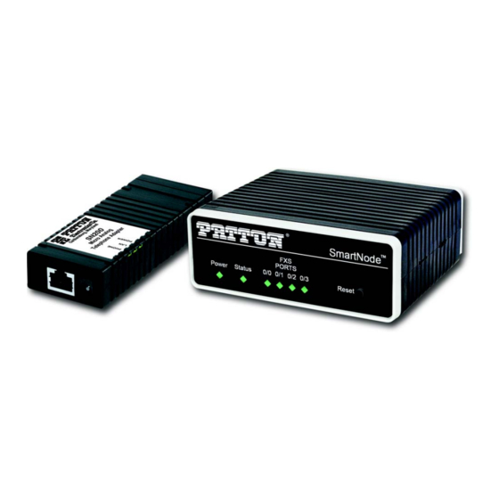
SmartNode
Analog Telephone Adapter and
VoIP Gateway
User Manual
This is a Class B device and is not intended for use in a residential environment.
REGULATORY MODEL NUMBER: 13269D4-001
SN200
™
Sales Office:
+1 (301) 975-1000
Technical Support:
+1 (301) 975-1007
E-mail:
support@patton.com
WWW:
www.patton.com
Part Number: 07MSN200-UM, Rev. C
Revised: October 9, 2020
Advertisement
Table of Contents

Related Manuals for Patton SmartNode SN200


Summary of Contents for Patton SmartNode SN200
- Page 1 This is a Class B device and is not intended for use in a residential environment. REGULATORY MODEL NUMBER: 13269D4-001 Sales Office: +1 (301) 975-1000 Technical Support: +1 (301) 975-1007 E-mail: support@patton.com WWW: www.patton.com Part Number: 07MSN200-UM, Rev. C Revised: October 9, 2020...
- Page 2 Under no condition shall Patton Electronics be liable for any damages incurred by the use of this product. These damages include, but are not limited to, the following: lost profits, lost savings and incidental or consequential damages arising from the use of or inability to use this product.
-
Page 3: Table Of Contents
SN200 Series Quick Start..........................13 General information............................15 Applications overview............................21 SmartNode Installation ........................... 24 Initial Configuration ............................30 Contacting Patton for Assistance........................35 Compliance Information ..........................38 Specifications ..............................40 Cabling ................................44 Port pin-outs ..............................48 SmartNode Device Factory Configuration ....................... -
Page 4: Table Of Contents
Table of Contents Summary Table of Contents ..........................3 Table of Contents ............................4 List of Figures ..............................7 List of Tables ..............................8 About this guide ............................... 9 Audience................................9 Structure................................9 Precautions ..............................9 Safety when working with electricity ......................Deutsch .............................. - Page 5 ........................... 34 Contacting Patton for Assistance........................35 Introduction ..............................36 Contact information ............................36 Contacting Patton Technical Services for Free Support ................36 Warranty Service and Returned Merchandise Authorizations (RMAs) ............... 36 Warranty coverage ............................ 36 Out-of-warranty service ........................37 Returns for credit ..........................
- Page 6 SmartNode 200 User Manual Ethernet ................................ 49 port................................. 49 FXO port ............................... 50 SmartNode Device Factory Configuration ....................... 51 Introduction ..............................52 Reset Button Functions ..........................53 Introduction ..............................54 Resetting the SmartNode device when it is operating and the Power LED is lit ..........
-
Page 7: List Of Figures
List of Figures SmartNode 200 ............... . 16 SN200 rear panels . -
Page 8: List Of Tables
List of Tables Rear panel ports and LED Definitions ............18 SN200 LED and Button Definitions . -
Page 9: About This Guide
5, starting on page 30, leads you through the steps to set up a new SmartNode device and down- • load a configuration Chapter 6, starting on page 35, contains information on contacting Patton technical support for assistance • Appendix A, starting on page 38, provides compliance info for the SmartNode device •... -
Page 10: Safety When Working With Electricity
CAUTION Safety when working with electricity The SmartNode device contains no user serviceable parts, and is not be opened by the user. The equipment shall be returned to Patton Electronics for repairs or repaired by qualified service personnel. WARNING Mains Voltage: In systems without a power switch, line voltages are present in the power supply when the power cord is connected. -
Page 11: Deutsch
SmartNode 200 User Manual Hazardous network voltages are present in WAN ports regardless of whether power to the SmartNode is ON or OFF. To avoid electric shock, use caution when near WAN ports. When detaching the cables, detach the end away from the Smart- WARNING Node first. -
Page 12: General Observations
SmartNode 200 User Manual In Übereinstimmung mit den Anforderungen der Richtlinie 2002/96/EG über Elektro- und Elektronik-Altgeräte (WEEE) muss sichergestellt sein, dass Altgeräte von anderem Abfall und Schrott getrennt werden und dem Sammel- und Verwertungssystem für Elektro- und Elektronik-Altgeräte in Ihrem Land zum Recycling zugeführt werden. General observations Do not stack multiple SmartNode devices directly on top of one another, and do not place items on top of the device. -
Page 13: Sn200 Series Quick Start
Chapter 1 SN200 Series Quick Start Chapter contents Default IP Settings ..............................14 Default Login ................................14 Analog Port Pinout..............................14... -
Page 14: Default Ip Settings
You are responsible for creating a new administrator account to maintain system secu- rity. Patton Electronics accepts no responsibility for losses or damage caused by loss or misuse of passwords. Refer to Chapter 4 “Accessing the CLI” , section “Selecting a secure IMPORTANT password”... -
Page 15: General Information
Chapter 2 General information Chapter contents SmartNode 200 overview ............................16 SN200 rear panel port and LEDs definitions ....................17 SN200 front panel LED and button definitions ....................19... -
Page 16: Smartnode 200 Overview
• ACL (access control list) • Secure Zero Touch Provisioning • • Optionally, the product supports (at additional cost): SIP-TLS/SRTP • For the up-to-date listing of available models, refer to the SmartNode VoIP Note page at https://www.patton.com/products/voip-comparison.asp. SmartNode 200 overview... -
Page 17: Sn200 Rear Panel Port And Leds Definitions
SmartNode 200 User Manual 2 • General information SN200 rear panel port and LEDs definitions Depending on the model, SN200 ATAs have 1, 2, or 4 analog FXS ports (see figure Figure 2. SN200 rear panels SmartNode 200 overview... -
Page 18: Rear Panel Ports And Led Definitions
SmartNode 200 User Manual 2 • General information SN200 rear panel ports and LEDs are described in table Table 1. Rear panel ports and LED Definitions Port/LED Description Ethernet port RJ-45 connector that connects the SmartNode device to ETH 0/0 an Ethernet device (e.g., a cable or DSL modem, or LAN (The SN200/1JS1V/EUI Ethernet port is not switch). -
Page 19: Sn200 Front Panel Led And Button Definitions
SmartNode 200 User Manual 2 • General information Figure 3. SN200 front panels SN200 front panel LED and button definitions figure 3 shows SN200 LEDs and the Reset button; the definitions are listed in table 2. If an error occurs, all LEDs will flash for more than 5 seconds until the device Note reboots. - Page 20 SmartNode 200 User Manual 2 • General information Table 2. SN200 LED and Button Definitions (Continued) LED/Button Description Status LED Blinks during bootup phase and goes solid-green afterwards. (SN200/2JS2V/EUI and SN200/4JS4V/ The LED also blinks (faster) during provisioning and firmware EUI only) update.
-
Page 21: Applications Overview
Chapter 3 Applications overview Chapter contents Introduction ................................22 Applications ................................22... -
Page 22: Introduction
3 • Applications overview Introduction Patton’s SmartNode 200 ATAs and VoIP Gateways deliver the features you need for advanced voice applica- tions. They combine high quality voice-over-IP with powerful quality of service, provisioning and monitoring functions to build professional, secure and reliable VoIP network services. This chapter describes typical appli- cations for which this SmartNode is uniquely suited. - Page 23 SmartNode 200 User Manual 3 • Applications overview Figure 5. 4-Port SN200 ATA application Figure 6. 1 FXS/1 FXO SN200 ATA application Applications...
-
Page 24: Smartnode Installation
Chapter 4 SmartNode Installation Chapter contents Planning the Installation............................25 Site log ................................25 Network information ............................25 Network diagram ............................25 IP related information .............................25 Software tools ..............................26 Power source ..............................26 Installing the SmartNode device ..........................26 Placing the SmartNode device .........................26 Connecting cables ............................27 Connecting analog interface cable or cables ....................27... -
Page 25: Planning The Installation
26 to install the device. Site log Patton recommends that you maintain a site log to record all actions relevant to the system, if you do not already keep such a log. Site log entries should include information such as listed in table Table 3. -
Page 26: Software Tools
If you suspect that your AC power is not reliable, for example if room lights flicker often or there is machinery with large motors nearby, have a qualified professional test the power. Patton recommends that you include an uninterruptible power supply (UPS) in the installation to ensure that VoIP service is not impaired if the power fails. -
Page 27: Connecting Cables
SmartNode 200 User Manual 4 • SmartNode Installation Connecting cables Do not work on the system or connect or disconnect cables during periods of lightning activity. WARNING The interconnecting cables shall be acceptable for external use and shall be rated for the proper application with respect to voltage, current, anticipated temperature, flam- WARNING mability, and mechanical serviceability. -
Page 28: Connecting The 10/100Base-T Ethernet Lan Cable
1. Verify that the AC power supply included with your device is compatible with local standards. If it is not, refer to Chapter 6, “Contacting Patton for Assistance” on page 35 to find out how to replace it with a com- patible power supply. - Page 29 SmartNode 200 User Manual 4 • SmartNode Installation 4. Verify that the Power LED (see figure 3 on page 19) is lit. Once the Status LED becomes solid the Smart- Node device is ready. Congratulations, you have finished installing the SmartNode device! Now go to Chapter 5, “Initial Configura- tion”...
-
Page 30: Initial Configuration
Chapter 5 Initial Configuration Chapter contents Introduction ................................31 Connecting the SN200 to a laptop PC ........................31 Configure the Desired IP Address ........................32 Factory-default IP Settings ........................32 Login ................................32 Changing the WAN IP address .........................33 Loading the Configuration (optional)........................33 Additional Information ............................34... -
Page 31: Introduction
SmartNode 200 User Manual 5 • Initial Configuration Introduction This chapter leads you through the basic steps to set up a new SmartNode device and to download a configura- tion. If you haven’t already installed the SmartNode device, refer to Chapter 4, Note "SmartNode Installation"... -
Page 32: Configure The Desired Ip Address
SmartNode 200 User Manual 5 • Initial Configuration Figure 10. Connecting SmartNode device and PC to a LAN with DHCP server. You can check the connection to the SmartNode by executing the ping command from the PC command win- dow as follows: ping 192.168.200.10 Configure the Desired IP Address Factory-default IP Settings... -
Page 33: Changing The Wan Ip Address
Loading the Configuration (optional) WebWizard Community provides a collection of Wizards that help to reduce the setup time of a Patton device. Simply download the appropriate Wizard to your device, execute it locally, and you are ready to do phone calls after the SmartNode has rebooted. -
Page 34: Additional Information
In addition to that the Knowledgebase provides configuration file templates that may fit your application. If your application is unique and not covered by any of Patton’s configura- Note tion templates, you can manually configure the SmartNode instead of load- ing a configuration file template. -
Page 35: Contacting Patton For Assistance
Chapter 6 Contacting Patton for Assistance Chapter contents Introduction ................................36 Contact information..............................36 Contacting Patton Technical Services for Free Support ...................36 Warranty Service and Returned Merchandise Authorizations (RMAs)..............36 Warranty coverage ............................36 Out-of-warranty service ..........................37 Returns for credit ............................37 Return for credit policy ..........................37... -
Page 36: Introduction
(RMA). Contact information Patton Electronics offers a wide array of free technical services. If you have questions about any of our other products we recommend you begin your search for answers by using our technical knowledge base. Here, we have gathered together many of the more commonly asked questions and compiled them into a searchable database to help you quickly solve your problems. -
Page 37: Out-Of-Warranty Service
RMA#: xxxx 7622 Rickenbacker Dr. Gaithersburg, MD 20879-4773 USA Patton will ship the equipment back to you in the same manner you ship it to us. Patton will pay the return shipping costs. Warranty Service and Returned Merchandise Authorizations (RMAs) -
Page 38: A Compliance Information
Appendix A Compliance Information Chapter contents Compliance ................................39 ................................39 Safety ................................39 Radio and TV Interference (FCC Part 15) ......................39 EC Declaration of Conformity ..........................39 Authorized European Representative ........................39... -
Page 39: Compliance
SmartNode 200 User Manual A • Compliance Information Compliance FCC Part 15, Class B • EN55032, Class B • EN55024 • Safety UL 62368-1/CSA C22.2 N0. 62368-1 • • IEC/62368-1 AS/NZS 62368-1 • Radio and TV Interference (FCC Part 15) This equipment generates and uses radio frequency energy, and if not installed and used properly—that is, in strict accordance with the manufacturer's instructions—may cause interference to radio and television recep- tion. -
Page 40: B Specifications
Appendix B Specifications Chapter contents Voice Connectivity ..............................41 Data Connectivity ..............................41 Voice Processing (signaling dependent) .........................41 Fax support ................................42 Voice Signaling..............................42 Voice Routing—session router ..........................42 IP Services ................................42 Management .................................43 System ...................................43 Physical .................................43... -
Page 41: Voice Connectivity
SmartNode 200 User Manual B • Specifications Refer to the software feature matrix for the most up-to-date specifications. Note Voice Connectivity 1, 2 or 4 FXS ports, RJ-11/12 1 FXS port and 1 FXO port, RJ-11/12 2-wire Loopstart EuroPOTS (ETSI EG201188) Programmable AC impedance, feeding, ring and onhook voltage Caller-ID FSK and ITU V.23/Bell 202 generation 5 REN load on FXS port... -
Page 42: Fax Support
SmartNode 200 User Manual B • Specifications Fax support Automatic fax detection mechanism T.38 Fax-Relay (Gr. 3 Fax, 9.6 k, 14.4 K) G.711 Fax-Bypass Voice Signaling SIPv2 SIPv2 over IPv6 SIPv2 over TLS - (licensed feature - separate purchase) SIP call transfer, redirect Overlap or en-bloc dialing DTMF in-band, out-of-band Voice Routing—session router... -
Page 43: Management
DHCP client and server (IPv4 and IPv6—Dual Stack) DNS client and relay-server, DynDNS Management Patton Cloud Management Web-based GUI; Trinity WEB Wizard Industry standard CLI with remote Telnet and SSH access, fully documented HTTP and HTTPs web management and firmware loading... -
Page 44: C Cabling
Appendix C Cabling Chapter contents Introduction ................................45 Ethernet ................................45 Analog FXS ................................46 Analog FXO ................................47... -
Page 45: Introduction
SmartNode 200 User Manual C • Cabling Introduction This section provides information on the cables used to connect the SmartNode device to the existing network infrastructure and to third party products. Ethernet Ethernet devices (10/100Base-T) are connected to the SmartNode over a cable with an RJ-45 plug. The Ether- net port on the SmartNode device is Auto-MDX. -
Page 46: Analog Fxs
SmartNode 200 User Manual C • Cabling Analog FXS The Interconnecting cables shall be acceptable for external use and shall be rated for the proper application with respect to volt- age, current, anticipated temperature, flammability, and CAUTION mechanical serviceability. The FXS ports are connected to analog terminals (phones, fax machines, answering machines, etc.) via cables terminated with RJ-11 connectors (see section “FXS port”... -
Page 47: Analog Fxo
SmartNode 200 User Manual C • Cabling Analog FXO The Interconnecting cable shall be acceptable for external use and shall be rated for the proper application with respect to volt- age, current, anticipated temperature, flammability, and CAUTION mechanical serviceability. Applicable to a SmartNode equipped with an FXO port. The FXO port is connected to an analog phone line via a cable terminated with an RJ-11 connector (see section “FXO port”... -
Page 48: D Port Pin-Outs
Appendix D Port pin-outs Chapter contents Introduction ................................49 Ethernet ................................49 port................................49 FXO port ................................50... -
Page 49: D Port Pin-Outs
SmartNode 200 User Manual D • Port pin-outs Introduction This section provides pin-out information for the ports of the SmartNode. Ethernet Table 6. 10/100 Base-T RJ-45 socket Signal Pins not listed are not used. Note FXS port The FXS ports use an RJ-11 connector with 6 positions. The middle two positions 3 and 4 are used according table 7 figure Table 7. -
Page 50: Fxo Port
SmartNode 200 User Manual D • Port pin-outs FXO port The FXO port uses an RJ-11 connector with 6 positions. The middle two positions 3 and 4 are used according table 8 figure Pins not listed are not used. Note Table 8. -
Page 51: E Smartnode Device Factory Configuration
Appendix E SmartNode Device Factory Configuration Chapter contents Introduction ................................52... -
Page 52: Introduction
SmartNode 200 User Manual E • SmartNode Device Factory Configuration Introduction Factory configuration settings for the SmartNode device can be obtained with the following command through the CLI; login: admin password: <Enter> 192.168.200.10>show config:shipping-config See Chapter 5, "Initial Configuration" on page 30 for more details about IP address settings for initial configu- ration. -
Page 53: F Reset Button Functions
Appendix F Reset Button Functions Chapter contents Introduction ................................54 Resetting the SmartNode device when it is operating and the Power LED is lit .............55 Very exceptional case—minimal config recovery ....................56... -
Page 54: Introduction
SmartNode 200 User Manual F • Reset Button Functions Introduction The Reset button (see figure 16) is used to do the following: Reboot the SmartNode device (see section “Resetting the SmartNode device when it is operating and the • Power LED is lit” on page 55) •... -
Page 55: Resetting The Smartnode Device When It Is Operating And The Power Led Is Lit
Figure 17. Reset button periods (in seconds) for performing actions Table 9. Results from pressing the Reset button Period Action Reboot device (less than 1 second) Patton Cloud On-boarding procedure. Do the following: (press twice with Log into Patton Cloud at https://patton.io. 1-second gap between presses) Click on Devices. -
Page 56: Very Exceptional Case-Minimal Config Recovery
55, the SmartNode device is still not operational, the following may remedy the problem by erasing the entire contents of flash memory (no exceptions). However it is recommended that in such a case the device be sent to Patton for analysis and repair. See section “Warranty Service and Returned Merchandise Authorizations (RMAs)”... - Page 57 SmartNode 200 User Manual F • Reset Button Functions 5. Once booted up, the device will run using the “minimal-config”: #----------------------------------------------------------------# # # # Minimal configuration file # # # #----------------------------------------------------------------# cli version 4.00 telnet-server shutdown ssh-server ...
-
Page 58: G End User License Agreement
Appendix G End User License Agreement Chapter contents End User License Agreement ..........................59 1. Definitions ..............................59 2. Title ................................59 3. Term ................................59 4. Grant of License ............................59 5. Warranty ..............................60 6. Termination ..............................60 7. Notices ...............................60 8. Other Licenses ............................60 9. -
Page 59: End User License Agreement
End User agrees to the following conditions: 1. Definitions “Effective Date” shall mean the earliest date of purchase or download of a product containing the Patton Electronics Company Program(s) or the Program(s) themselves. “Program(s)” shall mean all software, software documentation, source code, object code, or executable code. -
Page 60: Warranty
Program(s), even if Patton Electronics Company has been advised of the possi- bility of such damages. Because some states do not allow the exclusion or limitation of liability for consequen- tial or incidental damages, the above limitation may not apply to you. -
Page 61: Unenforceable Provisions
State of Maryland, USA for any dispute arising under or relating to this agreement and waives user’s right to institute legal proceedings in any other jurisdiction. Patton shall be entitled to institute legal proceedings in connection with any matter arising under this agreement in any juris- diction where User resides, does business, or has assets.
Need help?
Do you have a question about the SmartNode SN200 and is the answer not in the manual?
Questions and answers