Table of Contents
Advertisement
SN-DTA™
Single/Dual-Port ISDN BRI VoIP
Terminal Adapter
User Manual
Important
approved for use in an industrial environment
This device is approved for connection to the public ISDN telecommunication network, over BRI/S0-ISDN interfaces.
This is a Class B device and is intended for use in a light industrial or residential environment. It is not intended nor
—
.
Sales Office:
+1 (301) 975-1000
Technical Support:
+1 (301) 975-1007
E-mail:
support@patton.com
www.patton.com
Part Number: 07MSNDTA-UM , Rev. B
Revised: February 9, 2012
Advertisement
Table of Contents

Subscribe to Our Youtube Channel
Related Manuals for Patton SN-DTA


Summary of Contents for Patton SN-DTA
-
Page 1: User Manual
SN-DTA™ Single/Dual-Port ISDN BRI VoIP Terminal Adapter User Manual Important This is a Class B device and is intended for use in a light industrial or residential environment. It is not intended nor — approved for use in an industrial environment This device is approved for connection to the public ISDN telecommunication network, over BRI/S0-ISDN interfaces. - Page 2 E-mail: support@patton.com Trademark Statement The term SN-DTA is a trademark of Patton Electronics Company. All other trade- marks presented in this document are the property of their respective owners. Copyright © 2012, Patton Electronics Company. All rights reserved. The information in this document is subject to change without notice. Patton Elec- tronics assumes no liability for errors that may appear in this document.
-
Page 3: Summary Table Of Contents
Summary Table of Contents General information ............................14 SN-DTA Applications overview........................19 SN-DTA installation ............................. 21 SN-DTA initial configuration ........................26 Contacting Patton for assistance ........................33 Compliance information ..........................36 Specifications ..............................39 Cabling ................................. 43 Port pin-outs ..............................46 SN-DTA factory configuration ........................ -
Page 4: Table Of Contents
......................23 Installing the SN-DTA ............................24 Placing the SN-DTA ............................24 Installing cables ...............................24 Connecting the SN-DTA to the ISDN terminals ..................24 Connecting the SN-DTA to the IP network .....................24 Connecting the SN-DTA to the power supply ..................25 External S-Bus power supply ........................25... - Page 5 Contacting Patton for assistance ........................33 Introduction ................................34 Contact information..............................34 Patton support headquarters in the USA ......................34 Alternate Patton support for Europe, Middle East, and Africa (EMEA) ............34 Warranty Service and Returned Merchandise Authorizations (RMAs)..............34 Warranty coverage ............................34 Out-of-warranty service ..........................35 Returns for credit ............................35...
- Page 6 SN-DTA User Manual Introduction ................................44 Ethernet ................................44 ISDN BRI ................................45 Port pin-outs ..............................46 Ethernet ................................47 ISDN BRI NT (Net) port .............................47 ISDN BRI TE (User) port.............................47 SN-DTA factory configuration ........................48 Introduction ................................49 End user license agreement ........................... 50 End User License Agreement ..........................51...
-
Page 7: List Of Figures
SN-DTA application ........ -
Page 8: List Of Tables
SmartNode SN-DTA BRI Ports and Voice Channels ........ -
Page 9: About This Guide
About this guide This guide describes the SN-DTA hardware, installation and basic configuration. For detailed software config- uration information refer to the SmartWare Software Configuration Guide and the available Configuration Notes. Audience This guide is intended for the following users: •... -
Page 10: Precautions
SN-DTA User Manual About this guide Precautions Notes, cautions, and warnings, which have the following meanings, are used throughout this guide to help you become aware of potential problems. Warnings are intended to prevent safety hazards that could result in per- sonal injury. -
Page 11: Safety When Working With Electricity
SN-DTA User Manual About this guide Safety when working with electricity • Do not open the device when the power cord is connected. For systems without a power switch and without an external power adapter, line volt- ages are present within the device when the power cord is connected. -
Page 12: General Observations
SN-DTA User Manual About this guide Always follow ESD prevention procedures when removing and replacing cards. CAUTION Wear an ESD-preventive wrist strap, ensuring that it makes good skin contact. Connect the clip to an unpainted surface of the chassis frame to safely channel unwanted ESD voltages to ground. -
Page 13: Typographical Conventions Used In This Document
Terminal sessions and information the system displays are in screen font. node The leading IP address or nodename of a SN-DTA is substituted with node in boldface italic font. The leading SN on a command line represents the nodename of the SN-DTA... -
Page 14: General Information
Chapter 1 General information Chapter contents SN-DTA overview..............................15 SN-DTA model codes .............................16 SN-DTA/HP model codes ..........................16 SN-DTA rear panel ............................17 SN-DTA front panel ............................18... -
Page 15: Sn-Dta Overview
ISDN phones and PBX equipment. Supporting two or four concurrent voice or fax calls over an IP network, the SN-DTA is a simple and cost-effective way for home and home-office users to connect their ISDN termi- nals to the cost-saving world of Voice-over-IP. -
Page 16: Sn-Dta Model Codes
The high precision SN-DTA/HP models have a Stratum III clock. The Stratum III clock provides a clock source of < 5 ppm. For PBXs that used to rely on PSTN for accurate clock source, the SN-DTA/HP can pro- vide a PSTN-equivalent high precision clock. The popular DECT PBX needs such high precision clocks. -
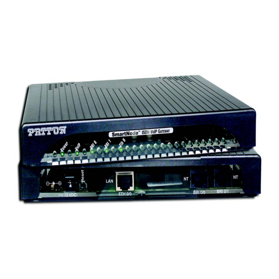
Page 17: Sn-Dta Rear Panel
SN-DTA User Manual 1 • General information SN-DTA rear panel The SN-DTA is an ISDN BRI VoIP Terminal Adapter that supports two VoIP calls via a single ISDN BRI port (see figure 2). The SN-DTA rear panel ports are described in... -
Page 18: Sn-Dta Front Panel
Flashes once per second during boot (startup). VoIP • On indicates that the SN-DTA is registered to an H.323 gatekeeper/SIP server, or, in the case of direct routing, has at least one active VoIP connection. •... -
Page 19: Sn-Dta Applications Overview
Chapter 2 SN-DTA Applications overview Chapter contents Introduction ................................20 Typical application ..............................20... -
Page 20: Introduction
Patton webserver at www.patton.com. Typical application The SmartNode SN-DTA with one or two ISDN BRI ports can be used to make and receive calls to and from Internet Telephony services on any ISDN Terminal (Phone or PBX) (see Figure 4). -
Page 21: Sn-Dta Installation
......................23 Installing the SN-DTA ............................24 Placing the SN-DTA ............................24 Installing cables ...............................24 Connecting the SN-DTA to the ISDN terminals ..................24 Connecting the SN-DTA to the IP network .....................24 Connecting the SN-DTA to the power supply ..................25 External S-Bus power supply... -
Page 22: Planning The Installation
Site log Patton recommends that you maintain a site log to record all actions relevant to the system, if you do not already keep such a log. Site log entries should include information such as listed in table Table 5. -
Page 23: Ip Related Information
Location and mounting requirements The SN-DTA is intended to be placed on a desktop or similar sturdy, flat surface that offers easy access to the cables. Allow sufficient space at the rear of the chassis for cable connections. Additionally, you should consider the need to access the unit for future upgrades and maintenance. -
Page 24: Installing The Sn-Dta
17). Install the connections as follows: 1. BRI NT: Connect the BRI NT port of the SN-DTA to the TE port of the ISDN terminal (phone, PBX or residential S-bus). 2. BRI TE (SN-DTA/2BIS2V/EUI only): Connect the BRI TE port of the SN-DTA to the NT port of the ISDN device (ISDN NT or PBX NT port). -
Page 25: Connecting The Sn-Dta To The Power Supply
Failure to do so could result in equipment damage. 2. Verify that the AC power cord included with your SN-DTA is compatible with local standards. If it is not, refer to chapter 5, “Contacting Patton for assistance”... -
Page 26: Sn-Dta Initial Configuration
Chapter 4 SN-DTA initial configuration Chapter contents Introduction ................................27 Start the SmartNode Discovery Tool........................27 Access the Web Browser (GUI) Interface.......................28 Configuring your SN-DTA ...........................30 Accessing the Internet .............................30 Configuring the default gateway ........................32... -
Page 27: Introduction
“Configuring your SN-DTA” on page 30) This section describes how to quickly access the configuration interface of a SN-DTA and give an overview of the different elements you can configure. For detailed information on all configuration parameters refer to the SmartWare software configuration guide. -
Page 28: Access The Web Browser (Gui) Interface
SN-DTA. To access the web-browser interface, do the following: 1. In the SmartNode Discovery Tool window, select the line that displays the IP address of your SN-DTA. Figure 1. SmartNode Discovery Tool window with webbrowser selected 2. -
Page 29: Main Gui Elements
• The “Navigation Bar” on the left edge presents you with a menu listing giving access to the various configu- ration and status pages of the SN-DTA. • At the top of the page you see the “Current System Path” which displays the location and element currently presented in the main area. -
Page 30: Configuring Your Sn-Dta
Once you have logged in you can use the browser-based graphical user interface (GUI) to configure and man- age your SN-DTA. The information in this section is intended to introduce the configuration tools and get you started. For more detailed information about configuring your SN-DTA, please refer to the SmartWare Configuration Guide. -
Page 31: Ethernet Configuration Page
Internet connection to get the Internet connectivity parameters (IP address, default gateway) automatically from a DHCP server. Use this option when connecting the SN-DTA to a DSL router, a cable modem, or to a company LAN (with a DHCP server). This is the factory default configuration so no con- figuration is required, only the LAN and WAN Ethernet connections should be made to access the Internet immediately. -
Page 32: Configuring The Default Gateway
SN-DTA User Manual 4 • SN-DTA initial configuration Configuring the default gateway To configure the default gateway on the SN-DTA: 1. In the configuration menu pane, click IP/DNS. Click on the Routes tab. The Configuration screen for Static Routes displays (figure Figure 9. -
Page 33: Contacting Patton For Assistance
Contacting Patton for assistance Chapter contents Introduction ................................34 Contact information..............................34 Patton support headquarters in the USA ......................34 Alternate Patton support for Europe, Middle East, and Africa (EMEA) ............34 Warranty Service and Returned Merchandise Authorizations (RMAs)..............34 Warranty coverage ............................34 Out-of-warranty service ..........................35 Returns for credit ............................35... -
Page 34: Introduction
RAS warranty and obtaining a return merchandise authorization (RMA). Contact information Patton Electronics offers a wide array of free technical services. If you have questions about any of our other products we recommend you begin your search for answers by using our technical knowledge base. Here, we have gathered together many of the more commonly asked questions and compiled them into a searchable database to help you quickly solve your problems. -
Page 35: Out-Of-Warranty Service
RMA#: xxxx 7622 Rickenbacker Dr. Gaithersburg, MD 20879-4773 USA Patton will ship the equipment back to you in the same manner you ship it to us. Patton will pay the return shipping costs. Warranty Service and Returned Merchandise Authorizations (RMAs) -
Page 36: A Compliance Information
Appendix A Compliance information Chapter contents Compliance ................................37 EMC Compliance ............................37 Safety Compliance ............................37 PSTN Compliance ............................37 CE Declaration of Conformity ..........................37 EG-Konformitätserklärung............................38 Authorized European Representative ........................38... -
Page 37: Compliance
• ACMA AS/ACIF S003:2008 CE Declaration of Conformity Patton Electronics, Inc declares that this device is in compliance with the essential requirements and other rel- evant provisions of: 2004/108/EC on the approximation of the laws of the member states relating to electromagnetic compati- bility. -
Page 38: Eg-Konformitätserklärung
Die Sicherheitshinweise in der mitgelieferten Produktdokumenta- tion sind zu beachten. Die Konformität mit der oben erwähnten Richtlinie wird durch das CE-Zeichen auf dem Gerät bestätigt. Die unterzeichnete Konformitätserklärung kann heruntergeladen werden von: www.patton.com/certifications/ Authorized European Representative D R M Green, European Compliance Services Limited. - Page 39 Appendix B Specifications Chapter contents DSP..................................40 Voice connectivity ..............................40 Data connectivity ..............................40 Voice processing (signalling dependent) ........................40 Fax and modem support............................40 Voice signalling ..............................41 Voice routing—session router..........................41 services................................41 Management .................................42 Operating environment ............................42 Operating temperature ............................42 Operating humidity ............................42 System...................................42 Dimensions ................................42 Weight and power dissipation...
-
Page 40: B Specifications
One 2/4 channel DSP Voice connectivity Single/dual ISDN BRI So (NT), 4-wire RJ45 port labeled BRI Single ISDN BRI So (TE), 4-wire RJ45 port labeled BRI (SN-DTA/2BIS2V/EUI model only) Point-to-point, point-to-multipoint configurable BRI port provides ISDN line power to connected terminals... -
Page 41: Voice Signalling
DiffServe/ToS set or queue per header bits 802.1p VLAN tagging IPSEC AH & ESP Modes Manual Key; IKE optional AES/DES/3DES Encryption Note To use the IPSec VPN capabilities including AES/DES/3DES encryption with the SN-DTA, you may need to purchase additional license keys. Voice signalling... -
Page 42: Management
SN-DTA User Manual B • Specifications Management Industry standard CLI with remote Telnet access HTTP web management and firmware loading TFTP configuration & firmware loading SNMP v1 agent (MIB II and private MIB) Built-in diagnostic tools (trace, debug) Operating environment Operating temperature 32–104°F (0–40°C) -
Page 43: Cabling
Appendix C Cabling Chapter contents Introduction ................................44 Ethernet ................................44 ISDN BRI ................................45... -
Page 44: Introduction
SN-DTA User Manual C • Cabling Introduction This section provides information on the cables used to connect the SN-DTA and the interface cards to the existing network infrastructure and to third party products. Ethernet Ethernet devices (10Base-T/100Base-T) are connected to the SN-DTA over a cable with RJ-45 plugs. All Ethernet ports on the SN-DTA are Auto-MDX and use any straight or crossover cable to connect to hubs, switches, PCs or other devices. -
Page 45: Isdn Bri
SN-DTA User Manual C • Cabling ISDN BRI The ISDN port connects to ISDN terminals (phones, PBXs) or an ISDN S-BUS using cables terminated with RJ-45 connectors. Use straight-though cables to connect to the TE port of your phone, PBX, or residential S-BUS. -
Page 46: Port Pin-Outs
Appendix D Port pin-outs Chapter contents Ethernet ................................47 ISDN BRI NT (Net) port .............................47 ISDN BRI TE (User) port.............................47... -
Page 47: Ethernet
SN-DTA User Manual D • Port pin-outs Ethernet Table 7. RJ-45 socket Signal Note Pins not listed are not used. ISDN BRI NT (Net) port The BRI phone port uses an 8-pin RJ-45 connector (the pinout is shown in table Table 8. -
Page 48: Sn-Dta Factory Configuration
Appendix E SN-DTA factory configuration Chapter contents Introduction ................................49... -
Page 49: Introduction
SN-DTA User Manual E • SN-DTA factory configuration Introduction The factory configuration settings for the SN-DTA are shown below. #----------------------------------------------------------------# # Factory configuration file #----------------------------------------------------------------# sntp-client sntp-client server primary 129.132.2.21 port 123 version 4 system ic voice 0 low-bitrate-codec g729... -
Page 50: F End User License Agreement
Appendix F End user license agreement Chapter contents End User License Agreement ..........................51 1. Definitions ..............................51 2. Title ................................51 3. Term ................................51 4. Grant of License ............................51 5. Warranty ..............................51 6. Termination ..............................52 7. Other licenses .............................52... -
Page 51: End User License Agreement
Program(s), even if Patton Electronics Company has been advised of the possibil- ity of such damages. Because some states do not allow the exclusion or limitation of liability for consequential or incidental damages, the above limitation may not apply to you. -
Page 52: Termination
The End User may terminate this agreement by returning the Designated Equipment and destroying all copies of the licensed Program(s). Patton Electronics Company may terminate this Agreement should End User violate any of the provi- sions of section “4. Grant of License”...
Need help?
Do you have a question about the SN-DTA and is the answer not in the manual?
Questions and answers