Table of Contents
Advertisement
Quick Links
Advertisement
Table of Contents

Related Manuals for ConMed SYSTEM 5000


Summary of Contents for ConMed SYSTEM 5000
- Page 1 Operator’s Manual E L E C T R O S U R G I C A L U N I T...
- Page 2 CONMED’s option) the same without charge, provided that routine maintenance as specified in this manual has been performed using replacement parts approved by CONMED. This warranty is void if the product is used in a manner or for purposes other than intended. © 2007 CONMED Corporation 525 French Road Utica, New York 13502 U.S.A.
-
Page 3: Table Of Contents
Table of Contents & List of Illustrations Section Title Page General Information ................. 1-1 Cautions ...................... 1-1 1.1.1 Cautions For Equipment Preparation ................1-2 1.1.2 Cautions For Patient Preparation ..................1-2 1.1.3 Cautions For Use ......................1-4 1.1.4 Cautions For Testing or Servicing ..................1-5 1.1.5 Electromagnetic Compatibility .................. - Page 4 Section Title Page 2.6.3 Monopolar Pulse Coag ....................2-11 2.6.4 Fluids Specialty Mode ..................... 2-11 2.6.5 Lap Specialty Mode ......................2-11 2.6.6 Programming ........................2-11 2.6.6.1 Storing Programs ......................2-11 2.6.6.2 Using Programs ......................2-11 2.6.7 Remote Power Control ....................2-11 2.6.7.1 Changing Monopolar Power Remotely ................
-
Page 5: General Information
• ReadiPlug™ universal accessory receptacle The System 5000™ provides a broad range eliminates the need for foot-controlled adapt- of capabilities in a single, general-purpose ers. electrosurgical generator. This rugged ESU fulfills •... -
Page 6: Cautions For Equipment Preparation
Safe and effective electrosurgery is dependent not 60-8030-001) allows two System 2500™ or only on equipment design, but also on factors System 5000™ units to be stacked in a safe under the control of the operator. It is important manner. - Page 7 • The System 5000™ mobile pedestal is made of rax. nonconductive plastic, that can hold a static charge. It should not be used in a flammable •...
-
Page 8: Cautions For Use
FDA. For further informa- dry gauze. tion, please contact the Regulatory Affairs • The use of electrosurgery on patients with Department of CONMED Electrosurgery at cardiac pacemakers, AICDs, neurostimulators 800-552-0138, 303-699-7600 or FAX 303- or other active implants is potentially hazard- 699-9854. -
Page 9: Cautions For Testing Or Servicing
Cautions For Testing or Servicing • Confirm the desired bipolar mode is selected • Service should not be attempted without refer- prior to use to ensure output characteristics ence to the System 5000™ service manual are suitable for the intended procedure. (Catalog Number 60-8017-ENG). -
Page 10: Electromagnetic Compatibility
Guidance and Manufacturer’s Declaration – Electromagnetic Emissions The System 5000™ Electrosurgical Unit is intended for use in the electromagnetic environment specified below. The customer or the end user of the System 5000 Electrosurgical Unit should assure that it is used in such an environment. Emissions test... -
Page 11: Iec 60601-1-2 Table 202
Guidance and Manufacturer’s Declaration – Electromagnetic Immunity The System 5000™ Electrosurgical Unit is intended for use in the electromagnetic environment specified below. The customer or the end user of the System 5000 Electrosurgical Unit should assure that it is used in such an environment. Immunity Test... -
Page 12: Iec 60601-1-2 Table 204
Guidance and Manufacturer’s Declaration – Electromagnetic Immunity The System 5000™ Electrosurgical Unit is intended for use in the electromagnetic environment specified below. The customer or the end user of the System 5000 Electrosurgical Unit should assure that it is used in such an environment. Immunity Test... -
Page 13: Iec 60601-1-2 Table 206
The System 5000™ Electrosurgical Unit is intended for use in an electromagnetic environment in which radiated RF disturbances are controlled. The customer or the user of the System 5000™ Electrosurgical Unit can help prevent elec- tromagnetic interference by maintaining a minimum distance between portable and mobile RF communications equip- ment (transmitters) and the System 5000™... -
Page 14: Regulatory Compliance
1.2.3 Regulatory Compliance Designed to comply with Medical Electrical Equipment Standards (UL2601-1: 2000, IEC60601-1: 1995, IEC60601-1-1: 2000, IEC60601-1-2: 2001, IEC60601-1-4: 2000, IEC60601-2-2: 1998, ANSI/AAMI HF18: 2001). Manufactured in an ISO 13485: 2003 Registered Facility. Type of protection against electric shock: IEC Class 1. Degree of protection against electric shock: Type CF, Defibrillator Proof. -
Page 15: Other Specifications
1.2.10 Other Specifications Power Cord: All units supplied with an IEC-320 250V 10A 65°C mains inlet connector. Power cords can be ordered from CONMED Electrosurgery or obtained from other sources if the following specifications are met: Region Specification Description Standard... -
Page 16: Explanation Of Symbols
Press to enable or disable Remote 1.3.1 Control Panel Power Control. Note: International System 5000™ units use symbols on the Control Panel. Some symbols are Program replaced by words on the domestic (U.S.) units. These words are indicated by bold text in the sym- bol description. -
Page 17: Rear Panel
Power on: connected to the mains. Equipotential Ground Terminal. Power off: disconnected from the mains. Replace fuse only with type and rat- ing as shown. 1.3.4 Rear Panel Enclosure resists entry of vertically Caution - High Voltage Inside - falling water. Refer servicing to qualified person- nel. -
Page 18: Output Characteristic Curves
Output Characteristic Curves Figure 1.1 illustrates output power delivered to rated load for all available modes. Figure 1.2 illustrates the maximum peak voltage available at a given power setting and output mode. Section 1.2 specifies rated loads and maximum power for each mode, while figures 1.3 – 1.11 illustrate output power delivered to a range of load resistances for each mode. -
Page 19: Figure 1.3 Load Regulation, Monopolar Pure Cut
Load Resistance (Ohms) Figure 1.3 Load Regulation, Monopolar Pure Cut Load Resistance (Ohms) Figure 1.4 Load Regulation, Monopolar Blend 1 1-15... - Page 20 Load Resistance (Ohms) Figure 1.5 Load Regulation, Monopolar Blend 2 Load Resistance (Ohms) Figure 1.6 Load Regulation, Monopolar Blend 3 1-16...
-
Page 21: Figure 1.7 Load Regulation, Monopolar Pinpoint Coag
Load Resistance (Ohms) Figure 1.7 Load Regulation, Monopolar Pinpoint Coag Load Resistance (Ohms) Figure 1.8 Load Regulation, Monopolar Standard Coag 1-17... -
Page 22: Figure 1.9 Load Regulation, Monopolar Spray Coag
Load Resistance (Ohms) Figure 1.9 Load Regulation, Monopolar Spray Coag Load Resistance (Ohms) Figure 1.10 Load Regulation, Bipolar Micro 1-18... -
Page 23: Figure 1.11 Load Regulation, Bipolar Macro
Load Resistance (Ohms) Figure 1.11 Load Regulation, Bipolar Macro Load Resistance (Ohms) Figure 1.12 Load Regulation, Lap Spray 1-19... -
Page 24: Figure 1.13 Load Regulation, Lap Standard
Load Resistance (Ohms) Figure 1.13 Load Regulation, Lap Standard 1-20... -
Page 25: Installation And Operation
Biomedical Technician should perform this inspec- g) Connect the power cord to the back of the tion. Notify the carrier and your CONMED rep- ESU. Installation of the ESU may now be resentative immediately if damage is found. completed. - Page 26 This control may be left at any desired • Pressing the Cut Mode Scroll Key until position. Release the bipolar footswitch and confirm the System 5000™ returns to its idle the Pure Cut Activation indicator is illu- state. Set the bipolar power setting to 1 watt minated.
-
Page 27: Preliminary Performance Testing
Prior to activation, the BARGRAPH will 16. Disconnect the single dispersive elec- show a relative measure of the contact qual- trode and confirm that the System 5000™ ity between the two elements of the dual beeps three times and the Single and Dual dispersive electrode. -
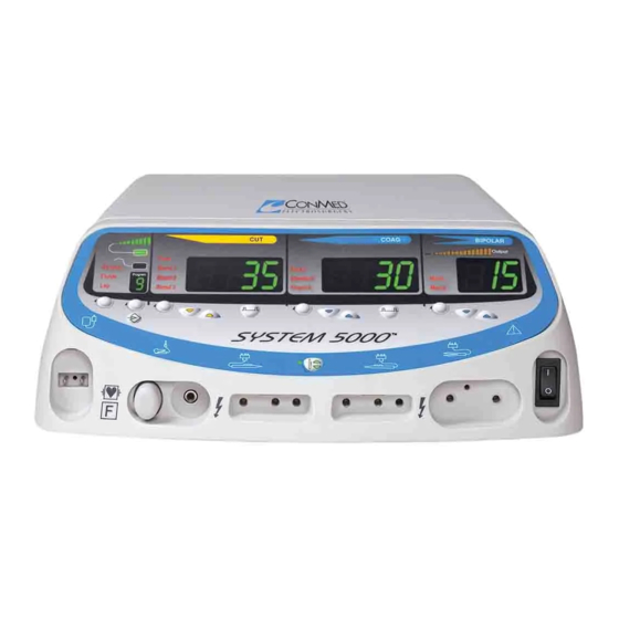
Page 28: Figure 2.1 Control Panel
4. FLUIDS SPECIALTY MODE INDICATOR 5. LAP SPECIALTY MODE INDICATOR 6. PROGRAM INDICATOR 7. SPECIALTY MODE SCROLL KEY SYSTEM 5000 8. PROGRAM SELECT SCROLL KEY 9. PROGRAM STORE KEY 35. BIPOLAR POWER ADJUSTMENT KEYS 17. CUT MODE 34. BIPOLAR SCROLL KEY SCROLL KEY 18. -
Page 29: Output Panel
11. BLEND 1 INDICATOR: Illuminates when 28. PULSE COAG KEY: Pressing this key will select or deselect Pulse Coag. monopolar Blend 1 is selected. 29. MICRO BIPOLAR INDICATOR: 12. BLEND 2 INDICATOR: Illuminates when Illuminates when micro bipolar is selected. monopolar Blend 2 is selected. -
Page 30: Rear Panel
NEVER CONNECT MORE THAN ONE ACCESSORY AT A TIME TO THIS 46. BIPOLAR FOOTSWITCH RECEPTACLE. CONNECTOR: A 3-pin threaded con- nector designed to accept any CONMED 39. HAND-CONTROLLED MONOPOLAR Electrosurgery single-treadle bipolar ACCESSORY RECEPTACLE: Two inde- footswitch. pendent receptacles are provided for the con- nection of hand-controlled monopolar acces- 47. -
Page 31: Set Up For Use
PLACE ACTIVE ACCESSORIES ON THE Contact your CONMED Sales Representative PATIENT. or CONMED Customer Service at the num- 3. Connect the footswitches, as required, to the bers listed on the inside front cover of this rear of the ESU (not required if only hand- manual. - Page 32 c) Illuminating all three activation indica- the dispersive electrode have not been satisfied tors, all eight key indicators, two disper- (see instruction 8). sive electrode indicators and the entire 8. The A.R.M.™ dispersive electrode contact dual dispersive electrode contact quality quality monitor can automatically detect and BARGRAPH.
- Page 33 fewer segments. Acceptable contact quality to 12. Set the Monopolar Cut Mode to Pure for enable safe use of the ESU will be indicated cutting or one of three Blend modes for by illumination of one or more segments. All desired cutting with hemostasis.
-
Page 34: Operation
- To increment or decrement the power The surgical effects obtained are dependent on a setting one step, momentarily press and number of factors including waveform, electrode release the desired CUT, COAG, or size, electrode geometry, power level and surgical BIPOLAR Power Adjustment Key. -
Page 35: Monopolar Pulse Coag
RESULT IN PATIENT INJURY. LISTEN The unit automatically stores the most recent set- FOR THE DISTINCT PULSE CUT tings when powering down and will restore those ACTIVATION TONE DURING ACTIVA- settings when the unit is turned ON. An “L ” (for TION TO CONFIRM PULSE CUT IS Last) will be displayed in the Program Location INDEED ACTIVE. -
Page 36: Changing Monopolar Power Remotely
COAG button to adjust the coagulation 2.7.3 Periodic Inspection power. The System 5000™ should be visually inspected 3. An acceptance tone will sound, allowing at least every year. This inspection should include power adjustments only from the accessory checks for: where the double click was detected. -
Page 37: Dual Dispersive Electrode Alarm
• Aluminum enclosure and heatsinks. 2.8.4 If All Else Fails • The ESU rear handle is aluminum. Contact CONMED Electrosurgery Technical • Thermoset printed wiring boards containing Services at the phone or fax numbers listed on miscellaneous electronic components. the inside front cover of this manual. Please have the model and serial numbers from the rear panel •... -
Page 38: Figure 2.4 Accessory Schematics
MONOPOLAR HANDSWITCHED ACTIVE CONNECTIONS HANDSWITCH (OPTIONAL) BIPOLAR ACTIVE CONNECTIONS COAG SINGLE FOIL ELECTRODE DUAL FOIL ELECTRODE SINGLE FOIL ELECTRODE DUAL FOIL ELECTRODE NEUTRAL ELECTRODE CONNECTIONS NEUTRAL ELECTRODE CONNECTIONS MONOPOLAR FOOTSWITCH CONNECTIONS COAG COAG BIPOLAR FOOTSWITCH CONNECTIONS MONOPOLAR HANDSWITCHED ACTIVE CONNECTIONS MONOPOLAR HANDSWITCHED ACTIVE CONNECTIONS HANDSWITCH (OPTIONAL) HANDSWITCH (OPTIONAL)
Need help?
Do you have a question about the SYSTEM 5000 and is the answer not in the manual?
Questions and answers