Sign In
Upload
Download
Table of Contents
Contents
Add to my manuals
Delete from my manuals
Share
URL of this page:
HTML Link:
Bookmark this page
Add
Manual will be automatically added to "My Manuals"
Print this page
×
Bookmark added
×
Added to my manuals
Manuals
Brands
ConMed Manuals
Medical Equipment
Advantage
Instruction manual
ConMed Advantage Instruction Manual
Hide thumbs
1
2
Table Of Contents
3
4
5
6
7
8
9
10
11
12
13
14
15
16
17
18
19
20
21
22
23
24
25
26
27
28
29
30
31
32
33
34
35
36
37
38
39
40
41
42
43
44
45
46
47
48
49
50
51
52
53
54
55
56
57
58
59
60
61
62
63
64
65
66
67
68
69
70
71
72
73
74
75
76
77
78
79
80
81
82
83
84
85
86
87
88
89
90
91
92
93
94
95
96
97
98
99
100
101
102
103
104
105
106
107
108
109
110
111
112
113
114
115
116
117
118
119
120
121
122
123
124
125
126
127
128
129
130
131
132
133
134
135
136
137
138
139
140
141
142
143
144
145
146
147
148
149
150
151
152
153
154
155
156
157
158
159
160
161
162
163
164
165
166
page
of
166
Go
/
166
Contents
Table of Contents
Troubleshooting
Bookmarks
Table of Contents
Table of Contents
Introduction
Intended Use
Contraindications
Warnings and Precautions
Warnings
Precautions
Symbol Definitions
Environmental Directives
System Indicators
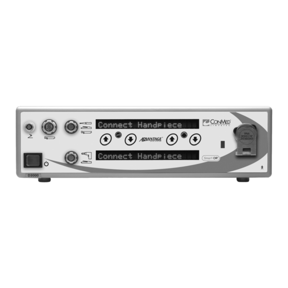
Advantage Controller Front Panel (Top Portion)
Advantage Controller Front Panel (Bottom Portion)
Advantage Controller Back Panel
E9000 Controller Front Panel
E9000 Controller Back Panel
Powerpro Controller Front Panel
Powerpro Controller Back Panel
Handpieces
Group 1 Handpieces
Group 2 Handpieces
Group 3 Handpieces
Group 4 Handpieces
Footswitches
Footswitch, 2-Pedal (5020-053)
Footswitch, 3-Pedal (C9863)
Tubing Sets
Installation and Setup
Handpiece Cord Installation
Footswitch and Handpiece to Controller Installation
Controller Options/Function Switches and Settings
Tubing Set Cassette Installation
Controller Operation
Powerpro Console Irrigation
Footswitch Operation (Advantage Top Portion Only, Powerpro and E9000)
Handpiece Operation
High Speed Shaver (E9005) Operation
Coolflex High Speed Drill (E9010) Operation
Preoperative Functional Test for the Coolflex High Speed Drill
Bur Guard Attachment
Neuro Guard Attachment
Tubing Set Line Attachment
Handpiece Adjustment
Cranial Perforator Drive (E9015) Operation
Microchoice Drills
Tubing Set Attachment (E9418) for Microchoice Handpieces
Preoperative Functional Test for the Microchoice Elite High Speed Drill
Elite High Speed (5020-025) and Medium Speed Drill (5020-021) Attachments and Accessories
Low Speed Drill (5020-026) Operation
Microchoice Saws
Reciprocating Saw (5020-023) Operation
Sagittal Saw (5022-022) Operation
Oscillating Saw (5020-024) Operation
Leverless Handpiece Operation
Microchoice Modular Handpiece (5020-027), Attachments and Accessories
Connecting/Removing Attachments
Pin and Wiredriver Attachments
Universal Drill Attachment
All Jacobs Chuck Attachments
Group 2 Handpiece Cord Button Operation
Preoperative Functional Test for Group 3 Shaver Handpieces
Accessory Insertion and Removal
Advantage Basic (D9820/D9920) and 2-Button (D9824/D9924) Shaver
Handpieces
Small Shaver Handpieces (MC9840, C9840)
Group 3 Handpiece Operation
Activating the Handpiece
Changing Handpiece Speeds
Changing Handpiece Operating Directions
Mini-Driver Handpiece, Attachments and Accessories
3.10.1 Attachments and Accessories
Connecting/Removing Attachments
3.10.3 Pin and Wiredriver Attachments
Sagittal Saw Attachment (K220)
All Jacobs Chuck Attachments
Trinkle Chuck Attachment (K112)
Hudson Chuck Attachment (K113)
ASIF/AO Twist Drill Chuck Attachment (K114A)
3.11 Handpiece Default Settings
Maintenance
Cleaning and Sterilizing
Cleaning Precautions
Controller and Footswitch Cleaning Instructions
Handpiece Cleaning Instructions
Attachment Lubricating Instructions
Sterilization Information
Troubleshooting
Calibration
Fuse Replacement and Voltage Selection Means
Bur Guard Testing Procedure
Ground Continuity Test
Leakage Test
Technical Specifications
Theory of Operation
Controller
Advantage Controller
E9000 Controller
Powerpro Controller
Power Cord Requirements
System Environmental Requirements
Footswitches (5020-053 and C9863)
Handpiece Cords
Tubing Sets
Handpieces
Accessories
Handpieces, Attachments and Accessories
Advertisement
Quick Links
1
Group 1 Handpieces
2
Maintenance
3
Troubleshooting
Download this manual
The
Advantage
Systems Instruction Manual
,
E9000
®
®
and
PowerPro
®
A
CONTROLLER
OPERATION
®
B
E9000
HANDPIECES
®
C
MICROCHOICE
HANDPIECES
D
SHAVER
HANDPIECES
E
MINI-DRIVER™
HANDPIECES
F
MAINTENANCE
G
TECHNICAL
SPECIFICATIONS
Table of
Contents
Previous
Page
Next
Page
1
2
3
4
5
Advertisement
Table of Contents
Need help?
Do you have a question about the Advantage and is the answer not in the manual?
Ask a question
Questions and answers
Related Manuals for ConMed Advantage
Medical Equipment ConMed AER DEFENSE Operator's Manual
Smoke evacuator (24 pages)
Medical Equipment ConMed ABC 130342 Manual
Probes single patient use (10 pages)
Medical Equipment ConMed ABC 133023 Quick Start Manual
Flex probes (6 pages)
Medical Equipment ConMed Linvatec Advantage Turbo D9920 Manual
Shaver handpiece (22 pages)
Medical Equipment ConMed Linvatec Advantage Turbo D9924 Manual
Shaver handpiece (22 pages)
Medical Equipment ConMed SYSTEM 5000 Service Manual
(50 pages)
Medical Equipment ConMed Hyfrecator 2000 Service Manual
Electrosurgical unit (72 pages)
Medical Equipment ConMed sabre 180 Service Manual
Electrosurgical unit (72 pages)
Medical Equipment ConMed Sabre Genesis Service Manual
Electrosurgical generator (20 pages)
Medical Equipment ConMed 24k Quick Setup Manual
(4 pages)
Medical Equipment ConMed SYSTEM 5000 Operator's Manual
Electrosurgical unit (38 pages)
Medical Equipment ConMed PlumeSafe X5 Operator's Manual
Smoke management system (41 pages)
Medical Equipment ConMed PowerPro PRO3520 Instructions For Use Manual
(60 pages)
Medical Equipment ConMed Hall 50 PRO7100B Instruction Manual
Battery handpieces (46 pages)
Medical Equipment ConMed HD4000 Instructions For Use Manual
Autoclavable high definition endoscopes (44 pages)
Medical Equipment ConMed Sabre 2400 Operators & Service Manual
Electrosurgical unit (78 pages)
This manual is also suitable for:
E9000
Powerpro
Table of Contents
Save PDF
Print
Rename the bookmark
Delete bookmark?
Delete from my manuals?
Login
Sign In
OR
Sign in with Facebook
Sign in with Google
Upload manual
Upload from disk
Upload from URL


Need help?
Do you have a question about the Advantage and is the answer not in the manual?
Questions and answers