Table of Contents
Advertisement
Advertisement
Table of Contents

Related Manuals for ConMed Sabre Genesis


Summary of Contents for ConMed Sabre Genesis
- Page 1 Service Manual lEctrosurgical EnErator...
- Page 2 CONMED’s option) the same without charge, provided that routine maintenance as specified in this manual has been performed using replacement parts approved by CONMED. This warranty is void if the product is used in a manner or for purposes other than intended. STERILE EO ©...
-
Page 3: Table Of Contents
Table of Contents & List of Illustrations Section Title Page General Information ....Refer to Operator’s Manual (60-8201) Specifications ......Refer to Operator’s Manual (60-8201) Theory of Operation ................. 3-1 Mode Descriptions ..................3-1 3.1.1 Cut Major Modes ......................3-1 3.1.2 Coag Major Modes ...................... - Page 4 Section Title Page DACview ....................4-12 4.10 Troubleshooting ..................4-12 4.10.1 HVPS Troubleshooting Hints ..................4-14 4.11 Parts Ordering Information ..............4-14 4.12 Assembly Breakdown/Parts Access ............4-15 4.12.1 Top Cover Removal & Replacement ................4-15 4.12.2 Bezel Removal & Replacement ..................4-15 4.12.3 Control/Display Board Removal &...
-
Page 5: Theory Of Operation
Theory of Operation Section 3.0 Sabre Genesis™ functions and essential circuit information are provided in this section. This section begins with a description of the key parameters for each mode. This is followed by an overview of how the system functions and some key operational information for the modules within the system. - Page 6 activations from accessories and the circuitry to • To ensure that the correct outputs are acti- perform the Automatic Return Monitor (A.R.M.) vated, the Monitor also independently function to ensure the integrity of the dispersive senses current at each of the outputs, look- electrode connection.
- Page 7 Indicators: Activation & Mode Keyboard Modes / Activation Request Power Displays Activation Relay ACT RLY Connector Serial Interface RS232 Connector AL TONE ACT TONE System Controller A.R.M Patient RF Output Relays VARM RLY DRV Mono RF INH PFC EN HVEN RF Controller RF MP VS RF BP VS...
-
Page 8: Rf Amplifier And Transformer
3.2.1 High Voltage Power Supply (HVPS) (Vbase_PWM). The RFGATE drive pulses provide the basic pulse The HVPS is comprised of a Power Factor pattern that is used to form the electrosurgical Control (PFC) section and a Forward Converter waveform, and have a set pulse-pattern and pulse- (FC) section. -
Page 9: Activation Command Sensing
3.2.4 Activation Command Sensing RFGATE outputs. To reduce the effects on the microprocessor circuits on the Control/ Each of the Hand Controlled Accessory recep- Display Board from RF noise at the output, tacles incorporate inputs that are used to sense VBASE_PWM and RFGATE are both dif- an activation command from the user. -
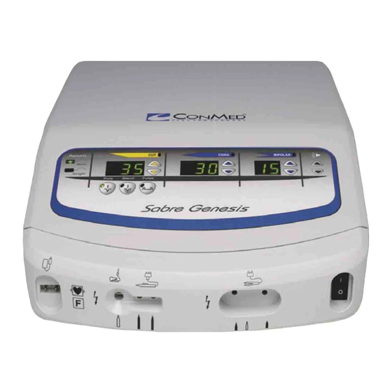
Page 10: Operator Control Panel
Board has the circuit that will reset the system speaker drive current be absent or too low. should the 3.3V supply exceed 3.6V . 3.2.10 Activation Relay Connector 3.2.8 Operator Control Panel There is an Accessory Relay Connector, which • Keyboard: The main operator input device provides a relay closure (SPST switch) that may for choosing operating modes and settings is be used for activating external accessories such as... -
Page 11: Maintenance
This inspection should to protect themselves. Read the safety sum- include checks for the following: mary in Section 1.1.4 of the Sabre Genesis™ Operators Manual before working on the 1) Damage to the power cord and plug. -
Page 12: Output Power
4.5.3 Output Power results. 2) Use test leads to connect the ESU tester to 1) Equipment Requirements: the unit’s return electrode output and the a) Monopolar Footswitch footswitch controlled active output. Set the b) Bipolar Footswitch Load resistance per mode as indicated in c) Commercial ESU Tester (e.g. -
Page 13: Rf Leakage Measurement
4.5.4 RF Leakage Measurement to the patient and operating room staff through unintended paths, which can cause injury. RF NOTE: To ensure accuracy when making leak- leakage occurs because the total energy in the age measurements, perform all leakage testing output voltage waveform is provided with a con- using methods and instruments that are com- ductive path through stray parasitic capacitance... -
Page 14: 4.5.5 Line Frequency Leakage
in Table 4.5 and activate the unit using the corresponding command. Confirm that no meter readings exceed the specified maximum. Table 4.5 Allowable RF Leakage Current - Inactive Monopolar Outputs MEASURED TERMINAL ACTIVATED ACCESSORY MODE RF LEAKAGE (Ma) Combination Monopolar Active Hand Controlled Standard Coag <... -
Page 15: Automatic Return Monitor (A.r.m.) Check
5) Since the Sabre Genesis™ monopolar active see Table 4.8; while that output is activated outputs are disconnected by relays when the in Cut by the appropriate footswitch or hand unit is not activated, active-to-neutral leakage control jumper. Hand control cut activations... -
Page 16: System Calibration
• “nEr” will appear in the Monopolar Cut perform calibration if errors are identified. Power Digital Display, where “n” indicates The Sabre Genesis™ stores its calibration in non- how many major modes require calibration, volatile semiconductor memory, so the calibration... - Page 17 Calibration Set the Calibration System Configuration Dipswitch on the Controller to the ON position Turn main power switch on while pressing both Volume Adjust Keys. Release Volume Adjust Keys when the Monopolar Cut Power Digital Display indicates “ [AL” [AL Lxx Press Tone Loudness Adjustment Down Key [u 500 P Press Monopolar Cut Power Adjustment...
-
Page 18: Calibrating A Monopolar Mode
4.6.3 Calibrating a Monopolar Mode 4.6.4 Calibrating Bipolar Modes This section applies to the Pure Cut, Blend, The Bipolar modes are calibrated using a method Standard Coag. that is very similar to the Monopolar modes. Calibration may be performed by measuring cur- Calibration may be performed by measuring cur- rent or by measuring power. -
Page 19: Completing Calibration
will sound and the resistance in the Monopolar Window will next display “Err”; the Coag Coag Power Digital Display will quit flashing. window will display the error code (a numeric value); and the Bipolar Window will display Now scroll to the other pair of known resistances the storage location of that error code. - Page 20 Table 4.9 DIP Switch Settings Config. Title / Display Default Description for Description for On Switch Element Position TEST / Cut 100’s Run Mode. Activates Test Mode, which inhibits most Required position of the system level monitoring for trouble- for surgery. shooting purposes.
Need help?
Do you have a question about the Sabre Genesis and is the answer not in the manual?
Questions and answers