Table of Contents
Advertisement
Quick Links
Advertisement
Table of Contents
Troubleshooting

Related Manuals for ConMed sabre 180


Summary of Contents for ConMed sabre 180
- Page 1 Service Manual...
-
Page 2: Limited Warranty
CONMED. This warranty is void if the product is used in a manner or for purposes other than intended. U.S. Patent Nos. 4,569,345 - 4,617,927 - 4,848,335 - 4,961,739 and other patents pending. -
Page 3: Table Of Contents
Table of Contents & List of Illustrations Section Title Page GENERAL INFORMATION ........1-1 Precautions . - Page 4 Section Title Page Controller Firmware ..........3-17 3.5.1 RUN Mode .
- Page 5 Figure Title Page Output Power vs. Power Setting ........1-7 Pure Cut Load Regulation .
- Page 6 This page intentionally left blank.
-
Page 7: General Information
•IMPROVED BIPOLAR: Optionally available as a footswitched alternate coagulation mode, the •ISOLATED OUTPUT CIRCUITRY: This fea- Sabre 180 bipolar is designed to start quickly and ture minimizes the probability of alternate ground conclude gracefully with minimal sparking and site burns. Complies with all current internation- tissue sticking. -
Page 8: Precautions
The risk of igniting flammable gases or •The Sabre 180 is equipped to connect two other materials is inherent in electrosurgery and monopolar accessories at one time for the conve- cannot be eliminated by device design. - Page 9 purged and filled with non-flammable gas prior possible from the electrosurgical site and the to abdominal surgery. return electrode. Protective impedances incorpo- rated in the monitoring leads may further reduce •This unit is equipped with the Aspen Return the risk of these burns. Needles should not be Monitor (A.R.M.) which verifies that the return used as monitoring electrodes during electrosurgi- electrode cable is unbroken and connected to the...
-
Page 10: Precautions In Use
•Refer all servicing to qualified personnel. Your Conmed representative will be happy to assist you •If a Dual Foil RETURN Alarm is sounded in getting your equipment serviced. intraoperatively, visually confirm proper return electrode attachment to the patient prior to press- •High voltages are developed within the unit that... -
Page 11: Specifications
•The heat dissipation capability of the heat sink is •Consult the factory for advice before making severely impaired by activating the Sabre 180 in any modifications to the unit. other than its normal operating position. There are no tests requiring operation in any other posi- •Ensure that the RUN-RST-CAL switch is set to... - Page 12 •Independence: Only the activated accessory will be live. Only one accessory may be activated at a time. •Control switch activation resistance: < 1000 ohms. ACCESSORY CONNECTIONS: •CONMED makes available adapters to permit use of accessories with other than standard connectors: •Monopolar Active: 3-pin handswitched and Bovie #12 footswitched. •Monopolar Return: 2-pin A.R.M./REM capable.
-
Page 13: Output Characteristics
1.3 OUTPUT CHARACTERISTICS Figure 1.1 illustrates output power delivered to rated load for all available modes. Section 1.2 specified rated loads and maximum power for each mode, while Figures 1.2-1.6 illustrate output power delivered to a range of load resistances for each mode. SPECIFICATION LIMITS POWER SETTING... -
Page 14: Blend 1 Cut Load Regulation
BLEND 1, 65W BLEND 1, 35W 2000 1000 1500 LOAD RESISTANCE, OHMS FIGURE 1.3 BLEND 1 CUT LOAD REGULATION BLEND 2, 50W BLEND 2, 25W 1000 2000 1500 LOAD RESISTANCE, OHMS FIGURE 1.4 BLEND 2 CUT LOAD REGULATION... -
Page 15: Monopolar Coag Regulation
1000 1500 2000 LOAD RESISTANCE, OHMS FIGURE 1.5 MONOPOLAR COAG REGULATION 1000 LOAD RESISTANCE, OHMS FIGURE 1.6 BIPOLAR COAG REGULATION... -
Page 16: Explanation Of Symbols
1.4 EXPLANATION OF SYMBOLS CONTROL PANEL OUTPUT PANEL HANDSWITCHED OUTPUT - CONNECTION PURE CUT - WAVEFORM WITH MINIMUM FOR HANDSWITCHED MONOPOLAR THERMAL DAMAGE AND HEMOSTASIS ACCESSORIES FOOTSWITCHED OUTPUT - CONNECTION BLEND 1 - CUT WAVEFORM WITH FOR FOOTSWITCHED MONOPOLAR MODERATE HEMOSTASIS ACCESSORIES HIGH VOLTAGE CAUTION - BLEND 2 - CUT WAVEFORM WITH... -
Page 17: Installation And Operation
Conmed representative immediately. Retain orig- inal packing material for future storage or ship- 3. Connect a two-treadle monopolar foot switch ment. - Page 18 7. Control Panel Checks: clockwise. The power should increase from zero to 5 watts. Turn the Coag Power Control coun- a) Rotate the CUT and COAG power controls terclockwise and the power should decrease to CW and CCW at least one revolution (36 steps), zero watts.
-
Page 19: Preliminary Performance Testing
Such testing is best carried out by use of an electrosurgical generator tester, as described in Section 4 of the Sabre 180 Service Manual. If such a tester is available, note that the power display will most accurately indi-... -
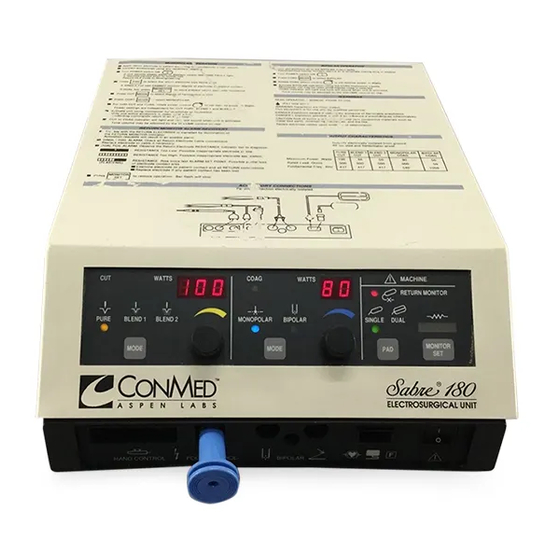
Page 20: Controls, Displays And Connectors
2.4 CONTROLS, DISPLAYS AND (8) MONITOR SET PUSHBUTTON - In dual CONNECTORS foil mode, stores present monitor resistance and clears return monitor alarm (6). (1) CUT ACTIVATION INDICATOR - Lit when a cutting output is present. (9) PAD SELECTION - Selects whether return monitor is to operate with SINGLE foil (non- (2) CUT POWER SETTING - Displays power monitoring) or DUAL foil (contact quality moni-... -
Page 21: Output Panel
Output is deliv- (6) RETURN ELECTRODE ADAPTER - ered only when foot switch is operated. Provides for use of CONMED Bioplus single full dispersive electrodes when connected to return (3) BIPOLAR OUTPUT - Accepts Conmed electrode jack (4). -
Page 22: Rear Panel
(1) MAINS INLET - Accepts AC power cordset. (3) FOOT SWITCH CONNECTOR - Accepts Aspen dual treadle foot switch such as Cat. No. (2) MAINS FUSES - Overload protection on AC 60-5104-001. See below for connections. input. (4) VOLUME CONTROL - Sets volume of acti- CAUTION: Replace only with Type T (SLO- vation tones over specified range. -
Page 23: Operating Instructions
2.5 Operating Instructions CAUTION: Always stow unused accessories in a safe, insulated location such as a test tube 2.5.1 Preliminary Set-Up or holster. 1. Ensure the Power Switch is OFF, then connect 5. Connect the foot switch to the rear of the unit the power cordset to the unit and to a properly (not required if only hand switchable monopolar grounded and polarized mating power receptacle. -
Page 24: Operation
This section contains information for ordinary upkeep of the Sabre 180. While the unit has been Surgical effects are dependent upon a number of designed and manufactured to high industry stan- factors including waveform, electrode size, elec-... -
Page 25: Cleaning
This option is available only from the 2.6.3 Periodic Inspection factory. Contact your Conmed Representative for further information. The Sabre 180 should be visually inspected at least every six months. This inspection should The default settings option may be changed quite include checks for: easily on site with the use of a few simple tools. - Page 26 (Usually accompanied by audible or visible sparking.) If the trouble cannot be corrected on site, contact CONMED Technical Service at the toll-free number shown on the inside cover of this manual. Please have the model number and serial number from the rear power nameplate along with a description of the problem, including power settings, accessories, in use, etc.
-
Page 27: Theory Of Operation
Theory of Operation Section 3.0 3.1 FUNCTIONAL DESCRIPTION 3.2 RF OUTPUT SECTION The Functional Block Diagram appears in Figure Refer to Figure 5.7 for the schematic diagram. 5.3. This diagram illustrates the functional parti- This section is located on the forward end of the tioning of the unit. -
Page 28: Aspen Return Monitor Circuitry And Software
3.2.2 Aspen Return Monitor (A.R.M.) The A.R.M. oscillator generates a low-power Circuitry and Software sinewave voltage of about 37 KHz. This frequen- cy is determined by the inductance of T4 in paral- The A.R.M. Circuit converts the electrical resis- lel with the capacitance presented by C33-34. tance appearing in the return electrode circuit into Transistors Q5 and Q6 are cross-coupled via R19 a digital value which can be processed by the... -
Page 29: Rf Output Waveforms
Figure 3.1 RF Output Waveforms PHOTO 1 PHOTO 2 Monopolar Pure, 100W , O.C. Monopolar Pure, 100W , 500 ohm 200V/div, 1uS/div 200V/div, 1uS/div PHOTO 3 PHOTO 4 Monopolar Pure Cut, 50W , O.C. Monopolar Pure Cut, 50W , 500 ohm 200V/div, 1uS/div 100V/div, 1uS/div PHOTO 5... - Page 30 PHOTO 7 PHOTO 8 Monopolar Blend 2, 50W , O.C. Monopolar Blend 2, 50W , 500 ohm 200V/div, 10uS/div 200V/div, 10uS/div PHOTO 9 PHOTO 10 Monopolar Coag, 80W , O.C. Monopolar Coag, 80W , 500 ohm 1000V/div, 10uS/div 500V/div, 10uS/div PHOTO 11 PHOTO 12 Monopolar Coag, 40W , O.C.
- Page 31 PHOTO 13 PHOTO 14 Bipolar, 50W , O.C. Bipolar 50W , O.C., Expanded Scale 100V/div, 10uS/div 100V/div, 1uS/div PHOTO 15 PHOTO 16 Bipolar, 50W , 50 ohm Bipolar 50W , 50 ohm, Expanded Scale 50V/div, 10uS/div 50V/div, 1uS/div PHOTO 17 PHOTO 18 Bipolar, 25W , O.C.
- Page 32 The A.R.M. oscillator is a dc-to-ac power con- successive approximation algorithm, to measure verter, with its major losses appearing as resistors the VARM voltage to a precision of 10mV . This in parallel with the resistance of the return elec- value is then processed along with the VARM trode circuit, R L transformed up through T4 and values for 10 and 150 ohm return circuit resis-...
-
Page 33: A.r.m. Oscillator Waveforms
Q5-C Q6-C T4-1 Figure 3.2 A.R.M Oscillator Waveforms R L = 50 ohms, 2V/div, 5uS/div U2-3 Q10-D Figure 3.3 Continuity Detector Waveforms 10V/div, 2uS/div... -
Page 34: Continuity Detector
Because patients’ and return site resistances vary The LED goes dark causing the phototransistor over a considerable range, it is not safe to assume to cease conduction and allow the signal line to that any in-range resistance indicates safe elec- be pulled to a high state by resistor network trode attachment. - Page 35 will draw collector current in proportion to its The PA consists of a single power MOSFET dri- base current, which in turn is controlled by ving the emitters of three bipolar transistors. Each VBASE and Rb. At sufficiently high base current, bipolar base has its own bypass capacitor and is Q1 saturates (collector-base voltage nearly zero), driven from a common VBASE supply.
-
Page 36: Power Amplifier Waveforms
Figure 3.5 RF Power Amplifier Waveforms The following waveforms are representative of those which appear in the Sabre 180 Power Amplifier at A4Q7-C, the collector bus COLL (A4TP16) and the FET GATE (A4TP9). 500V/DIV 500V/DIV COLL Q7-C Q7-C COLL GATE... - Page 37 200V/DIV 100V/DIV Q7-C Q7-C COLL COLL GATE 10V/DIV GATE 10V/DIV 2uS/DIV 2uS/DIV Figure 3.5e Figure 3.5f Monopolar Coag, 40W , 500 ohm Monopolar Coag, 80W , Open Circuit 200V/DIV 100V/DIV COLL Q7-C Q7-C COLL GATE GATE 10V/DIV 10V/DIV 1uS/DIV 2uS/DIV Figure 3.5g Figure 3.5h Monopolar Coag, 80W , 500 ohm...
-
Page 38: Controller Hardware
3.4 CONTROLLER HARDWARE Should a failure occur in the CPU that prevents the detection of a problem, thus allowing pro- The Controller PWB Assembly is based on the gram execution in a random manner, the Sabre 8031, a single chip, 8-bit microprocessor which 180 is designed so that the WDT detects the utilizes external program memory. -
Page 39: Power On Reset
combination of R6 and C6. In normal operation Note that the signal which causes the WDT to WDT strobes will occur after stage 1 has timed latch and ignore all subsequent WDTSTB pulses out (Q1=0) but before stage 2 times out is RYLEN-Q being high. -
Page 40: Digital I/O
3.4.3 Digital I/O The Address Decoder (U9), is used to select external I/O devices for reading and writing. The four digital ports of the 8031 (U3) are High-order address to the decoder inputs (A10, functionally assigned as follows: A11, and A12) cause the corresponding output (Y0 -Y7) to go low. -
Page 41: Base Voltage Generator
I/O, such as the PIA or NOVRAM, /PSEN U21), an inverting breakpoint summing amplifier remains high. AD0 - AD7 is an I/O bus whenev- (1/4 of U21), and power transistor A8Q1. U20 er /PSEN is high. provides the input voltage selected by the micro- processor on the bus AD0 - AD7. -
Page 42: Ifail And A.r.m. Analog Input
of VBASE at the low power settings. At lower R34 and R35 form a voltage divider to generate VDAC voltages, diode D5 becomes forward a 5V offset for U21-3 to allow single supply biased so that R9 is essentially in parallel with operation and to give a reference point for the R26. -
Page 43: Tone Generator
lines, WV0-WV7, determine which waveform is that is switched on and off at the frequency of the selected by the microprocessor, and the lower desired tone. /TONE is generated by the micro- address lines, A0-A6, determine which byte of the processor A3U3 at the desired audio frequency waveform is selected at a time. - Page 44 The following initialization sequence must be suc- Hand control, foot switch, and return electrode cessfully executed before the main working pro- inputs are monitored for changes. The validity of gram can be entered. the input conditions are checked. The following conditions are considered illegal requests and 1.
-
Page 45: Cal Mode
on the Coag Power level LEDs to indicate the declared Uncalibrated. Uncalibrated points are FAULT. See Appendix A. flagged by flashing target current displays. Restoring a point to Calibrated status requires 3.5.2 CAL Mode only that it be looked at. CAL Mode is used to gain access to and adjust When Power Calibration is exited, software veri- the calibration parameters contained in the CAL... -
Page 46: User Interface
If all tests pass, the program will loop in Lamp WDT Diagnostics (dI 2) Menu selection is no Test mode with all LEDs turned on until PAD is longer available, since RLYENA has been set to pressed again. This permits a more thorough eval- provide output, but also forcing the WDT to lock uation of lamp integrity than is possible during up permanently if WDT-Q2 ever fails. -
Page 47: Controls
A4C11. The voltage on this supply varies with mains voltage and RF output The Sabre 180 is designed to operate from 100, power, but is typically around +28 VDC at nom- 115 or 230 volt, 50-60 Hz, single phase AC inal mains and idle. -
Page 48: Rf Power Supply
Similarly, the output of A3Q1 is denoted IC U1 is a special type of switchmode control IC +28RLY; this source is regulated to +15V dc known as a Power Factor Controller (PFC). This (VRLY) by A4VR3 for use by the output selec- device operates to force the low frequency current tion relays. - Page 49 maximum. The power delivered to the output at mains voltage zero-crossing is nearly zero. Mains frequency ripple on RFSUP is controlled strictly by C2, as in a conventional mains frequency sup- ply. Capacitor C1 serves to absorb the 100 KHz peak energy, while C3 serves to minimize the magnitude of the 100 KHz current drawn direct- ly from A6T1.
- Page 50 This page intentionally left blank. 3-24...
-
Page 51: Maintenance
INFORMATION where from 0.58 to 0.62A. This section contains information useful in the 4.2.1 Ground Integrity maintenance and repair of the Sabre 180. While the unit has been designed and manufactured to Equipment: high industry standards, it is recommended that periodic inspection and performance testing be •Volt-Ohmmeter, Simpson 260 or equivalent. -
Page 52: Aspen Return Monitor (A.r.m.) Calibration Check
5. Connect the other lead to the ESU terminals Procedure: listed below, one at a time. •Either blue bipolar output jack. 1. Disconnect all accessories from the output •Either return electrode jack pin. panel. •Footswitch monopolar active jack. •Red hand controlled active jack. 2. -
Page 53: Rf Output Power
Fast blow 250V fuses rated at the meter full 4.1 correct for the load regulation characteristics scale current are recommended to prevent acci- of the Sabre 180. This results in output current dental meter failure. levels that differ from the power setting when the... -
Page 54: Rf Leakage
4.2.5 RF Leakage 2. Place the meter and resistors on the table so that they are at least 0.5m away from the unit Equipment: under test and any other conductive surface. •150 mA RF Ammeter with 1/8 A fuse. •200 ohm 10W Noninductive Resistor. 3. -
Page 55: Rf Leakage From Inactive Outputs
4.2.6 RF Leakage from Inactive Outputs CAUTION: To avoid destroying the meter, never activate output terminal connected to Equipment: Same as in Section 4.2.5 the meter. Procedure: 2. Disconnect the meter and resistor from the unit. Turn unit Power Switch OFF. 1. -
Page 56: Cal Mode General
4.3.1 CAL Mode General PAD button closure. Power down, or cycle A3S1 to RESET and back to CAL, and try again. This unit may be completely calibrated without selecting or adjusting components. Parameters 4. Normal entry to CAL Mode is signalled by a necessary to compensate for unit-to-unit manufac- continuous Lamp Test, with all display elements turing tolerances and to normalize performance... -
Page 57: Rf Output Power Calibration
4.3.2 RF Output Power Calibration Monopolar Coag calibration target current values in RF Amperes will appear in the power win- Equipment: dows. The leading decimal is assumed in the •Electrosurgical Analyzer with 300, 400 or 500 Coag window. ohm monopolar loads and 50, 100 or 125 ohm bipolar loads. -
Page 58: Aspen Return Monitor (A.r.m.) Calibration
•If HLP 10 (Incomplete Cal) appears, do NOT 21. If any power calibration targets were adjust- power down or move A3S1 yet. Press PAD. The ed, repeat the RF Output Power Checks, Section CAL Menu selection which requires attention will 4.2.4. -
Page 59: Option Selection
The Sabre 180 may be reconfigured in the field to change the mains voltage range and to change the 6. If restrapping from 230V to 115 or 100V , pre- power-up setting restore feature. -
Page 60: Power-Up Default Selection
8. While wires are inserted fully into TB1, tighten 4.4.2 Power-up Default Selection the corresponding screw securely. Verify security of the connection by pulling on the wires with The factory configures the unit to power up using the pliers. Be careful not to damage insulation. the control panel setting stored in EEPROM dur- ing the previous activation. -
Page 61: Troubleshooting
This section explains the troubleshooting aids the MACHINE lamp and redundantly disables built into the Sabre 180 and provides a guide to base and gate drive to the Power Amplifier. If the their use. Not all failures can be covered in a... -
Page 62: Diagnostic Modes
4.5.2 Diagnostic Modes pulse generator. One may select one of three pulse frequencies by using the monopolar foot Armed with a good understanding of the Theory switch. One of the selections places pulses contin- of Operation in Section 3, one can make effective uously inside the normal Watchdog Timer win- use of Diagnostic Modes in trouble-shooting dow, while the others are too early and too late. -
Page 63: Pseudo Run Diagnostics (Di2)
Since the WDT timing accuracy and ability to may result in damage to other components which interrupt RF output are verified by the micro- had previously been spared by the microproces- processor on every power up, there is no need to sor's fast response to overcurrents in RUN mode. -
Page 64: Waveform Generator Troubleshooting
proceed with this test; find the failed components If the Resistance Indicator vs. resistance test fails, and repair them. check BVARM at A3TP16 with 10 and 150 ohms connected to the Return Electrode Jacks. After successful testing of the VSENSE circuit, With 10 ohms connected, BVARM should be connect a 500 ohm 100W load resistor to the +0.88 to 0.98 Vdc and with 150 ohms, it should... -
Page 65: Continuity Detector Troubleshooting
Check the Base Voltage Generator and Waveform The open circuit voltage on the switching lines Generator for proper function before proceeding. should be about +2.7Vdc relative to the common If everything checks this far, enter dI2 (see switch line. If all four fail to cause the unit to Section 4.5.2) and select Pure Cut from the front respond, or the sense voltage is low, then the panel. - Page 66 MAINS RFSUP INPUT 100V 50-54 120V 52-56 230V 50-54 Let PFCEN open and connect a 20 ohm, 250W power resistor from RFSUP to GROUND. The voltage at RFSUP should be in between 68-76V with no more than 6V peak-to-peak, 100Hz (50Hz AC line) or 120Hz (60Hz AC line) ripple.
-
Page 67: Technical Data
ACCESS holders. Referring to Figure 5.2, the Sabre 180 is divided 5.2.1 Top Cover into two major halves, the Base Assembly, A6, and the Top Cover Assembly, A8. When the Top Refer to Figure 5.1 to locate the two Phillips... -
Page 68: Access Fastener Locations
TOP COVER RELEASE SCREWS Figure 5.1 Access Fastener Locations A1 CONTROL A2 DISPLAY PANEL POWER-UP DEFAULT A3 CONTROL JUMPER JMP1 A8Q1 A8 TOP COVER ASSY A6TB1 A8VR1 A6T1 A6R1 A4 POWER PWB A6SP1 A4 HEATSINK MTG. SCREWS A5 OUTPUT PANEL 4 PLACES A6 BASE ASSY Figure 5.2 Major Assembly and Component Locations... -
Page 69: Shield
A notch on the left side will clear the left hand heatsink insulators for damage or holes and Top Cover stud, permitting the Shield to be replace if necessary. Use only Conmed-specifica- removed fully, left side first. tion replacement insulator pads to ensure ade- quate heat transfer and dielectric strength. -
Page 70: A2 Display Pwb
CAUTION: The A3 Controller PWB contains Installation is the reverse process. Place spacer static-sensitive devices. Take appropriate static washers on the encoder bushings prior to mount- ing on the Control Panel; these washers are thick- control precautions during handling and ser- er than the flat washers used under the encoder vice. -
Page 71: Appendix Ahlp Codes And Possible Causes
APPENDIX A HLP CODES AND POSSIBLE CAUSES See Section 4.5.1 and 3.5.1 for explanation: Meaning (dependent on when performed Code as noted) When Performed Possible Causes Read/Write ability Initialization -Faulty A3U3(8031) of 8031 internal and operation memory is impaired. Program memory CRC Initialization -Faulty A3U1 (27C64) check error. - Page 72 Meaning (dependent on when performed Code as noted) When Performed Possible Causes Attempted entry Initialization -RF shield not in place into a guarded and operation -Faulty A3U3 (8031) memory location or -Faulty A3U1 (27C64) CPU failure. Watchdog Timer Initialization -Faulty A3U5 hardware does not -Faulty A3U13 disable RF drive.
Need help?
Do you have a question about the sabre 180 and is the answer not in the manual?
Questions and answers