
Related Manuals for ConMed Linvatec Hall PowerPro PRO6150


Summary of Contents for ConMed Linvatec Hall PowerPro PRO6150
- Page 1 PowerPro The Hall Pneumatic Handpieces ® ® Instruction Manual (PRO6150, PRO6175, PRO6185) PRO6150 PRO6175 PRO6185...
- Page 2 Proprietary Information This manual contains information deemed proprietary to Linvatec Corporation. The information contained herein, including all of the designs and related materials, is the sole property of Linvatec and/or its licensors. Linvatec and/or its licensors reserve all patent, copyright and other proprietary rights to this document, including all design, manufacturing methodology and reproduction.
-
Page 3: Table Of Contents
Table of Contents Page INTRODUCTION Intended Use ............1 General Warnings . - Page 4 Table of Contents Page MAINTENANCE Cleaning and Sterilizing ..........15 3.1.1 Cleaning Precautions .
-
Page 5: Introduction
INTRODUCTION General Warnings t is recommended that personnel study this 1. This equipment is designed for use by med- manual before attempting to operate, clean, ical professionals completely familiar with ® the required techniques and instructions for or sterilize PowerPro Pneumatic Hand- use of the equipment. - Page 6 7. Always inspect for bent, dull or dam- aged blades or drill bits before each use. Do not attempt to straighten or sharpen. Do not use if damaged. After use, dispose of properly. 8. Do not attach, insert or remove accessories or attachments while the handpiece is oper- ating.
-
Page 7: Symbol Definitions
Indicates the forward Symbol Definitions position for the PRO6150 Modular Handpiece. Attention, consult accompa- Indicates the “open” or nying documents. “lock” direction for the PRO6175 Oscillator Type B equipment. handpiece blade collet mechanism. Single Use Only. No user service recom- mended. -
Page 8: Powerpro Pneumatic Modular Handpiece (Pro6150)
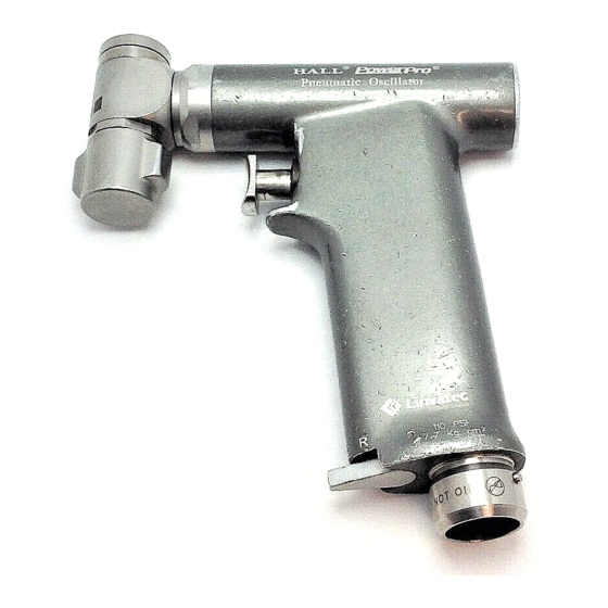
PowerPro PowerPro Pneumatic Modular Pneumatic Oscillator Handpiece (PRO6150) Handpiece (PRO6175) ❶ ❶ ❷ ❷ ❸ ❹ ❺ ❸ ❻ ❹ ❶ ❶ Attachment Collet-Lock — Twist to Blade Locking Collet — Holds and locks release and remove attachments from the the blade in place. -
Page 9: Powerpro Pneumatic Reciprocator Handpiece (Pro6185)
❸ Activation Trigger — Used to activate the PowerPro Pneumatic handpiece. Depress when the safety/direc- Reciprocator Handpiece tion lever is in the “run” position to operate (PRO6185) the handpiece. ❹ Safety/Direction Lever — To operate the handpiece, place in the “run” position. ❶... -
Page 10: Installation And Operation
Nitrogen is readily available from gas supply INSTALLATION and houses in H cylinders holding slightly more than OPERATION 300 cubic feet (8.50 cubic meters). Initial set-up costs are relatively inexpensive as compared to compressed air. Nitrogen can be placed in the NOTES: operating room or in a storage area and piped 1. - Page 11 1. Prior to set-up in the operating room, open Once the regulator is securely installed, the tank valve (counterclockwise) slowly ensure the regulator knob is in the full off and allow enough gas to escape to blow out position by turning the regulator control any debris that may have accumulated in knob counterclockwise.
- Page 12 5. Insert the male Schrader end of the hose To connect the hose to the handpiece. into the female Schrader on the regulator (a) Place the handpiece in the safe posi- with an upward thrust. tion. (b) Insert the coupling end of the hose into the fitting on the bottom of the handpiece.
- Page 13 8. Before removing the instrument from the If the Hall Pneumatic Connector* is being regulator: used: (a) Close the tank valve by turning it (a) Locate the button marked “PRESS”. clockwise. (b) Depress and hold the button until the (b) Activate the instrument to bleed off audible release of residual gas is line pressure.
-
Page 14: Connecting And Removing Attachments
Connecting and Removing Handpiece Mode Selection and Attachments Operation All attachments for the PowerPro Pneumatic Modular Handpiece connect/disconnect in the PowerPro 2.3.1 Pneumatic Modular same manner. For more information, refer to the Handpiece (PRO6150) Operation PowerPro Attachment Instruction Manual or the Information Insert supplied with each attach- The PowerPro Pneumatic Modular handpiece, ment. -
Page 15: Powerpro Pneumatic Oscillator Handpiece (Pro6175) Blade Installation And Operation
(d) Blades can be positioned 45° off the PowerPro 2.3.2 Pneumatic Oscillator center line in either direction. Handpiece (PRO6175) Blade Installation and Operation 2.3.2.1 Blade Installation 1. To attach a blade: (a) Place the safety/direction lever in the safe position. (b) Rotate the blade locking knob in the direction of the arrow to the open posi- (e) Rotate the blade locking knob in the... -
Page 16: 2.3.2.2 Handpiece Operation
Move the safety/direction lever to the “run” 2.3.2.2 Handpiece Operation position. 1. Position the rotating head to the desired position. The rotating head may be set in any of 4 positions at 90° intervals for the appropriate surgical access. (a) Ensure the safety/direction lever is in the safe position. -
Page 17: Powerpro Pneumatic Reciprocator Handpiece (Pro6185) Blade Installation And Operation
(c) Completely insert the blade shank. PowerPro 2.3.3 Pneumatic Reciprocator Handpiece (PRO6185) Blade Installation and Operation 2.3.3.1 Blade Installation 1. To attach a blade: (a) Place the safety/direction lever in the safe position. (b) Rotate the blade locking knob (d) The rotating head may be set in any of counterclockwise to open the blade 4 positions at 90°... -
Page 18: Maintenance
2. To operate the handpiece, move the safety/ MAINTENANCE direction lever to the “run” position and depress the trigger. Regular and proper maintenance of your CAUTION: Do not operate the PowerPro Handpieces are the best ways to pro- Reciprocator Handpiece with the collet in the tect your investment. -
Page 19: Cleaning And Sterilizing
Cleaning and Sterilizing 3.1.2 Handpiece Cleaning Instructions Clean handpieces and attachments as soon as possible after use. 3.1.1 Cleaning Precautions 1. Remove all attachments (chucks, saws) and accessories (saw blades, bits) from the 1. Follow universal precautions for protective handpiece prior to cleaning. Keep the hand- apparel when handling and cleaning con- piece hose attached. -
Page 20: Sterilization Information
NOTES: 3.1.3 Sterilization Information The following guidelines do not guaran- tee that the device is sterile after the pro- team sterilization is safe and effective and cedure. Your institution is still has no contraindications for its use in ster- responsible for the normal sterility assur- ilizing powered surgical handpieces and ance validation. - Page 21 Minimum recommended sterilization exposure times are as follows: Table 1: Sterilization Parameters Recommended Minimum Sterilization Type Minimum Dry Time Temperature Exposure Time Sterilization Parameters for sterilizing the PowerPro Pneumatic Handpieces (PRO6150, PRO6175, PRO6185), Associated Attachments, and Hose, with or without the PowerPro PRO5090 Sterilization Case Steam Pre-vacuum 270°F (132°C)
-
Page 22: Troubleshooting
Troubleshooting Table 2: Troubleshooting Guide Symptom Possible Cause Corrective Action ♦ Regulator malfunction. ♦ Run handpiece on another regulator Lack of handpiece power. to see if the problem is the handpiece or regulator. Replace appropriate piece of equipment. ♦ Operating pressure incorrect. ♦... -
Page 23: Technical Specifications
TECHNICAL SPECIFICATIONS Linvatec Corporation is certified by TUV Product Service to EN ISO 9001 and EN 46001 and to the Medical Device Directive 93/42/EEC with certificates for Annex II, Clause 3; Annex II, section 4 and Annex V. Handpiece Environmental Requirements Operating: Ambient Operating Temperature: + 50°F to 77°F (+ 10°C to + 25°C) -
Page 24: Powerpro Pneumatic Modular Handpiece (Pro6150)
PowerPro Pneumatic Modular Handpiece (PRO6150) Speed Range: 0 - 1250 rpm Operating Speed (forward and reverse): Drill Position (FWD): 1250 ± 10% rpm (REV): 1000 ± 10% rpm Ream Position (with 5:1 attachment): 250 rpm (forward) Average Output Torque (forward and reverse): Drill Position - Forward: 30 in. -
Page 25: Powerpro Pneumatic Oscillator Handpiece (Pro6175)
PowerPro Pneumatic Oscillator Handpiece (PRO6175) Speed Range: 0 - 14,000 cpm Oscillation Range: 4.5° Height: 6.0 in. (15.2 cm) Length: 5.25 in. (13.3 cm) Weight: 1.74 lbs. (790 kg) Duty Cycle: 1 minute ON, 5 minutes OFF Operating Pressure: 110 psi running (7.7 kg/cm Recommended Power Source: Medical grade, water-pumped, compressed dry nitrogen... -
Page 26: Accessories
Accessories Description PowerPro Handpieces, Attachments and Accessories PRO6150 PowerPro Pneumatic Modular Handpiece PRO6175 PowerPro Pneumatic Oscillator Handpiece PRO6185 PowerPro Pneumatic Reciprocator Handpiece PRO2029 PowerPro Trinkle/AO Attachment PRO2030 PowerPro 5/32” (4.0 mm) Jacobs Chuck Attachment w/key PRO2038 PowerPro AO Small Attachment PRO2040 PowerPro AO Reamer Attachment PRO2041... - Page 27 Description PowerPro Handpieces, Attachments and Accessories PRO6048 PowerPro 5:1 Hudson Reamer Attachment (Intended for use with the PRO6100 Electric II and PRO6150 Pneumatic Modular Handpieces Modular Handpiece) PRO6060 PowerPro 5:1 Aesculap Reamer Attachment (Intended for use with the PRO6100 Electric II and PRO6150 Pneumatic Modular Handpieces Modular Handpiece) PRO5090 PowerPro Sterilization Case 5052-010...
- Page 32 EC Rep: Linvatec Europe B1070-Brussels, Belgium 0123 All rights reserved. Printed in USA W41-073-004 Rev. B 07/2003...
Need help?
Do you have a question about the Linvatec Hall PowerPro PRO6150 and is the answer not in the manual?
Questions and answers