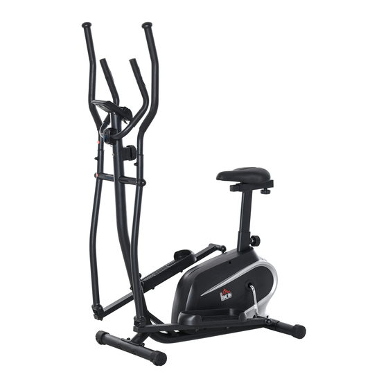
Summary of Contents for HOMCOM A90-230
- Page 1 INaoc006_UK A90-230 READ AND SAVE THIS INSTRUCTION FOR FUTURE USE ASSEMBLY INSTRUCTION...
-
Page 2: Important Safety Information
IMPORTANT SAFETY INFORMATION Please note the following safety precautions before exercising: 1、 Read all instructions before assembly & operation; 2、 Check all screws, nuts & other connections before using the bike; 3、 Do not expose the equipment to damp places, which will cause failure; 4、... -
Page 3: Exploded Drawing And Parts List
EXPLODED DRAWING AND PARTS LIST EXPLODED DRADWING AND HARDWARE PACKAGE No.1 :... - Page 4 Parts List No.1 : Description Description Rear Stabilizer Foam Grip Rear End Cap Screw M8*60 Screw M10*57 Screw M8*20 Front Stabilizer Front Post Front End Cap Bushing Washer φ19 Washer D10 Nut M10 Monitor Screwφ16×89×1/2"×20-L Screw M5*10 Washer φ Hand Pulse Bushing φ28 Washer φ6*φ12*1 Washer φ13...
- Page 5 EXPLODED DRADWING AND HARDWARE PACKAGE No.2: Part List No.2: Bearing 6001RS Magnet Grid Bearing Seat Spring Inertial Axle Screw ST3*10 Inertial Wheel Nut M6 Screw M6*60 Washer φ10.5*φ20*2 Washer Bushing Ball Shelf Idler Wheel Bowl Screw M6*9 Screw M6*30 Washer Chain Cover-L Belt Pulley Chain Cover-R...
- Page 6 Assembly Instructions 1.Preparatory work: A. Make sure there is enough space before installation; B. Confirm all of the components are all-ready before installation. ( refer to previous product exploded view which indicates the name and the location of the components); C.
- Page 7 Step 2: Screw Tension Control (54) on Front Post (42) with Washer (56) and Screw (55). Then connect Middle Wire (53) and Sensor Wire (102); and connect Tension Control (54) and Sensor Wire (60). Screw Front Post (42) on Main Frame (59) with Screw (40), Screw (41) Washer (30) Washer (34) and Nylon Nut (23).
- Page 8 Step 3: Screw Coupler Bar(28L&R) on Front Post (42) with Screw (29), Washer (30), Washer (31) and cover with Cap (24); Screw Pedal Tube(15R) on Crank (58) with Screw (14), Washer (9), Washer (11), Nylon Nut (16) and Cover with Cap (13). Screw Pedal Tube (15L) on Crank (58) with the same operation. Attn: The Screw of Pedal separate with L and R mark, Mark “R”...
- Page 9 Step 4: Screw Pedal (17) on Pedal Tube (15L&R) with Screw (18), Washer (19), Nylon Nut (20). Step5: Put the Wire Plug (68) out of Front Post (42), then put Hand pulse wire out of the Monitor Seat (42), then put Wire Plug (68) back to the hole of Front Post (42). Then screw the Middle Handle bar (50) on Front Post (42) with Screw (69), Washer (30), Washer (65).
- Page 10 Step 6: Screw Handle Bar(37L) into Coupler Bar(28L), align the holes and screw it with Screw(33), Washer(34) and Nut(35); Screw the Right Handle Bar(37R) as above operation. Step 7: Pass the Adjust Tube (72) through Seat Tube (73).Knob (74) through Washer(65),Seat Tube(73) and screw it with Adjust Tube(72).
- Page 11 Step 8: Screw Seat Tube (73) into Main Frame(59),Screw Knob(75) into Main Frame(59),the head of the knob(75) should be aligned with the Hole of Seat Tube(73).
-
Page 12: Exercise Instructions
EXERCISE INSTRUCTIONS The Warm Up Phase This st age helps get the blood flowing around the body and the muscles working properly. It will also reduce the risk of cramp and muscle injury. It is advisable to do a few stretching exercises as shown below. - Page 13 Exercise Stage This stage should last for a minimum of 12 minutes though most people start at about 15~20 minutes. After times, you can increase training strength. After exercising for a period of time, your heart rate will be close to the “target zone”(shaded part) in the graph as shown below. e: Getting in a better shape will not happen overnight and will require working out consistently.


Need help?
Do you have a question about the A90-230 and is the answer not in the manual?
Questions and answers