
Related Manuals for HOMCOM A90-200


Summary of Contents for HOMCOM A90-200
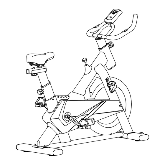
- Page 1 INada095_UK A90-200 Exercise Bike Photo may differ from actual product READ AND SAVE THIS INSTRUCTION FOR FUTURE USE ASSEMBLY INSTRUCTION...
-
Page 2: Safety Information
Please read these instructions properly before assembling or using this bike. Important information is listed, which will help you get t h e best results and ensure safe and correct assembly, use and maintenance. Safety information * This equipment is intended for home/domestic use, with a maximum holding weight 120kgs/264lbs. * This equipment is designed for adult use only. - Page 3 COMPONENTS/PARTS Please check if you have all parts as listing below. Note : Small components/parts might be pre-fitted to the larger components as to make it easier for end users to assembly the spin bike. Please check carefully on all the parts before contacting us regarding any missing components.
-
Page 4: Part List
PART LIST ITEM ITEM Monitor Front Stabilizer (with Transportation Wheels) Handlebar Saddle * Lock Nut & Washer Set Saddle Adjustment Frame Handlebar Support Tube Saddle Adjustment Knob K3 Lock Knob K1 Saddle Support Tube Resistance Knob K2 * Lock Bolt, Washer & Nut Set Water Bottle Holder(not Rear Stabilizer included) -
Page 5: Assembly Instruction
Assembly Instruction STABILIZER ASSEMBLY Divide the Front Stabilizer (with two transportation wheels) and the Rear Stabilizer, to fix them onto the main body with NO. 16 Lock Bolt, Washer & Nut Set. HANDLEBAR & MONITOR ASSEMBLY Loose NO. 5 Lock Knob K1 and insert the Handlebar Support Tube into... -
Page 6: Saddle Assembly
ASSEMBLY SADDLE Loose the Lock Knob K1 and pull it out from the rear opening tube, insert the Saddle Support Tube into the rear opening tube, then tighten the Lock Knob when the Saddle Support Tube is at desired position. Saddle Adjustment Attach Frame to the... -
Page 7: Care And Maintenance
Care and maintenance * Examine the equipment periodically in order to detect any damage or wear which may have been produced. * Lubricate moving parts with light oil periodically or prevent premature wear. * Inspect and tighten all parts before using the equipment, replace any defective parts immediately, and do not use the equipment again until it is in perfect working order.
Need help?
Do you have a question about the A90-200 and is the answer not in the manual?
Questions and answers