
Related Manuals for HOMCOM A90-259


Summary of Contents for HOMCOM A90-259
- Page 1 INaoa007_UK A90-259 READ AND SAVAE THIS INSTRUCTION FOR FUTURE USE ASSEMBLY & INSTRUCTION MANUAL...
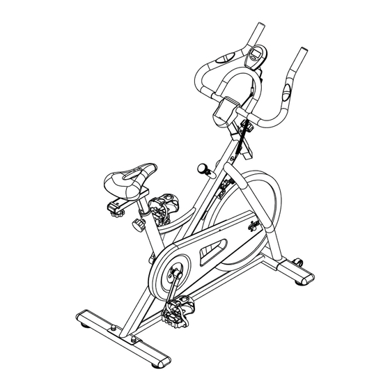
- Page 2 EXPLOSIVE VIEW...
- Page 3 SPARE PARTS LIST Description Description Inner Hexagon Bolt Main Frame M10*15mm Upright Dome Nut M10 Seat Support Brake Knob Front Stabilizer Flat Washer M10 Rear Stablilizer Flat Washer M8 Seat Slider Spring Washer M8 Handlebar Knob M8 Seat Bushing Left Crank Pulse Sensor Wire Right Crank Upper Sensor Wire...
- Page 4 ASSEMBLY INSTRUCTION Step 1 Attach Front Stabilizer(04) to Main Frame(01), using two Inner Hexagon Bolts(12) and two Flat Washer(18). Attach Rear Stabilizer(05) to Main Frame(01),Using two Carriage Bolts(13),two Flat Washers(17) and two Dome Nuts(15).
- Page 5 Step 2 Attach the Seat(08) to Seat Slider(06), then put it onto Seat Support(03), tighten with a Flat Washer(18), Spring Washer(19) and Knob(20). Insert this Seat Support assembly to Main Frame(01), secure by using one Adjustable Knob(11). Noted:The Adjustable Knob(11) is pre-assembled,when using it please follow below: 1:Turn knob counter-cloclwise three times.
- Page 6 Step 3 Attach Handlebar(07) to Upright(02) using two Inner Hexagon Bolts(14) and two Flat Washers(17),then put the Handlebar Cover(27) onto Handlebar(07) as showing. Insert Upright assembly to Main Frame(01) secure by using Adjustable Knob(28).
- Page 7 Step 4 Attache the Monitor(24) to the bracket of Handlebar(07).Connect the Upper Sensor Wire(23) to Pulse Sensor Wire(22) and Lower Sensor Wire(25) to the back of the Monitor(24). Tighten the Left Pedal(10L) counter-clockwise onto the Left Crank(09L), and tighten the Right Pedal(10R) clockwise onto the Right Crank(09R) .
Need help?
Do you have a question about the A90-259 and is the answer not in the manual?
Questions and answers