Table of Contents
Advertisement
Quick Links
Advertisement
Table of Contents

Related Manuals for XAG M500 Remote Sensing UAS


Summary of Contents for XAG M500 Remote Sensing UAS
- Page 1 M500 Remote Sensing UAS User Manual Version 1.0...
- Page 2 To User Dear user, thank you for choosing XAG's product. For safety purposes and better user experience, it is highly recommended that you read this manual carefully and strictly follow the instructions hereof. Contact Us If you have any questions about this document, please contact our Technical Support team via email:...
-
Page 3: Table Of Contents
Contents Safety Guidelines Disclaimer Introduction List of Items Main Components Systems Super X4 Flight Control System Positioning System Communication System Obstacle Avoidance Radar System Terrain-following Radar System Imaging System Aircraft Unfold Aircraft Unfold Landing Gears Install Camera Install Battery Smart Battery Power On/Off Check the Battery Level Charge the Battery... - Page 4 "Xpilot" App App Overview Appendix Status Indicator Specifications...
-
Page 5: Safety Guidelines
Safety Guidelines · Please get acquainted with the flight location in advance, which should be far away from obstacles and crowds and free from unsafe conditions. · NEVER operate while drowsy, drunk or in a poor mental state so as to prevent accidents. ·... -
Page 6: Disclaimer
6. To the maximum extent permitted by law, XAG shall not be liable for all losses arising from user's op- eration not following the instruction in the User Manual/Instruction Manual. Also, XAG shall not be... -
Page 7: Introduction
With a built-in RTK+GNSS Dual Positioning System and a more intelligent and powerful "brain" - Super X4 Flight Control System, XAG® M500 Remote Sensing UAS leaps forward in both high-precision mapping owing to its centimeter-level positioning and real-time map generation. WiFi/4G dual-path ensures smooth communication at different distances and a safer flight. -
Page 8: Main Components
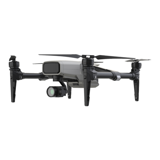
Main Components 1. Propeller 2. Collision Avoidance Radar 3. 4G Antenna 4. Terrain-following Radar 5. RTK Antenna (one on the left, one on the right) 6. Arm 7. Motor 8. Landing Gear Fastener 9. 2.4/5.8GHz Antenna 10. Camera 11. SIM Card Slot 12. -
Page 9: Systems
RTK + GNSS Dual Positioning System with real-time centimeter-level accuracy delivers high-precision data to support various missions. The built-in 4G module enables the drone to be covered by the XAG Cloud RTK network, ready for operation without an additional portable base station. With the handheld terminal accessing the XAG Cloud RTK network as well, high-precision positioning is guaranteed by differential data transmission via WiFi/4G dual-path. -
Page 10: Terrain-Following Radar System
HD map by combining the results in the cloud/Feitu/local server. Upon automated field boundary/crop detection via XAI Smart Agricultural System, the map can be imported to an XAG agricultural drone for autonomous plant protection. A built-in 1 inch 20MP CMOS sensor brings about high-resolution imaging while the mechanical global shutter sees that photos are free from distortion, fuzziness or rolling shutter effect. -
Page 11: Aircraft
Aircraft Unfold Aircraft Spread out the arms as shown below until you hear a click. Unfold Landing Gears Spread out the landing gears as shown below until you hear a click. Note Please see that the landing gears are securely locked www.xa.com/en... -
Page 12: Install Camera
Install Camera Align the white dot on the camera plate with the "unlock" mark on the chuck. Turn the camera plate clockwise until the white dot is aligned with the "lock" mark. White Dot Note Please switch off the aircraft before fitting/removing the camera, or it may cause damage to the components. Please switch off the aircraft before inserting/removing SIM card and SD card. -
Page 13: Install Battery
Install Battery Insert the battery as shown below until you hear a click. Note Please make sure that the battery is firmly inserted before the flight. Otherwise, it will result in sudden power loss during the flight and cause an accident. Beware of the travel switch when handling and storing the battery separately. -
Page 14: Smart Battery
Smart Battery With 6 high voltage lithium polymer power batteries and a BMS module, C500 Smart Battery, specially designated for M500, provides real-time information such as voltage, current and temperature as well as charging protection. It gives immediate feedback to the load side during use. In case of battery low or failure, it will send an emergency stop signal initiatively to ensure the electrical safety of the load side. -
Page 15: Charge The Battery
Battery Level Indicator (Green Lights) LED Behavior Status Description 1 Flashing Light 1 Solid Light 20% 40% 2 Solid Lights 40% 60% 3 Solid Lights 60% 85% 4 Solid Lights 85% 100% 2 Double Flashing Lights Auto Lock Locking for low battery, it will automatically unlock after being charged (voltage over 3.2V). - Page 16 To protect our environment, please properly dispose of the battery as required by the local laws and regulations. DO charge the battery with the XAG official charger. Otherwise, the user shall be held accountable for any consequence arising therefrom. www.xa.com/en...
-
Page 17: Remote Controller
Remote Controller Diagram TypeC, TF CARD, HDMI Interface Antenna Left Front Button Right Front Button Joystick Strap Ring Indicator Hover/Return Photo/Video Power Button Screen Speaker Charging Port Camera Air Outlet Air Inlet USB Wireless Modem Cover www.xa.com/en... -
Page 18: Power On/Off
Power On/Off When the remote controller is off, long press the power button for at least 2 seconds until all the indicators flash with green light simultaneously, followed by another long press until the speaker beeps and the second indicator goes flashing green. When it turns solid green, the remote controller turns on. When the remote controller is on, long press the power button for at least 2 seconds until all the indicators flash with green light simultaneously, followed by another long press until the screen reads "Powering Off"... -
Page 19: Unfold Antennas
The second indicator (the lower one) shows the current status. The table below describes its behavior. Status LED Behavior Description Solid Green Normal Flashing Green Powering on/off Solid Red Abnormal When the remote control is updating, both indicators are on, which is described as follows. Update LED Behavior Description Updating... -
Page 20: Install Usb Wireless Modem
Note It is recommended to adjust the antenna side-on to the aircraft as the side of the antennas sends out the strongest signal. The optimum signal coverage is shown as below. Install USB Wireless Modem Insert the SIM card into the USB wireless modem. Open the USB wireless modem cover, insert the modem, and close the cover firmly. - Page 21 Flight Controls Camera Press "Left Front Button", "Right Front Button" and "Photo/Video Button" to control the gimbal camera in real-time. · Pitch up & down · Short press the "Left Front Button" to rotate the camera downward slowly while long press quickly. ·...
- Page 22 Stop Motors After the aircraft lands, pull the throttle to the lowest position and hold it until the motors stop. Hover & Return During the flight, short press the Hover/Return button to hover the aircraft while long press to have it return.
-
Page 23: Joystick Mode
Joystick Mode The Joystick Mode is divided into Japanese Hand, American Hand and Chinese Hand. Japanese Hand (Mode 1) Forward Left Joystick Right Joystick Ascend Descend Backward Turn Right Left Turn Left Right American Hand (Mode 2) Forward Ascend Left Joystick Right Joystick Descend Backward... -
Page 24: Xpilot" App
"Xpilot" App App Overview Home Screen 1. My Device 7. Mission Screen Tap to get to the device list. : Tap to enter the flight mission screen. 2. Remote Control Status 8. Flight Results : Ta p t o v i e w t h e s t a t u s o f t h e : Tap to view flight results. - Page 25 Flight Screen 1. Home Screen 7/8. Flight Commands : Tap to return to the home screen. Tap to hover or return. 2. Aircraft's Name 9. Flight View Tap to view device details. Tap to switch video transmission images. 3. Connection Status 10/11/12/13.
-
Page 26: Appendix
Appendix Status Indicator Get to know the current status of the aircraft by checking the Flight Status Indicator (Tail Light). Details are as follows: Tail Light LED Behavior Status Description Alternate Flashing Weak GPS signal or compass interference Red/Green Manual Mode Double Flashing Strong GPS signal Green... -
Page 27: Specifications
Specifications XCam 20 Pro Gimbal Camera Aircraft Image Sensor: 1 inch CMOS Sensor Effective Pixels: 20 Megapixels Model: M500 Remote Sensing UAS Lens: Focal Length f=10.6mm (Equivalent Takeoff Weight: 2.55kg 28.9mm) Wheelbase: 492mm ISO Range: 100 - 3200 Max. Takeoff Altitude: 6000m Mechanical Shutter: 1/30-1/2000 s Max. - Page 28 This manual is subject to update without prior notice. ©Guangzhou Xaircraft Technology CO., LTD. All Rights Reserved. All information of this User Manual (including but not limited to any text description, illustrations, photos, methods, processes, etc.) belongs to Guangzhou Xaircraft Technology CO., LTD and is protected by copyright law. Without written authorization, no individual or institution is allowed to reproduce, extract, translate, distribute, or otherwise reproduce or quote any content hereof.
Need help?
Do you have a question about the M500 Remote Sensing UAS and is the answer not in the manual?
Questions and answers