
Related Manuals for Telos Zephyr


Summary of Contents for Telos Zephyr
- Page 1 Digital Network Audio Transceiver The Best Way to Hear from There™ User’s Manual Manual Version: 3.0, November, 1997...
- Page 2 The URL is: http://www.zephyr.com. Feedback We welcome feedback on any aspect of the Zephyr or this manual. In the past, many good ideas from users have made their way into software revisions or new products.
- Page 3 Test Lines To aid you in testing and demonstrating your Zephyr Telos Systems has the following test numbers available: • USA: +216 781.9310, +216 781.9311 (Layer III Dual transmit @ 32 KHz sample rate) • Germany: (49) 81 61 42 061 Dial this number twice (Layer III Dual transmit @ 32 KHz sample rate) •...
- Page 4 Refer all servicing to qualified personnel. IMPORTANT NOTE! The Zephyr memory backup is powered by Lithium battery BT-1. The following precautions must be followed when working on the Zephyr motherboard or when this battery is replaced: 1) Do not short the battery terminals (or traces connected to these terminals) together.
- Page 5 interference. If it does, the user will be required to eliminate the interference at the user’s expense. NOTE: Objectionable interference to TV or radio reception can occur if other devices are connected to this device without the use of shielded interconnect cables. FCC rules require the use of only shielded cables.
-
Page 6: Table Of Contents
Connecting to The ISDN Line Powering Up Basic Configuration Placing Your First Call (to Yourself) Your Next Call, to Telos What’s Next? Where to find answers to frequently asked questions INTRODUCTION (SECTION 2) THE BEST WAY TO HEAR FROM THERE™... - Page 7 ZEPHYR AT A GLANCE (SECTION 3) FRONT PANEL Display Status LEDs LCD and Pushbuttons REAR PANEL Slot Positions ISDN V.35/X.21 Send (Input) Audio Receive (Output) Audio Phones RS-232 Parallel Port AES/EBU Remote Panel AC Power INSTALLATION & BASIC OPERATION (SECTION 4)
- Page 8 NON-ISDN NETWORKS (SECTION 6) SWITCHED 56 MORE NETWORK OPTIONS Primary Rate ISDN Digital Data Service (DDS) Other Possibilities USING THE ZEPHYR WITH NON-ISDN NETWORKS V.35/X.21 Network Connection AUDIO CODING (SECTION 7) OVERVIEW Introduction to Audio Coding Basic Principles of Perceptual Coding...
- Page 9 DETAILED MENU REFERENCE (SECTION 8) MENU OVERVIEW Menu Summary Using the Menus DETAILED MENU REFERENCE Utility Menu Dial Menu Auto-Dial Menu Drop Menu Volume Menu Help Menu Special Start-up Functions Utility Menu - The Complete Works REMOTE CONTROL (SECTION 9) CONNECTING TO A COMPUTER SYNTAX USED IN THIS MANUAL COMMANDS AND FUNCTIONS...
- Page 10 ZEPHYR LIMITED WARRANTY APPENDICES (SECTION 15) ABOUT AUDIO LEVELS CODEC COMPATIBILITY INFORMATION FINDING PUBLIC ZEPHYR SITES ISDN BRI, ZEPHYR, AND YOU Ordering ISDN List of Known Working SPIDs by Telephone Company MENU’S AT-A-GLANCE; Utility Menu Summary FAXABLE ISDN BRI LINE ORDER FORM...
- Page 11 The Zephyr is a result of what were once my personal passions, and what have now become what MBA types call our “core corporate competencies,” Digital Signal Processing and telephones for broadcast.
-
Page 12: Conventions Used In This Manual
Conventions Used in this Manual We use the following symbols to draw your attention to particularly important points. IMPORTANT! This information is essential to getting the Zephyr to work, or to prevent damage to it. To avoid headaches please read these. -
Page 13: Quick Results! (Section 1)
SECTION 1 QUICK RESULTS! Table of Contents... -
Page 14: Who Can Use This Section
We know how you feel. You don’t want to sit around and read a manual. You want to plug- in your new Zephyr and hear what it can do. You want to connect to a distant location and be amazed at how good audio can sound over the telephone. -
Page 15: What You Need Before You Start
Europe and Asia. Cable required: A large, telephone- type modular cable with eight wires that fits into the upper (or only) jack on the Zephyr and a jack on the NT1 that is labeled “Terminal.” Your NT1 should have been wired to the ISDN line by your Telco. -
Page 16: Information On Your Isdn Line
Information on your ISDN line Zephyr needs to know some things about your ISDN line to work properly. Your ISDN circuit consists of two, digital “B channels”. Just like a regular telephone line, these channels have telephone numbers so that you can send and receive calls. - Page 17 ISDN TIP! European users should disregard all references to SPIDs. Euro ISDN does not have SPIDs! If your ISDN configuration requires MSNs they may be entered in the MSN/SPID 1 & 2 screen. ✔ ✔ ✔ ✔ DN numbers (7 digits), if applicable: Line 1 Line 2 If your ISDN line is connected to an internal phone system that requires you dial a...
-
Page 18: Success, Step-By-Step
Using a large RJ- 45 style, telephone- type modular cable with eight wires, interconnect the upper (or only) jack on the Zephyr and a jack on the NT1 that is labeled “Terminal.” This cable must have eight wires and is provided with the Zephyr. -
Page 19: Powering Up
If you have a proper audio connection and are feeding an audio signal to the Zephyr, you will see activity on the two SEND meters on the left- side of the front panel. (With some mono transmit modes, there will be no indication on the Channel B send meter.) - Page 20 Quick Start, you must erase all of the previous settings. Before you go to the next step, check with the last person who used this Zephyr to be certain that he or she no longer needs these settings.
- Page 21 In addition, you should observe the following: • The SYNC lamp will be glowing red on the left side of your Zephyr’s front panel. • If your Zephyr has an internal NT1, the little green light (at the bottom left, of...
-
Page 22: Placing Your First Call (To Yourself)
• If you have a Zephyr with an internal NT1, the green status LED (near the jack, on the rear panel) should be on solid. If it is not, you have a very basic line problem – see section 10 (Advanced Problem Solving) of the manual for more advice and guidance. -
Page 23: Your Next Call, To Telos
LCD display will be illuminated, the receive LOCK lamp will light, and, if you are sending audio down your Zephyr, you will see activity on both the send and receive meters. If connected to your studio audio gear, you should be able to hear your feed on the receive audio outputs or your headphones. -
Page 24: What's Next
If you want to skip around the manual a bit, the chart that follows can tell you where to find answers to the most frequently asked questions. Further assistance in using your Zephyr can be found in the HELP menu, which may be accessed at any time. When the <HELP> button is pressed, the LCD display provides information on the item that was previously displayed. -
Page 25: Where To Find Answers To Frequently Asked Questions
How should the remote site device be Codec Compatibility Info: configured when it is not a Zephyr? Appendix How can I connect the Zephyr to a computer? Remote Control: Section 9 How do I contact Telos? Customer Support: Page 2... - Page 26 This page intentially left blank Section 2 INTRODUCTION...
-
Page 27: Introduction (Section 2)
SECTION 2 INTRODUCTION Section 2 INTRODUCTION... -
Page 28: The Best Way To Hear From There
THE BEST WAY TO HEAR FROM THERE™ Introducing Zephyr Zephyr makes transmitting CD- quality audio as easy as sending a fax. Integrating the most advanced audio coding and digital telephone technologies in a single unit, Zephyr is the perfect choice for news, sports, music, and production. -
Page 29: Features And Benefits
Features and Benefits • Zephyr is specifically designed for use with one ISDN circuit and other low bit- rate transmission paths. Each Zephyr unit serves as both a transmitter and a receiver. It is the premier product in a complete range of ISDN audio products that includes the ZephyrExpress™... - Page 30 Zephyr using a computer or a remote unit via a modem. • AES/EBU digital input/output interface module provides maximum flexibility for connection with digital studio equipment. Sample rate conversion is available on both input and output paths.
-
Page 31: Overview: Zephyr, The Box
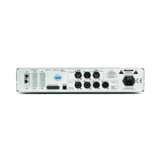
• Utility menu controls transmit and receive modes, data rate, headphone volume, and other features. Rear Panel Hardware connections to Zephyr are straightforward: • ISDN terminal adapter is built- in. The ISDN line is simply connected to the modular jack. -
Page 32: Ordering Guide
5 DSP Unit required to transmit ISO/MPEG Layer II 2- line “Mono- 128” mode AES/EBU modules require factory installation and possible extra cost motherboard upgrade Contact Telos Systems for details on upgrade kits and cables for the data port. Zephyr Transmission Modes Modes can be individually selected for the transmit and receive paths. -
Page 33: Introducing Isdn
ISDN BRI is installed in your facility, each line is brought in on only one pair of wires. ISDN is full duplex and calls are dialed and routed just like analog calls. Zephyr uses the two “B” channels for bi- directional audio (transmitted as digital data), ancillary RS- 232 data, and inter- unit signaling. - Page 34 The Zephyr Terminal Adapter Zephyr has made connection to ISDN easy by incorporating both a codec and a terminal adapter into a single integrated unit. In the past, you needed to connect external terminal adapters to your codecs. Unlike other manufacturers who buy ISDN terminal adapters to build into their codecs, we developed our own.
-
Page 35: Questions And Answers About Audio Coding
The ISDN analyzer function provides easy- to- read error messages when a problem occurs on the ISDN line. Connecting a computer to the serial port allows complete analysis of the ISDN line status for Telos or your telephone service provider to troubleshoot. - Page 36 The final report of ITU Radiocommunication Task Group 10/2 clearly recommends Layer III for ISDN bit rates, and the daily experience of Layer III users further supports those findings. Of course, the best way to know how good Layer III sounds in Zephyr is to hear it for yourself.
-
Page 37: About Telos Systems
About Telos Systems At Telos, our mission is to give you the tools to exploit the full potential of available analog and digital bandwidth. Wherever telecommunications and broadcasting meet, you’ll find us. With that in mind, we’ve compressed a lot of innovation into the decade since introducing the Telos 10 digital hybrid talk show system, the first broadcast product to use DSP. - Page 38 This page intentionally left blank Section 2 INTRODUCTION...
-
Page 39: Zephyr At A Glance (Section 3)
SECTION 3 ZEPHYR AT A GLANCE... -
Page 40: Front Panel
LEDs at the encoder. Limit Indicators The Zephyr has a send audio limiter which serves to keep the usual “digital nasties” from happening when the send program signal grows instantaneously too large. This is a very fast and very “tight”... -
Page 41: Lcd And Pushbuttons
P H O N E S 9 0 - 26 0 V A C Slot Positions The Zephyr employs a modular architecture, permitting future expansion and flexibility. There are three slots for expansion cards, each of which allow connector access through the rear panel. - Page 42 • Connect to an external NT1. • Allow connection to another ISDN device, such as another Zephyr or an ISDN telephone. • If using the PS- 2 power available on the S interface, the jumper JP- 1 on the ISDN terminal adapter card must be between Pins 1 and 2.
- Page 43 Offers interface to digital bitstreams, primarily for non- ISDN applications. Both V.35 and X.21 equipment can be accommodated with the use of the appropriate cable. More information can be found in manual section 6 (Non- ISDN Networks.) Section 3 ZEPHYR AT A GLANCE...
-
Page 44: Send (Input) Audio
In MONO transmit modes the audio appearing from the “A” input will be used. CURIOSITY NOTE! The Zephyr has the more common pin-outs used for 3 pin XLR inputs/outputs. You can easily remember the correct signals when wiring connectors using the phrase “George Washington Bridge”. - Page 45 4 dBu nominal (see appendix for additional information on levels). External gain stages or pads may be required. • Tight control of the level before the Zephyr must be maintained or digital clipping of the A/D converter could result. Section 3...
-
Page 46: Receive (Output) Audio
MONO feed is sent into your stereo equipment. CURIOSITY NOTE! The Zephyr has the more common pin-outs used for 3 pin XLR inputs/outputs. You can easily remember the correct signals when wiring connectors using the phrase “George Washington Bridge”. -
Page 47: Phones
Reference). This jack is wired in parallel with the front panel headphone jack. RS-232 R S 2 3 2 R E M O T E FUNCTION Rx (Computer to Zephyr) Tx (Zephyr to Computer) DTR (Zephyr ready output) Ground HOT TIP! -
Page 48: Parallel Port
See the manual section 8 (Detailed Menu Reference) for details on using the panic dial DEEP TECH NOTE! The Zephyr’s “universal” logic input circuit can be used with switch or relay closures, voltage levels up to 24 Vdc, or logic outputs –... - Page 49 • Rcv lock • Line 1 active • Line 2 active • Lines 1 & 2 active • Lines 1 or 2 active For additional information refer to manual section 8 (Detailed Menu Reference). Section 3 ZEPHYR AT A GLANCE...
-
Page 50: Aes/Ebu
The SYNC OUT is a buffered version of the SYNC IN signal. More information about the various modes is in section 4 (Installation & Basic Operation) and section 8 (Detailed Menu Reference). Section 3 ZEPHYR AT A GLANCE... -
Page 51: Remote Panel
The power supply has a universal AC input, accepting a range from 100 to 240 Vac, 50- 60 Hz. A fuse is located inside, on the power supply circuit board. Section 3 ZEPHYR AT A GLANCE... - Page 52 This page intentionally left blank. Section 4 INSTALLATION & BASIC OPERATION...
-
Page 53: Installation & Basic Operation (Section 4)
SECTION 4 INSTALLATION & BASIC OPERATION Section 4 INSTALLATION & BASIC OP... -
Page 54: Introduction
INTRODUCTION This section offers a guide to the basic operation of the Zephyr in a format which is mostly tutorial in style. As in Quick Results, you are led through the steps which result in a successful connection, but additional options are explored, and a more thorough description of common functions and modes is given. -
Page 55: The U And S/T Interface (Usa)
Telco line and the S/T jack is unused. The Zephyr's S/T interface is always active, and may be used to parallel additional ISDN terminal equipment, such as an additional Zephyr or ISDN phone set, to the line. The internal NT1 operates just as if it were an external box in order to permit this to occur (see diagram, below). - Page 56 IMPORTANT! If using an external NT1, or connecting another device, be sure to check power arrangements. The Zephyr provides “PS- 2” power on the S/T jack. If your NT1 or other device has an external power supply it is essential that the 2 power leads not be interconnected or damage to the Zephyr, external equipment, or both, may occur.
-
Page 57: The S/T Only Interface (Europe And Elsewhere)
The S/T Only Interface (Europe and Elsewhere) The Zephyr connects to the NT1 at one of the TERMINAL jacks. Use only an 8- conductor cable. Unlike the USA version, this ISDN interface does not provide power to the NT1 and it must be provided independently. -
Page 58: Connecting Audio
If required, adjustment may be made by selecting the Volume menu. The Zephyr can accept either line or microphone level. There is a rear panel switch located near the input connectors for selection of the level mode. -
Page 59: Getting Help
<NO -> buttons while powering-up the unit. You can then use the <SEL> buttons to change the backlight and the <YES +> and <NO -> buttons to adjust the contrast. The Zephyr should then be switched-off and on again to return to normal operation. -
Page 60: Using The Menu System
Pressing help repeatedly... • Displays help about the selected menu item • Displays status screen • Displays help about the status screen • Displays status screen etc. As illustrated below: <Help> Menu Help for <Help> <Help> Status Status Screen Menu Screen Screen Help <Help>... - Page 61 SE L Headphones Phone Speaker Send [ +4 dBu] SE L YE S <+/-> change UT IL H EL P V O L The value is at the default +4 dBu. The <NO- /YES+> buttons are used to change the input gain: SE L Headphones...
- Page 62 The first screen looks like this: SE L [ L3 DUAL L3 MONO SE L YE S Rate 56kbps 32kHz <NO> options H EL P UT IL V O L Note that the prompt is different from the one in the Volume screen. Use <NO- > to cycle through the options and <YES+>...
-
Page 63: Setup To The Isdn Line
LCD contrast, LCD backlight, Ancil channel Screen 9: Copyright & version numbers & date The first set of items you will need to use are those required to set the Zephyr to conform to the characteristics of your ISDN line... Setup to the ISDN Line Network Confirm that you are set to use the Zephyr’s internal ISDN interface. - Page 64 SPID 1 & 2: > < <YES> store ISDN TIP! European users should disregard all references to SPIDs. Euro ISDN does not have SPIDs! If your ISDN configuration requires MSNs they may be entered in the MSN/SPID 1 & 2 screen.
- Page 65 SPID 1 & 2: >21678193100111 < [21678193110111 Number stored ISDN TIP! The SPID is not required for PTP and ETS300 Telco modes. More on this in subsequent sections. ISDN TIP! Usually the SPID is the area code+phone number+0101. But we have seen some which include a two-digit prefix and a two- digit suffix, and many other variations are possible.
- Page 66 Protocol Finally, we have to tell the Zephyr which protocol the ISDN line is using. You should have gotten this information from the phone company. Press the <UTIL> button until you get to this menu screen: Telco Panic Dial <NO> options The screen indicates the mode PTP.
- Page 67 |ISDN These should appear in sequence within about 10 seconds. If you do not get to Ready, Ready something is wrong, either with the line or the Zephyr setup. ISDN TIP! Recall that the ‘AT&T PTP’ Telco mode does not require SPIDs, so the line status should go immediately to ‘Ready’...
-
Page 68: Making A Call
1) Remove both SPIDS and both directory numbers 2) Set Telco to PTP 3) Have another Zephyr call either of your phone numbers twice. They should be able to connect. 4) The line will now function normally for outgoing calls until Zephyr is rebooted or the ISDN connection is reinitialized. - Page 69 The first LCD line indicates that you’ll be dialing in “ZEPHYR” mode on ISDN line 1. (Zephyr mode means that we want a hi- fi call to another codec, rather than one to a regular phone.) These are the defaults. If we wanted to change either the mode or line channel, pressing the <- NO>...
- Page 70 Ready|56 kbps 32kHz |ISDN The call is now connected and Zephyr is displaying the call duration timer. This is what we’ve been waiting for! You will hear an audible ‘bleep,’ and the Line 1 LED will come on, indicating the successful connection.
- Page 71 Troubleshooting), section 5 (ISDN) and section 4 (installation & Basic Operation) To aid troubleshooting, here is the meaning of each step: No line connected, or connected to wrong jack on Zephyr inact: Before sending SPID to ISDN network, or after seeing external NT1...
- Page 72 Drop: [ BOTH LINES ] <NO> or <DROP> Zephyr tries to guess whether you want to drop one line or both, depending upon the Xmt and Rcv modes. In this case, the modes are Stereo, and BOTH LINES has been selected for you.
-
Page 73: Using Auto Dial
Telos Test Line <+/-> or <AUTODIAL> There are 50 possible auto dial set- ups. This example screen indicates that the Telos test line is programmed into the #1 set- up. With the brackets around the Auto Dial number value, press the <-NO> or <YES> button to see other set- ups:... - Page 74 Auto Dial: Display [NUM1] 12167819310 <+/-> or <AUTODIAL> It’s possible to have two numbers stored (for a two- channel call), and you can see the second by choosing NUM2 by pressing<YES +> again: Auto Dial: Display [NUM2] 12167819311 <+/-> or <AUTODIAL> The final value for Display shows the stored mode for this set- up: Auto Dial: Display...
-
Page 75: Storing Setups
00:01|56kbps 32kHz |ISDN Note that with a unit properly pre- programmed, it is possible to get a Zephyr on the air with just two presses of the <AUTO DIAL> button; one to get the menu, and the second to go. -
Page 76: Calls To A Regular Phone
Calls To A Regular Phone (G.711 calls) One of the great features of the Zephyr with its internal ISDN interface is that you can make voice calls to regular telephones, not just to other codecs. In fact, you can make a mono Zephyr hi- fi call on one channel and a voice call on the other simultaneously. - Page 77 In our example, we do not have a coded, hi- fi connection yet going, and we just want to make a call before doing so – maybe to let someone know that a Zephyr connection is on the way. This means that we can use ISDN line 1, the default. But we want to change...
-
Page 78: Setting Audio Coding Modes
The transmit mode at this end must match the receive mode at the other end, and vice- versa. The values given in the example will work with the Telos test line – which is likely to be one of your first calls: IMPORTANT! Note that the Rcv modes are a subset of the Xmt modes;... -
Page 79: Dual Site Operation
7 (Audio Coding Principles). COMPATIBILITY TIP! On the Zephyr, we refer to the per-line bitrate. In the stereo modes, the total bitrate is two times this number. This can be confusing because some other codecs use the total, rather than the per-line value. -
Page 80: Dealing With Delay
Zephyr Xmt-To-Rcv Mode Compatibility Table This table shows which Zephyr Xmt and Rcv modes may operate with each other, the resulting audio bandwidth for each, and information which describes what happens to the audio channels when they are output from the decoder. -
Page 81: Phones And Remotes
Problem. The answer is to make sure you have the best possible hybrid with the maximum trans- hybrid loss. If it has variable override (caller ducking), you could increase the amount when these remotes are in progress. Main Program Output Other Sources Zephyr for music, etc. Telephone Trans- Mix-Minus mission... -
Page 82: Aes/Ebu
MONO Rcv for this path rather than using the slower L3 STEREO mode. Another trick is to use a POTS call (either by Zephyr or using a phone coupler) for the studio- to- remote link which will make the delay in that direction very small. Other intermediate tradeoffs are possible and will be dependent on your format. - Page 83 Sample rate convert to the sampling rate provided at the SYNC- IN connector of the AES/EBU card. AES IN Sample rate convert to the sampling rate retrieved from the AES/EBU input signal. The output may be synched and sample- rate converted to either the input AES signal or an independent sync signal presented at the SYNC IN connector.
- Page 84 Section 4 INSTALLATION & BASIC OPERATION...
-
Page 85: Isdn (Section 5)
SECTION 5 ISDN Section 5 ISDN... -
Page 86: Isdn Basics
Background It is the introduction of digital transmission services from telephone providers which has made the Zephyr possible. The telephone infrastructure is moving from analog to digital. Telephony made the first significant use of digital audio techniques: In the mid 60’s a digital transmission method called “T- carrier”... -
Page 87: The Basic Rate Interface (Bri)
It can be implemented over most of the millions of standard copper two- wire phone circuits already in service. ISDN BRIs are perfectly matched to Zephyr’s transmission capabilities. One channel provides FM quality mono, while the two channels can carry near- CD quality stereo. - Page 88 SPID numbers. You should get one SPID for each B channel you ordered. Upon power- up, connection of the ISDN line, or reboot, the Zephyr and the Telco equipment go through an initialization/identification routine. The Zephyr sends the SPID(s) and, if it is correct, this fact is signaled by the network.
- Page 89 B channel, if it is not already occupied. Therefore, there must be some way for the Zephyr to sort out which call goes to which channel/line. The DN is used for this function.
-
Page 90: How To Order Isdn
The Zephyr provides standard rate adaptation (officially known as ‘CCITT V.110’) from 56 to 64 kbps and vice versa when required. Bitrate adaptation happens automatically within the Zephyr depending upon the rate selected by the calling party. Since the Zephyr cannot communicate at both rates simultaneously, it will ignore rate adaptation information on the second incoming call remaining at the rate set for the prior call. - Page 91 ISDN line for a Zephyr. The easiest way to order the line is to use the Faxable form in the Appendix, ISDN BRI, Zephyr, & You. There is also a list of contact telephone numbers for most of the regional telephone companies.
- Page 92 Both in contrast to PSD, Packet Switched Data, which is possible, but irrelevant to our needs. Zephyr allows the option of a voice call on either of the channels as well as the coded hi- fi audio. The Zephyr’s voice capability exists on both channels, even when your Zephyr is a 3- DSP “mono”...
-
Page 93: Zephyr Isdn Compatibility
Adapter’) is used to connect to ISDN telephone lines. A simple menu selection easily adapts the Zephyr to the various types of service offered by the range of central office switches installed by telephone companies in most parts of the world. No EPROM changes are required. -
Page 94: Ordering: Co Switches And Protocols
If the Telco uses IOC Capability Packages, specify Capability Package “S”. If you do not require the Zephyr’s ability to call a regular (POTS) telephone you may specify Capability Package “R” If they do not use IOCs, use the information that follows:... - Page 95 Available on AT&T 5ESS CO switches version 5E6 and above. This is becoming essentially obsolete as NI- 1 has the same capabilities. It is not supported by the Zephyr. Order Point- to- Point (Custom) or National ISDN- 1 instead. Northern Telecom DMS100 ‘Functional’ (Custom, PVC1)
- Page 96 Euro-ISDN (Europe, Hong Kong, some others) The Zephyr works with any ISDN line which conforms to the Euro- ISDN, ETS300 standard. Fortunately, this protocol is standardized and there are no further details to worry about. Bearer Service: CSD and/or CSV as desired (see above)
-
Page 97: Non-Isdn Networks (Section 6)
SECTION 6 NON-ISDN NETWORKS ISDN TIP! Zephyr firmware rev 2.53 or later required for Euro ISDN. Version 2.69 or later is highly recommended for maximum Euro ISDN compatibility. Consult Telos Systems customer support for upgrade information. Section 5 ISDN... -
Page 98: Switched 56
(NOT USED FOR ENCODE) Typical setup for mono configuration. Only one port is used. In many cases you can purchase this equipment from your Telos Systems dealer. Some manufacturers for these Switched- 56 CSU/DSUs are: Adtran 901 Explorer Ave Huntsville, AL 35806 800- 827- 0807 Adtran makes all sort of equipment for the telecom industry. -
Page 99: More Network Options
Primary Rate ISDN requires a special Channel Bank or Bridge to break out the individual channels. These are usually modular, permitting each channel ( time slot) to be used individually as desired. Each Zephyr would require 1 or 2 channels for bi- directional mono and stereo, respectively. - Page 100 Fortunately, it is possible to design a receiver which accepts both V.35 and X.21 signals. This we have done with the Zephyr, allowing connection to both types just by changing the interconnect cables. The X.21 standard is frequently seen in Europe.
- Page 101 V.35/X.21 interface module. The cables available from Telos, connect to standard terminal adapters or CSUs, which, in turn, connect to the digital network channels. The design of the port electronics permits interface with either V.35 or X.21 equipment – the connector style and pin- out is the only difference.
- Page 102 The compact plug at one end of the cable snaps onto the mating connector on the Zephyr with a locking action. To release the plug, the two pushbuttons at either end of the plug housing are pressed simultaneously and the plug is withdrawn.
- Page 103 (MINI-DB40) To SW56 Network TELOS CSU/DSU PORT2 ZEPHYR• (NOT USED FOR ENCODE) Two Port Operation • For two- port operation, two digital transmission paths are required, so both the PORT 1 and PORT 2 plugs mate to the TA/CSU digital connections. The TA/CSUs may be separate for each path, or may be a single unit with two data ports.
- Page 104 In the direction Zephyr - > TA/CSU, the Zephyr provides DTR (Data Terminal Ready) and RTS (Request to Send). Both of these signals are made active when the Zephyr is ready for operation. In the direction TA/CSU - > Zephyr, only CD (Carrier Detect) is implemented. This signal is used to tell the Zephyr which port channel has been connected and activated.
-
Page 105: Audio Coding (Section 7)
SECTION 7 AUDIO CODING Section 6..NON-ISDN NETWORKS 105... -
Page 106: Overview
OVERVIEW Introduction to Audio Coding Without data rate reduction, high quality audio requires a transmission capacity of about 700kbps for each audio channel. At 56kbps, a telephone channel offers a rate about 8% of the Compact Disc’s. The first practical coding methods used a principle called ADPCM, Adaptive Delta Pulse Code Modulation. - Page 107 Most important for audio coding are the effects in the frequency domain. Research into perception has revealed that a tone or narrow- band noise at a certain frequency inhibits the audibility of other signals that fall below a threshold curve centered on a masking signal.
-
Page 108: Iso/Mpeg Layer Iii
AES by Frank Foti on this topic. ISO/MPEG LAYER III MPEG Layer III is the most powerful coding method available in the Zephyr, and we particularly like it because it is perfectly matched to the bitrates available on ISDN BRI lines. -
Page 109: Layer Iii Features
Layer III Features Psychoacoustic Masking The audio in Layer III is divided into 576 frequency bands. First, a polyphase filter bank performs a division into the 32 “main” bands which correspond in frequency to those used by the less complex Layer II. Filters are then used to further subdivide each of the main bands into 18 more. -
Page 110: Iso/Mpeg Layer Ii
Primary ISDN or T1 channels. We include it in the Zephyr in order to offer compatibility with the widest variety of codec equipment. Our implementation is the very highest quality, the critical DSP code having been obtained and licensed directly from the primary inventor of LII, the IRT in Munich. - Page 111 Audio above about 3 kHz is combined to mono and is panned to one of seven positions across the stereo stage. Mono-128 Zephyr offers the ability to send mono using Layer II utilizing both b channels (112/128kbps). This mode offer the best fidelity mono for particularly critical applications.
-
Page 112: Cascading
“difficult” CDs. • Tests with APT- X followed by one or two passes of Zephyr Layer III or one or two passes of Layer III followed by APT- X prove to be quite acceptable. - Page 113 • One user has reported that two passes of Zephyr Layer III, followed by one pass of SEDAT, is OK. (Stereo program mode.) • The goal is to get as much “coding headroom” as possible at each stage. This is achieved when you: 1.
-
Page 114: Choosing The Coding Method
Frequency response is given for swept sine test; response with program material may vary owing to the dynamic nature of the coding process. Because the Zephyr includes all three popular coding methods, it is possible to choose the most appropriate for each application. - Page 115 Layer II requires the next longest delay, and G.722 has minimal delay. The Zephyr permits the coding mode for the send and receive paths to be independently chosen, so the choice may be optimized for the specific requirements of each direction.
- Page 116 With two transmission paths, • LII MONO128 provides the best Layer II quality by combining both transmission paths to achieve a higher bitrate. This mode require a 5 DSP (Stereo) Zephyr configuration and 2 data paths. • LII DUAL mode is simply two simultaneous mono channels.
- Page 117 Layer II offers compatibility with the widest variety of non- Zephyr equipment. The Zephyr bitstream is standard ISO format and may be used to communicate with any codec which supports this standard. In modes which require two ISDN channels, the channel- splitting (IMUX) method becomes an issue.
- Page 118 This page intentionally left blank. Section 7 AUDIO CODING PRINCIPLES...
-
Page 119: Detailed Menu Reference (Section 8)
SECTION 8 DETAILED MENU REFERENCE Section 8 DETAILED MENU REFERENCE... -
Page 120: Menu Overview
2.69. The system firmware version is the first number displayed on the third line of the LCD when you power on your Zephyr. If your Zephyr’s menu differs from the description provided, check to see if you have an earlier or a later version of the firmware. -
Page 121: Using The Menus
HELP The HELP menu provides brief descriptions of all of the Zephyr menu items, as well as information on other status information displayed on the LCD display. -
Page 122: Utility Menu
Utility Menu Summary of Utility Menu Items Transmit (encoding) mode Receive (decoding) mode Rates of transmission and codec sampling Rate Network connection Network AES/EBU input sampling rate AES In AES/EBU output sampling rate AES Out Auto Answer activation Auto Answer Loopback activation Loopback Status available on logic output... - Page 123 The remote unit must be set to a compatible receive mode. Zephyr offers the choice of IS0/MPEG Layers III and II, as well as G.722. Selection of transmit mode is accomplished by choosing the item in the UTILITY menu and using the <NO (- )>...
- Page 124 A, and encode channel B appears on the decoder’s channel B, regardless of a swap of the transmission paths. HOT TIP! Some older firmware versions of the Zephyr have only one Layer III stereo mode selection. This mode. labeled STEREO, is actually Joint Stereo. We had thought everyone would want to use this mode for stereo.
- Page 125 This selection permits transmission of one mono signal over two 56/64kpbs COMPATIBILITY TIP! Zephyr’s monaural Layer II implementation prior to version 2.69 does not include the L2 HALF/24 Xmt and Rcv modes. If this mode is required contact Telos Systems customer support for upgrade information.
- Page 126 A, and encode channel B appears on the decoder’s channel B, HOT TIP! As a 3 DSP (Mono) Zephyr supports all receive modes, it makes an excellent low cost receiver in applications where the return feed is mono, or not required.
- Page 127 Zephyr offers the choice of IS0/MPEG Layers III and II, as well as G.722. Selection of receive mode is accomplished by choosing the item in the UTILITY menu and using...
- Page 128 COMPATIBILITY TIP! Older Zephyr hardware versions may not support Layer II or the 48kHz sample rate. If this is the case, Zephyr will display “Hardware Not Available” if these modes are selected. Contact Telos Systems customer support for information on upgrades should these modes be required.
- Page 129 Zephyr Xmt-To-Rcv Mode Compatibility Table This table shows which Zephyr Xmt and Rcv modes may operate with each other, the resulting audio bandwidth for each, and information which describes what happens to the audio channels when they are output from the decoder.
- Page 130 These three menu items are closely related. In most operating modes, the Zephyr accepting the data call will automatically adjust its transmission bit rate to that of the Zephyr placing the call. However, the transmission rate information may be lost during the call setup of an international or long- distance call.
- Page 131 The data transmission rate of both the codec and network interface sections of Zephyr are controlled from this menu item. Zephyr offers transmission rates of 56kbps and 64kbps. 56kbps rates are used for Switched 56 and other transmission modes where “64kbps- clean”...
- Page 132 Network Network connection This menu selects the network interface used by Zephyr to connect to the “outside” digital world. Connection options depend upon the network cards installed in the local Zephyr. While you can have more than one network interface card installed, only one network interface may be used at any time.
- Page 133 Zephyr does not have a dedicated clock output, but the internal AES/EBU transmitter (which is locked to Telco clock and output at 32kHz and 48kHz) can be used as a “master”...
- Page 134 When this mode is selected, there is no sampling rate conversion of the AES/EBU digital audio output. It will be identical to the main sampling rate used by the Zephyr codec section. This selection, of 32kHz or 48kHz, is made elsewhere in the UTILITY menu.
- Page 135 Confirmation of the change is not required. The usual operating mode is for this item to be set to YES, as you want the Zephyr to respond to incoming calls by immediately connecting them. When NO is selected and a call rings in, a ringing sound will be heard and a screen appears with the call’s...
- Page 136 (This is an advanced feature and may be ignored by most users.) Zephyr provides a logic output that serves an in- use indicator when the Zephyr is in use and as an alarm when the connection is terminated. This output (appearing as an open- collector closure to ground on the parallel control connector on the back) can be active in the user’s choice of states depending on how you use your Zephyr.
- Page 137 See the step by step directions which follow. Zephyr allows storage of up to 50 auto- dial set ups. All relevant Zephyr settings are stored, including transmission and sampling rates, send (XMT) and receive (RCV) coding schemes, and the ISDN phone number(s) of the remote location(s) you wish to dial.
- Page 138 The setup you are about to create includes the send (XMT) and receive (RCV) coding schemes and transmission and sampling rates in their present states in the Zephyr UTILITY menu. We strongly recommend that you first return to the top...
- Page 139 HOT TIP! Setups can be stored without any phone numbers. Such setups can be useful to leave the Zephyr in the correct modes to accept an incoming ISDN call or to be in the correct modes when using the V.35/X.21 network interface.
- Page 140 5. Push <YES(+)> key to re- store the setup with the new mode information. SPID 1 & 2 / (MSN 1 & 2) SPID or MSN entry fields when required This menu item is only used when Zephyr has the internal ISDN terminal ISDN TIP! European users should disregard all references to SPIDs.
- Page 141 If the ISDN line is already connected, you will have to re- initialize the ISDN by pressing <YES> at the Utility menu’s Telco menu item, or by powering the Zephyr down and turning it on again, or by un-plugging and reconnecting the ISDN line.
- Page 142 If you are not certain of the ISDN type, contact your phone company. This menu item is only used when Zephyr has the internal terminal adapter installed. It selects the type of ISDN network to which you are connected.
- Page 143 Euro- ISDN. Panic Dial Panic Dial activation and setup selection (This is an advanced feature and may be ignored by most users.) This menu item is only used when Zephyr has the internal terminal adapter installed. Section 8 DETAILED MENU REFERENCE...
- Page 144 This input (appearing on the Parallel Control connector on the back) can alternately be used as one of the four end- to- end logic closures. For pin outs, see manual section 3 (Zephyr at a Glance).
- Page 145 Zephyr at the source. A similar idea would be to use ISDN to back-up a broadcast RF Studio-to-Transmitter-Link system. Remember, the panic dial input must remain asserted until you desire the call to be dropped. Compatibility Mode (This is an advanced feature and may be ignored by most users.)
-
Page 146: Utility Menu - The Complete Works
Utility Menu - The Complete Works Users have asked for a list of the Utility screens to make things easier when walking someone through the menus over the phone. For information on what each menu item means see the chart Utility Menu - Summary of Utility Menu Items earlier in this manual. - Page 147 SYNC TO NET NO CONVERT AES Out 32 kHz 44.1 kHz 48 kHz EXTERNAL AES IN Auto Answer Loopback NEAR RCV LOCK Status Out LINE 1 LINE 2 LINE 1 & 2 LINE 1 OR 2 1 ... 50 Store Setup NAME Category NUM1...
- Page 148 Natl I-1 Telco ETS300 Panic Dial 1 ... 50 Used only for certain subscription services Compatibility 1 ... 9 LCD Contrast 1 ... 9 LCD Backlight Normal Ancill Chan None Right Both 2.69/2.00/2.32 <for example> Version Info Section 8 DETAILED MENU REFERENCE...
-
Page 149: Dial Menu
Access this menu by pressing the <DIAL> button on the front panel of the Zephyr. The top row of the LCD display indicates the type of call to be placed as either ZEPHYR (high- fidelity audio to another switched data line) or PHONE (to a standard Plain Old Telephone Service (POTS) phone or an ISDN line with Circuit Switched Voice Service.). - Page 150 This sub- menu, accessed from the DIAL menu, is used to change the call type and select the ISDN line (1 or 2) to be dialed. Zephyr defaults to high- fidelity “Zephyr” calls to switched digital lines, such as ISDN, and to initiate calls from line 1 first.
-
Page 151: Auto-Dial Menu
• ISDN Line Zephyr defaults to line 1 if available or line 2 if line one is in use. This menu item selects the ISDN line to be used for the call. Available options are: • • Auto-Dial Menu This menu is used to place calls to frequently accessed numbers stored as auto- dial setups and functions only when the terminal adapter is installed. -
Page 152: Drop Menu
CURIOSITY NOTE! The time to connect when using the Auto Dial function will appear to vary. The reason for this phenomenon is that Zephyr first must set the Xmt, Rcv, and Rates information and this can take up to 10 seconds. If this information is already set the same as the stored setup, then Zephyr immediately dials the call. -
Page 153: Volume Menu
Access this menu by pressing the <DROP> button on the front panel of the Zephyr. You may choose to drop one or both lines of the call. The top row of the LCD display shows the line or lines about to be dropped. To proceed as indicated, press the <DROP>... -
Page 154: Help Menu
Confirmation of the change is not required. Send This menu item adjusts the nominal input level of the audio sent from the local Zephyr to the remotely connected unit. Level is first nominally set to microphone (MIC) or line level using the button on the rear panel between the analog send audio connectors. - Page 155 Warm Boot A warm boot re- initializes the codec and network interface sections of the Zephyr. This performs the same function as powering the unit down and up again. If you connect additional equipment to your Zephyr, modify the ISDN protocol, change the SPIDs, or perform a similar activity, a warm boot may be necessary.
-
Page 156: Special Start-Up Functions
Special Start-up Functions (These are advanced features and are not needed by most users. They are listed for reference only, but not fully documented.) Some special functions are enabled by button presses during power- on start- up. These must be pressed while “Initializing...” is displayed on the last LCD line. Function Serial port to 2400 bps, command mode, auto transparent mode off. -
Page 157: Remote Control (Section 9)
SECTION 9 REMOTE CONTROL Section 9 REMOTE CONTROL... -
Page 158: Connecting To A Computer
• For the Macintosh: Z- Term, White Knight, etc. The Zephyr may be connected locally to a personal computer, or to a modem for control from a remote site. There will be a difference in the required cabling, as described in the Installation section. The Zephyr serial port is configured as DTE (Data Terminal Equipment), which means it looks like the connection on a computer, rather than on a modem. - Page 159 Terminal program baud rate settings. If you have the latter problem, you will probably see some “garbage” text. This could happen if the Zephyr was set to a different baud rate and left in that state. In that case, move ahead to the next step.
-
Page 160: Syntax Used In This Manual
>>login <return> Welcome to ZEPHYR control system If you specified the wrong password, you will not see the Welcome line and the Zephyr will not accept any commands other than the login command. After you finished your remote session type bye <return> to disconnect from the Zephyr. - Page 161 Accept (+) or reject (- ) incoming call on specified ISDN line. If the Zephyr is not in autoanswer mode an incoming call will be indicated on the screen and with a ringing sound. The user can then accept or reject the call coming in on a specific line.
- Page 162 Before entering +++ no data transmission must occur during a guard time of 1 sec. In transparent mode, all RS232 data will be transmitted to the remote Zephyr by using MPEG audio’s ancillary data feature. Ancillary data received from the remote Zephyr will be output to the RS232 interface.
- Page 163 Under some very rare conditions the Zephyr will stop working and print out an error message. If autoboot is on the Zephyr will perform a warm boot after a few seconds to reenter operational status. While the error message is displayed you can press the # button at the front panel to cause a warm boot or the * button to cause a cold boot.
- Page 164 Zephyr codecs. conn <1|2> <number> or conn <1..50> Establish ISDN connection on line 1 or 2 or call setup. Example: conn 1 2167819310 call a given phone number. conn 17 activates the setup #17. Transmit mode, receive mode and bitrate will be set according to the setup.
- Page 165 – provided there is a setup stored. 1- 4 allows 4 parallel inputs to trigger auto dials 1- 4. As soon as the input becomes inactive (open) the line(s) will be disconnected. Note that the value of contact closure will be transmitted to the remote Zephyr even if panic dial is activated. passwd [oldpasswd] [newpasswd] Set or change or delete password.
- Page 166 HOT TIP! Setups do not need to have phone numbers associated with them. A setup without phone numbers can be activated and it will bring the Zephyr to the selected transmit and receive mode and bitrate. Default: all setups are empty spids <spid1|->...
- Page 167 stat Get system information. This command prints a list of the current settings: >>stat DSP cards....: 2 Transmitter mode..: Stereo Receiver mode..: Stereo Line bitrate..: 64 kbps Network....: ISDN Switch type..: Natl I-1 SPID 1 & 2...: 21678193100111 21678193110111 Directory numbers..: Auto answer mode..: ON Loopback mode..: OFF Ancill.
- Page 168 "RAMified timekeeper" in socket U3 of the European ISDN card (there is no U3 on the U-card). If the chip is present Zephyr's system time is updated accordingly during startup. When the time is changed using the "time" command, the time in the Dallas chip is also adjusted.
- Page 169 STATUS screen is displayed. Modem Initialization One use of the serial port is to control a remote Zephyr via a separate (analog) phone line. In that case, a modem is directly connected to the serial port, and it may be necessary to initialize it (as a computer would, were it connected to one).
- Page 170 (ours cost $70K!). These are often invaluable for troubleshooting subtle ISDN incompatibility problems. We’ve built a free analyzer into the Zephyr. Various levels of detail are possible, according to the chosen parameter(s) of the log command.
-
Page 171: Ancillary Data
But the serial interface can be switched to transparent or ancillary data mode by using the atdt command. While the transparent mode is active, all data sent to the Zephyr's serial input is inserted into the coded audio signal and – provided there is a ISDN or V.35 connection –... -
Page 172: Startup Commands
Startup commands are a simple way to perform basic RS232 configuration during the Zephyr boot sequence. This may be necessary when no PC is available, as when a radio transmitter remote control is to be connected directly to the serial port. -
Page 173: Ms Windows Zephyrcontrol Software
Hardware Connection Use a standard serial cable, as described elsewhere in the manual, to connect the Zephyr and the PC’s serial port. Note that the Zephyr is DTE, meaning it looks like a computer, rather than a modem. A good procedure is to use the MS Windows terminal application in order to test the hardware connection before starting the ZephyrControl software. -
Page 174: Parallel Port And Closures
To install ZephyrControl run the Windows SETUP program from the installation disk. Then start ZephyrControl by clicking on the icon. Pressing F1 will get you further help about connecting the Zephyr to your PC as well as program options and commands. - Page 175 Select activation mode for the parallel port STATUS output bit: on receiver lock, on line 1 connected, line 2 connected, both or either line connected. When followed by a lock mode parameter, this command changes how the STATUS OUT parallel output is determined, as follows: Output active when decoder is locked.
- Page 176 This page intentionally left blank Section 9 REMOTE CONTROL...
-
Page 177: Advanced Problem Solving (Section 10)
SECTION 10 ADVANCED PROBLEM SOLVING Section 10 ADVANCED PROBLEM SOLVING... -
Page 178: General
GENERAL Thinking About Problem Solving Despite best intentions, something could always go wrong. Sometimes troubleshooting a balky set- up can make even the toughest engineer a Maalox and Rogaine addict. You can't fix any system without the right world view; a zeitgeist of suspicion tempered by trust in the laws of physics, curiosity dulled only by the determination to stay focused on a single problem, and a zealot's regard for the scientific method. - Page 179 • Step 5. Generate an experiment to test the hypothesis. Change the ISDN connection to a known good line; call a known good Zephyr at the other end; if long- distance doesn’t work, try a local call. NOTE: You should plan your tests to eliminate 50% of the possible problems in one test, if possible.
- Page 180 Normal status is indicated by the LED being lit. Rapid flashing indicates loss of ISDN line at the lowest (physical) level, or use of the incorrect jack on the Zephyr ISDN interface card. Slow flashing of this LED may indicate problems with the Zephyr.
- Page 181 Zephyrs. • While the problem is occurring put first one Zephyr, and then the second Zephyr into far loopback (after restoring the first to normal status). Be sure to use compatible Xmt and Rcv modes. • If either unit can lock to itself consistently looping through the other unit, then the communications path(s) cannot be at fault.
- Page 182 Does the Zephyr have power? In ISDN units, the SYNC LED is illuminated whenever power is applied. Is the switch on? Is the cord plugged- in? Does the outlet have power? Is the Zephyr fuse blown? Section 10 ADVANCED PROBLEM SOLVING...
- Page 183 What happens when you try a NEAR loopback? If successful, this eliminates over 90% of the Zephyr circuitry as the culprit. Remaining suspects would be primarily the ISDN card, or the V.35 card (if relevant to your problem).
- Page 184 Are the Zephyr ‘s mode set properly? The Zephyr’s XMT Mode and RCV Mode must be set to the proper conditions at each end in order for the system to work. Sometimes cycling between modes can clear a decode problem.
-
Page 185: Isdn-Related
MSNs they may be entered in the MSN/SPID 1 & 2 screen. Condition: Can’t Get ISDN “ Ready” Indication What kind of ISDN do you have, and is the Zephyr set to match it? Section 10 ADVANCED PROBLEM SOLVING... - Page 186 Custom Point- to- Multipoint (PMP) which is not supported by the Zephyr (but see below). 2 SPIDS which look like 01YYYZZZZ000 means you probably have Natl ISDN 1. National ISDN SPIDS can take other forms as well.
- Page 187 By verifying what is programmed into the switch itself you can save time. have properly entered it into the Zephyr. It must be exactly correct in order for anything to work! We’ve seen a few cases where it was given incorrectly by Telco personnel, so it might be a good idea to re- check with them if things are pointing in this direction.
- Page 188 Can you place a “ pots” call? From the call options screen change the call type from “Zephyr” to “phone” and try a call. Try this for both “line 1” and “line 2”. If you can place pots calls but not data calls...
- Page 189 The most important tool is the Zephyr’s integrated ISDN analyzer. This enables you to look at the transactions between the Telco line and the Zephyr, so that a judgment can be made as to whether the problem lies within the Zephyr or with the telephone service.
- Page 190 (Check for loose pins)? • Do the CSU/TA bitrates and the Zephyr’s match? Both must be set to either 56 or 64kbps. On the Zephyr, the bitrate setting is accessed by pressing the UTIL button.
- Page 191 Cause No. 1 - Check number, redial This cause indicates that the called party cannot be reached because, although the called party number is in a valid format, it is not currently allocated(assigned). Cause No. 2 - No route to network This cause indicates that the equipment sending this cause has received a request to route the call through a particular transit network which it does not recognize.
- Page 192 Cause No. 18 - No far end response This cause is used when a called party does not respond to a call establishment message with either an alerting or connect indication within the prescribed period of time allocated (before timer T303 or T310 has expired). Cause No.
- Page 193 Cause No. 30 - Result of a STATus ENQuiry/Special Intercept announcment:# unassigned This cause is included in the STATus message the user sends to the switch when the reason for generating this message was a prior receipt of a STATus ENQuiry message This value indicates that a user from outside a special business group (i.e.
- Page 194 Cause No. 47 - Resource unavailable This cause is used to report a resource unavailable event only when no other cause in the resource unavailable class applies. Cause No. 50 - Requested facility not subscribed This cause is used to report that the cannot use this feature because s/he has not subscribed to it.
- Page 195 Cause No. 96 - Info missing This cause indicates that the equipment sending this cause has received a message which is missing an information element which must be present in the message before that message can be processed. Cause No. 97 - Message type nonexistent or not implemented This cause indicates the equipment sending this cause received a message with a message type it does not recognize because the message is undefined, or it is defined but not implemented by the equipment sending this cause.
- Page 196 This page intentionally left blank Section 10 ADVANCED PROBLEM SOLVING...
-
Page 197: Detailed Technical Information (Section 11)
SECTION 11 DETAILED TECHNICAL INFORMATION Section 11 TECHNICAL INFORMATION... -
Page 198: Philosophy
It is a good starting point to acquire understanding the design of the unit. The Zephyr may have one or two DSP cards installed. The first, leftmost socket position must always have a DSP card, and this card must be the “primary” type – all three DSP chips must be present on the Printed Circuit Board. -
Page 199: Transmit Modes
A “ secondary” (Stereo) DSP card. It has only two DSP chips present, and goes into the rightmost socket within the Zephyr. It is optional. The number of DSP cards determines the available operation modes. For consistency, from here forward, the DSP card situation will determine the configuration. The configuration will in turn determine which modes are available. - Page 200 Two DSP Card (5 DSP) Configuration M O N O D S P C A R D PORT 1 DSP56002 DSP56002 V.35 SERIAL PORT A(left) AUDIO GLUE LOGIC S T E R E O D S P C A R D PORT 2 DSP56002 B(right)
- Page 201 Two DSP Card (5 DSP) Configuration M O N O D S P C A R D DSP56002 DSP56002 A(left) B(right) AUDIO PORT 1 PORT 2 S T E R E O D S P C A R D DSP56002 V.35 SERIAL PORT GLUE LOGIC Xmt Modes: L3 STEREO;...
-
Page 202: Receive Modes
Receive Modes One (or two) DSP Card Configuration M O N O D S P C A R D PORT 2 PORT 1 DSP56002 DSP56002 A(left) V.35 SERIAL PORT B(right) AUDIO O GLUE LOGIC RCV Mode: L3 STEREO; L2; G.722 One (or two) DSP Card Configuration M O N O D S P C A R D... -
Page 203: Gaining Access
Refer all servicing to qualified service personnel. CAUTION: As with most switching power supplies the Zephyr’s power supply has lethal voltages, even on parts which might look safe at casual glance. DO NOT TOUCH ANY PORTION OF THE POWER SUPPLY without removing power cord first. - Page 204 The proper sequence for re-connecting the front panel includes powering up the Zephyr immediately after making the front panel-motherboard connection, then powering down. This is the only way to put the 87C51 into the proper “stand-by”...
-
Page 205: Component-Level Circuit Description And Troubleshooting
General Desoldering While we socket the ICs that have the greatest potential for failure, many of the Zephyr’s ICs are soldered in. That’s because most of the time the socket is more likely to cause trouble than the IC. This is of no consolation when one of the soldered ICs appears to have failed. - Page 206 The revision F motherboard has some significant improvements made to the Audio Input section. Audio enters the Zephyr via XLR connectors and is RF filtered. The stage gain may be set for either microphone or line level by changing feedback resistance using SW1A, B.
- Page 207 The Crystal Semiconductor 5390 A/D converter is a single- chip, balanced, stereo, sigma- delta converter with 20 bit resolution. It can operate a multiple sample rates including 16, 32, and 48 ksps as used in the Zephyr. The A- weighted SNR of the converter is 110dB. Pin 15 is data output.
- Page 208 XLR connectors. The output audio is passed through L1- L4, which are PI- filters designed to prevent RF from coming into the Zephyr, and digital clock noise from exiting. For highest quality, AC coupling happens only once in the output path –...
- Page 209 XLR output connectors, a differential output. The output is passed through L1- L4 which are pi- filters designed to prevent RF from coming into the Zephyr, and digital clock noise from exiting. For highest fidelity AC coupling only happens once in the output path- at C35 and C36- and these are electrolytic types as currently favored by audio “tweeks”.
- Page 210 • Pin 10 should be a constant DC voltage (with just a little ripple, maybe) at some value between 1.5 and 6 Volts. A voltage at or near either ground or the 7.6 V positive rail is indication of trouble. •...
- Page 211 and outputs. The digi- pots, CODEC, Xilinx chips, and analog switches are controlled by some outputs from this chip, while inputs are taken from the LIMIT and PLL circuits for subsequent processing and display by the CPU. U4 is the main system program store EPROM, and U8 is the main system RAM, with a capacity of 32 K bytes.
- Page 212 U13 is also the battery backup controller for the 87C51. At the onset of powering down the Zephyr U13 forces the 87C51 into a low- current “stand- by” mode. In this mode the whole front panel only draws a few microamps, and can safely be driven by the motherboard’s lithium battery.
- Page 213 Connector J1, the 8 pin modular jack (labeled Phone/NT1), is used to connect an external NT1 or an ISDN phone to the Zephyr™. Transformers T1, T2, T4, and T5 are used to isolate outside telephone lines from the Zephyr circuitry, as well as step up/down the voltages of analog signals.
- Page 214 J1, the S- Interface connector. It should maintain this minimum voltage even under loaded conditions (phone or NT1 attached). Diode D18 is used to prevent a surge of current INTO the Zephyr should a self powered NT1 or ISDN phone be plugged in. The cathode of D18 should be toward the connector.
- Page 215 S/T Bus that all terminal equipment uses. The new ISDN card provides the NT1 internal to the Zephyr, allowing the user to plug the 2- wire U- Interface directly into the Zephyr. The entire U- Interface (and NT1) portion of the card is maintained by the AT&T 7256 chip (U4).
- Page 216 When this stage is finished, and the Zephyr is ready to make (or answer) a call, the READY message will be displayed. At this point, it is probable that the ISDN card is working properly, and the correct ISDN software is running in the Zephyr.
- Page 217 2. The Sample Rate Conversion circuitry: U1, U2, U3, and U6 (AD1890/1) convert the sample rates of digital audio signals from the AES/EBU signals to the those used internally by the Zephyr, and vice- versa. The chips can be placed in the audio path or removed as needed through the control circuitry.
-
Page 218: Firmware Eproms
FIRMWARE EPROMS The operation of the Zephyr nearly entirely determined by the software contained in the four EPROMs, U4- 7. U4 is primarily responsible for the control and ISDN functions, while the others determine the audio characteristics. How to get version Info (without opening box) The final item on the UTILITY menu is a read- only display. -
Page 219: Schematics (Section 12)
SECTION 12 SCHEMATICS Section 12 SCHEMATICS... -
Page 220: Schematics
5. Zephyr Motherboard:Audio- Rev F 6. Zephyr analog I/O B- Audio Board (top level) (Rev F, only) 7. Zephyr analog I/O B- Audio Board A to D (Rev F, only) 8. Zephyr analog I/O B- Audio Board D to A (Rev F, only) 9. -
Page 221: Manufacturer's Data Sheets (Section 13)
SECTION 13 MANUFACTURER’S DATA SHEETS Section 13 MANUFACTURER’S DATA SHEETS... -
Page 222: Manufacturer's Data Sheets
MANUFACTURER’S DATA SHEETS These are the parts whose sheets we find we most refer to, and are chosen to offer the maximum insight and aid when troubleshooting is required. 1. Computer Products NFS40- 7628 Power Supply 2. Crystal Semiconductor CS5338 A/D converter (Rev A- E) 3. -
Page 223: Specifications And Warranty (Section 14)
SECTION 14 SPECIFICATIONS WARRANTY Section 14 SPECIFICATIONS & WARRANTY 223... -
Page 224: Specifications
SPECIFICATIONS (The following specifications are for motherboard revision F) General Full duplex, high- fidelity codec using ISO/MPEG Layer III, ISO/MPEG Layer II, and G.722, fully compliant with international standards. Optional integrated ISDN and V.35 interfaces available. AC Power: 100- 240 volts, 50/60Hz Approx. 150 Watts peak Dimensions (inches): 17 1/8 wide x 12 1/2 deep x 3 1/2 high;... - Page 225 Line Bitrates 56 or 64 kbps per channel, front panel selectable. Multiplex/Demultiplex Internal channel splitting/combining of two network channels for stereo modes. • Layer III: FHG/Telos protocol. • Layer II: CCS CDQ protocol compatible. Section 14 SPECIFICATIONS & WARRANTY 225...
- Page 226 ISDN Voice Telephone Mode G.711 standard, uLaw or A- Law. 300- 3,400Hz. Serial Control and Ancillary Data RS- 232. • Asynchronous 8 bits, no parity, 1 stop bit. 300- 19,200 baud. • Ancillary data on LIII only; maximum 9,600 baud. Control Ports (end- to- end contact closure emulation) •...
-
Page 227: Zephyr Limited Warranty
In order to invoke this Warranty, notice of a warranty claim must be received by Telos Systems within the above- stated warranty period and warranty coverage must be authorized by Telos Systems. - Page 228 This page intentionally left blank...
-
Page 229: Appendices (Section 15)
SECTION 15 APPENDICES Section 15 APPENDICES... -
Page 230: About Audio Levels
VU meter calibrated so that a test tone set to the 0 dB red- green junction outputs +4 dBu to the Zephyr. The mixer is adjusted so that the VU meter looks “normal” on a music or voice program. A nominal +4 dBu is being sent to the Zephyr. Level, Gain, dBu and dBm We use dBu, rather than dBm, when describing both input and output levels. - Page 231 Fluke) to confirm that this level is what you have. +4 dBu +4 dBu 20 K Here, the output is loaded with a high impedance, as would be the case with modern equipment. The Zephyr’s voltage level is conveyed to the load with no noticeable attenuation. +4 dBu +1.5dBu When a 600 •...
-
Page 232: Codec Compatibility Information
We believe strongly in the benefits of compatibility. That is why we include a variety of operational modes designed to accommodate the largest number of non- Telos codecs. We are constantly testing compatibility in our own labs, as well as accumulating information from others regarding using the Zephyr with other codecs. - Page 233 CCS NOTES: •CDQ 1000: Switch off H.221 (DIP switch 7 , on back, in down position; to “AUTO” mode) on CDQ to transmit from CDQ to Zephyr. Terminal adapter must have “BONDING” turned off and be set to 64/56Kbps. •CDQ 2000: Switch to “Decoder independent from encoder” (Decoder DIP switch #6 in up position;...
- Page 234 •N/S=Not supported by other codec. •Zephyr supports ISO/MPEG Layer II at 48kHz sampling only. •Zephyr supports “CCS CDQ protocol compatible” channel splitting for ISO/MPEG Layer II stereo and mono 128 modes. •Zephyr models 9200,9201, or 9202 required for stereo and mono- 128 modes DIALOG4 NOTES: •Zephyr can communicate with MUSICTAXI in the modes indicated.
- Page 235 L2- Mono : yes! L2- Stereo : L2- M128 : G.722 yes! Zephyr can always receive. CDQ must have H.221 switched off in order to receive from Zephyr • CCS CDQ2000 CDQ2000: Decoder DIP switch 6 up (decoder independent from encoder).
- Page 236 Comrex G.722 DXP and DXR G.722 yes! Standard G.722 only • Dialog4 MusicTaxi MusicTaxi: To accept Zephyr calls set "Configuration/ISDN accept mode" to ALL and "Configuration/ISDN mode" to RI. L3- Mono : yes+, but dropouts MusicTaxi - > Zephyr Section 15 APPENDICES...
- Page 237 L3- Stereo : yes+, but see above L2- Mono : L2- Stereo : L2- M128 : G.722 yes? * Zephyr firmware rev 2.40/2.0/2.14 or later recommended • Dialog4 ReporterSet L3- Mono : L3- Stereo : L2- Mono : L2- Stereo : L2- M128 : G.722...
- Page 238 Completely incompatible because of J.52? L3- Mono : L3- Stereo : L2- Mono : L2- Stereo : L2- M128 : G.722 • Philips MPR LIIBlue TrueBlue: Must be switched to "CCS compatibility" mode for modes that use both B- channels (stereo, mono128) L3- Mono : L3- Stereo : L2- Mono :...
- Page 239 • You/Com L3- Mono : L3- Stereo : L2- Mono : yes+ L2- Stereo : yes+ L2- M128 : yes? G.722 yes? Section 15 APPENDICES...
-
Page 240: Finding Public Zephyr Sites
FINDING PUBLIC ZEPHYR SITES When you need to find a Zephyr or compatible to connect with in another city, there are a number of resources to which you can turn. There are many hundreds of sites around the country – and the world – which offer a wide variety of services. - Page 241 Most (those using equipment which supports MPEG Layers II or III) are able to work with Zephyr. Those that cannot (mostly APT- X, but some Dolby) are able to do so via the “translation” service offered by Ednet and others. To register your site, or to order a copy of the list, you may use the form included with your unit.
- Page 242 1996 and is also worth trying. Incorrect SPIDS will be indicated by a line status of “Wait, Init” on the Zephyr. Often the Telco will leave the last “00” or “01” off the end of your SPID when giving it to you. For the latest list check Telos Systems’ web page.
- Page 243 01YYYZZZZ000 Cincinnati Bell 01YYYZZZZ000 SPID1 00YYYZZZZ01 SPID2 00YYYZZZZ02 00YYYZZZZ01 Fort Mills Telephone XXXYYYZZZZ XXXYYYZZZZ0101 01YYYZZZZ000 XXXYYYZZZZ00 SPID1 XXXYYYZZZZ01 SPID2 XXXYYYZZZZ02 Northern Pittsburgh Telephone XXXYYYZZZZ000 NYNEX XXXYYYZZZZ0101 XXXYYYZZZZ0000 Pacific Bell XXXYYYZZZZ0101 SPID1 XXXYYYZZZZ01 SPID2 XXXYYYZZZZ02 Section 15 APPENDICES...
- Page 244 01YYYZZZZ000 SPID1 XXXYYYZZZZ1 SPID2 XXXYYYZZZZ2 XXXYYYZZZZ00 XXXYYYZZZZ SNET (Southern New England Telephone) 01YYYZZZZ00 Southwestern Bell XXXYYYZZZZ0101 01YYYZZZZ000 01YYYZZZZ00 XXXYYYZZZZ01 Sprint/Centel XXXYYYZZZZ100 XXXYYYZZZZ1 SPID1 XXXYYYZZZZ000 SPID2 XXXYYYZZZZ100 US West XXXYYYZZZZ1111 01YYYZZZZ00 01YYYZZZZ000 Section 15 APPENDICES...
-
Page 245: Menu's At-A-Glance; Utility Menu Summary
MENU’S AT-A-GLANCE; Utility Menu Summary Users have asked for a list of the Utility screens and all options to make things easier when walking someone through the menus over the phone. For information on what each menu item means see section 8 (Detailed Menu Reference) Menu Items Options L3 DUAL... - Page 246 NO CONVERT AES Out 32 KHz 44.1kHz 48 KHz EXTERNAL AES IN Auto Answer Loopback NEAR RCV LOCK Status Out LINE 1 LINE 2 LINE 1 & 2 LINE 1 OR 2 1 ... 50 Store Setup NAME Category NUM1 NUM2 SPID/MSN entry fields as required SPID 1 &...
- Page 247 ETS300 Panic Dial 1 ... 50 Used only for certain subscription services Compatibility 1 ... 9 LCD Contrast 1 ... 9 LCD Backlight Normal Ancil Chan None Right Both 2.69/2.00/2.32 <for example> Version Info - - - Section 15 APPENDICES...
-
Page 248: Isdn Bri, Zephyr, And You
If you know who to call and provide them with complete information, the ISDN ordering process can be simple and straightforward. This guide takes you through the process step- by- step. Telos Customer Support is available by phone or fax to answer any further questions you may have. - Page 249 More and more telcos are using ISDN Ordering Code (IOC) capability packages for ISDN ordering. If your telephone company uses these you need only tell them you need IOC Capability Package “S”. If you do not require the Zephyr’s ability to call a regular (POTS) telephone you may specify Capability Package “R”...
- Page 250 Telecom DMS100, or Siemens EWSD switching equipment. While each will work with the Zephyr, there are some differences which need to be taken into account when lines are ordered and used. Each has a “protocol” – the language the user equipment and the telephone network use to converse (on the D channel) for setting up calls and the like.
- Page 251 CSV. The Zephyr’s voice capability exists on both channels, even when your Zephyr is a mono version. Thus you can make calls to any normal telephone number on one channel while a program is being transmitted on the other. This is a feature you may want to use.
- Page 252 The majority of installations, if ordered in writing, with this information, go smoothly. If you do experience problems Telos Systems customer support is available to assist you. You may wish to also consult manual section 10 (Advanced Problem Solving) for additional troubleshooting information.
- Page 253 Complete the top portion of the form and send all three pages to the phone company. Keep the form handy and show it to the installer when he or she puts in your line and ask the installer to verify with the switch programmer that your line is configured as ordered.
-
Page 254: Faxable Isdn Bri Line Order Form
Date needed: We request an ISDN Basic Rate Interface (BRI) line for use with the Zephyr hi-fidelity audio codec. This device is used to transmit audio using digital telephone services. It requires Circuit Switched Data (CSD). The Zephyr transmits audio in real time and therefore needs reliable constant bit rate (CBR) service. - Page 255 RJ-11-style modular jack, of which only the center two conductors will be used. You may call the manufacturer of the Zephyr, Telos Systems, at +1 216.241.7225 for any additional required information. Ask for “ ISDN Customer Support.”...
- Page 256 PROTOCOL: Northern Telecom DMS100 ‘Functional’ (Custom, PVC1) Northern Telecom DMS100 switches BCS 31 and above CO Values Line Type: Basic Rate, Functional EKTS: No Call Appearance Handling: No Non-Initializing Terminal: No Circuit Switched Service: Yes Packet Switched Service: No TEI: Dynamic Bearer Service: CSD/CSV on both channels 10XXX Long Distance Prefix: Yes Give us:...
- Page 257 1) Two SPID numbers, depending upon number of active B channels 2) Two Directory Numbers Section 15 APPENDICES...
- Page 258 Manual History Version 2.9 First ISDN and Layer II version. MS Word. Version 2.91 Fixed pagination so that chapter text starts on odd pages. Version 2.92 Insert added with AES Pin outs and Rev F schematics and specs. Version 3.0 Reformatted with new fonts, icons. Revised up to V2.69, Rev F circuit descriptions.
Need help?
Do you have a question about the Zephyr and is the answer not in the manual?
Questions and answers