Table of Contents
Advertisement
Quick Links
Advertisement
Table of Contents

Subscribe to Our Youtube Channel
Related Manuals for Grizzly T32718


Summary of Contents for Grizzly T32718
- Page 1 (For models manufactured since 07/21) COPYRIGHT © JULY, 2021 BY GRIZZLY INDUSTRIAL, INC. WARNING: NO PORTION OF THIS MANUAL MAY BE REPRODUCED IN ANY SHAPE OR FORM WITHOUT THE WRITTEN APPROVAL OF GRIZZLY INDUSTRIAL, INC. #CS21926 PRINTED IN CHINA V1.07.21...
- Page 2 This manual provides critical safety instructions on the proper setup, operation, maintenance, and service of this machine/tool. Save this document, refer to it often, and use it to instruct other operators. Failure to read, understand and follow the instructions in this manual may result in fire or serious personal injury—including amputation, electrocution, or death.
-
Page 3: Table Of Contents
Table of Contents INTRODUCTION ..........................2 Contact Info ..........................2 Manual Accuracy ........................2 Identification ..........................3 Controls & Components ......................4 Machine Data Sheet ........................5 SECTION 1: SAFETY ........................6 Safety Instructions for Machinery ....................6 Additional Safety for Slip Rolls ....................8 SECTION 2: SETUP ......................... -
Page 4: Introduction
ID label (see below). This information is required for us to provide proper tech support, and it helps us determine if updated documentation is available for your machine. Manufacture Date Serial Number Model T32718 (Mfd. Since 07/21) -
Page 5: Identification
Release Lever Release Lever Lock Knob Radius Thickness Adjustment Adjustment Knob Knob (1 of 2) (1 of 2) Lower Roller Crank Handle To reduce your risk of serious injury, read this entire manual BEFORE using machine. Model T32718 (Mfd. Since 07/21) -
Page 6: Controls & Components
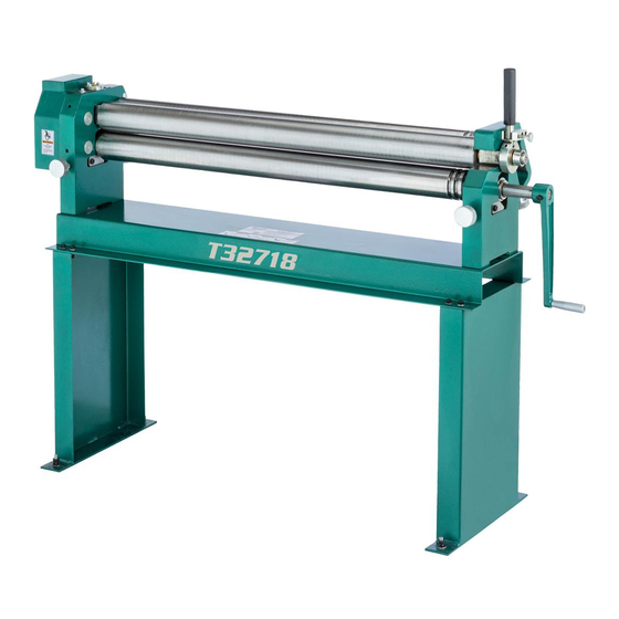
Figure 1. Main components. A. Rear Roller: Controls bend radius. B. Upper Roller: Secures presses workpiece against lower roller. C. Crank Handle: Turns lower roller, feeding workpiece through machine. D. Lower Roller: Feeds workpiece through machine. Model T32718 (Mfd. Since 07/21) -
Page 7: Machine Data Sheet
MACHINE DATA SHEET Customer Service #: (570) 546-9663 · To Order Call: (800) 523-4777 · Fax #: (800) 438-5901 MODEL T32718 41" SLIP ROLL Product Dimensions: Weight................................336 lbs. Width (side-to-side) x Depth (front-to-back) x Height............... 57-1/2 x 20-1/2 x 43 in. -
Page 8: Section 1: Safety
Never operate under the influence of drugs or injury or blindness from flying particles. Everyday alcohol, when tired, or when distracted. eyeglasses are NOT approved safety glasses. Model T32718 (Mfd. Since 07/21) - Page 9 Make sure they are properly installed, you experience difficulties performing the intend- undamaged, and working correctly BEFORE ed operation, stop using the machine! Contact our operating machine. Technical Support at (570) 546-9663. Model T32718 (Mfd. Since 07/21)
-
Page 10: Additional Safety For Slip Rolls
If normal safety pre- respect. Failure to do so could result in cautions are overlooked or ignored, seri- serious personal injury, damage to equip- ous personal injury may occur. ment, or poor work results. Model T32718 (Mfd. Since 07/21) -
Page 11: Section 2: Setup
Grizzly or the shipping agent. You MUST have the original pack- Box 1 (Figure 3) aging to file a freight claim. -
Page 12: Cleanup
Figure 4. T23692 Orange Power Degreaser. Repeat Steps 2–3 as necessary until clean, then coat all unpainted surfaces with a quality metal protectant to prevent rust. -10- Model T32718 (Mfd. Since 07/21) -
Page 13: Site Considerations
See below for required space allocation. Keep Area Unobstructed 20½" Keep Area Unobstructed 57½" Figure 5. Working clearances. -11- Model T32718 (Mfd. Since 07/21) -
Page 14: Assembly
With help from assistants, move slip roll off of pallet and onto crate top and orient it on its side so model number label faces up (see Figure 6). Figure 7. Lifting straps placed around and under rollers. -12- Model T32718 (Mfd. Since 07/21) -
Page 15: Anchoring To Floor
" — If load is unbalanced, immediately lower machine and reposition lifting straps as The Model T32718 is top heavy and may tip necessary. Repeat this step until you are as a result of the dynamic forces necessary for satisfied that load is safely balanced. -
Page 16: Section 3: Operations
Read books/magazines or get CW=Clockwise formal training before beginning any proj- CCW=Counterclockwise ects. Regardless of the content in this sec- tion, Grizzly Industrial will not be held liable for accidents caused by lack of training. -14- Model T32718 (Mfd. Since 07/21) -
Page 17: Flat Rolling
" below top roller (see Figure 11). Lower rear roller to lowest position (see Figure 11). Rear Roller Figure 13. Raising lower roller ⁄ turn. Lower Roller Figure 11. Slip roll preparation. -15- Model T32718 (Mfd. Since 07/21) -
Page 18: Creating Bends
Make sure no body part or clothing is near area between rollers. Failure to follow this warning may result in fingers, hair, or clothing being pulled into machine, causing personal injury. Figure 16. Raising lower roller. -16- Model T32718 (Mfd. Since 07/21) - Page 19 Failure to do so will cre- ate a larger radius on one end than the other, resulting in a cone or spiral shape. Figure 19. Feeding workpiece through machine. Figure 18. Setting bending radius. -17- Model T32718 (Mfd. Since 07/21)
-
Page 20: Creating Cylinders
⁄ Circumference " Figure 20. Example of calculating circumference and needed workpiece length. Once you have a workpiece the necessary length, Figure 22. Raising lower roller. follow the following steps to create the cylinder. -18- Model T32718 (Mfd. Since 07/21) - Page 21 Turn crank handle clockwise to feed workpiece through machine. Continue turning until workpiece is completely through upper and lower rollers (see Figure 24). Figure 26. Creating a cylinder. Figure 24. Feeding workpiece through machine. -19- Model T32718 (Mfd. Since 07/21)
- Page 22 — If ends of cylinder overlap, either attempt Figure 28. Upper roller release lever pulled to increase radius by manually bending down. it, or scrap workpiece and start at Step 1 with new workpiece. -20- Model T32718 (Mfd. Since 07/21)
-
Page 23: Creating Cones
SmallD=Small Diameter Large Circum. Figure 31. Example of known cone dimensions. The Model T32718 can bend cylinder and cone diameters as small as 3" due to the roller size, so both diameters of your cone must be larger than 3" to be bent on this machine. Since a "true" cone Small Circum. - Page 24 ConeH=Finished Cone Height " (see Figure 37). mately 6 ⁄ RadiusH ⁄ " ⁄ " Figure 35. Radius height of flat workpiece. Figure 37. Example of calculated radius height from known diameters and overall cone height. -22- Model T32718 (Mfd. Since 07/21)
- Page 25 TConeH=Finished True Cone Height LargeD LargeD=Large Diameter TConeH=ConeH x LargeD - SmallD TConeH=6 x 5 - 3 TConeH=6 x TConeH=6 x 2.5 TConeH=15 TConeRadiusH TConeH Figure 40. Location of finished and radius true cone heights. -23- Model T32718 (Mfd. Since 07/21)
- Page 26 TConeRadiusH (see Figure 41). Figure 43. Using string to draw outer circumference circle. TConeRadiusH x 2 TConeRadiusH x 2 Figure 41. Workpiece with required length and width. -24- Model T32718 (Mfd. Since 07/21)
- Page 27 Edge Line Figure 47. Straight line from center to large Figure 45. Straight line from center to outer circumference mark. circle. Measure and cut fresh piece of string or cord to length of LargeC. -25- Model T32718 (Mfd. Since 07/21)
- Page 28 12. Turn thickness adjustment knobs to adjust lower roller to approximately " below top roller (see Figure 49). Figure 50. Raising lower roller. -26- Model T32718 (Mfd. Since 07/21)
- Page 29 It is easy to decrease radius but very difficult to increase radius later. 18. Turn crank handle clockwise to feed workpiece through machine. Continue turning until workpiece is completely through upper and lower rollers. -27- Model T32718 (Mfd. Since 07/21)
- Page 30 (see Figure 56), remove workpiece from upper roller, then slide upper roller back into bracket. Upper Roller Upper Roller Bracket Figure 56. Upper roller released (workpiece already removed from roller for photo clarity). -28- Model T32718 (Mfd. Since 07/21)
-
Page 31: Using Wire Grooves To Bend Objects
Feed material through machine as described in Creating Bends on Page 16, Creating Cylinders on Page 18, or Creating Cones on Page 21, depending on your operation. Lower Roller Figure 58. Slip roll preparation. -29- Model T32718 (Mfd. Since 07/21) -
Page 32: Section 4: Accessories
To reduce this risk, only install accessories recommended for this machine by Grizzly. NOTICE Refer to our website or latest catalog for additional recommended accessories. -
Page 33: Section 5: Maintenance
To reduce risk of shock or accidental startup, always disconnect machine from power before adjustments, Cleaning the Model T32718 is relatively easy. maintenance, or service. Periodically wipe down the rollers to remove dust and debris—this ensures rust-promoting material does not remain on the bare metal surfaces. -
Page 34: Lubrication
65). Rotate the crank handle in both directions to distribute the grease to all the gears, then wipe away any excess and install the gear cover. Figure 67. Location of ball oiler. Gears (2 of 4) Figure 65. Location of roller gears. -32- Model T32718 (Mfd. Since 07/21) -
Page 35: Section 6: Service
Workpiece 1. Lower roller is not parallel to upper roller. 1. Adjust thickness adjustment knobs as necessary to does not feed align lower roller with upper roller. evenly through machine. -33- Model T32718 (Mfd. Since 07/21) -
Page 36: Section 7: Parts
SECTION 7: PARTS We do our best to stock replacement parts when possible, but we cannot guarantee that all parts shown are available for purchase. Call (800) 523-4777 or visit www.grizzly.com/parts to check for availability. Main BUY PARTS ONLINE AT GRIZZLY.COM! -34- Model T32718 (Mfd. - Page 37 REAR ROLLER BUSHING PT32718059 KEY 6 X 6 X 20 RE PT32718030 BALL BEARING 6005ZZ PT32718060 SET SCREW M8-1.25 X 10 BUY PARTS ONLINE AT GRIZZLY.COM! -35- Model T32718 (Mfd. Since 07/21) Scan QR code to visit our Parts Store.
-
Page 38: Labels & Cosmetics
Safety labels help reduce the risk of serious injury caused by machine hazards. If any label comes off or becomes unreadable, the owner of this machine MUST replace it in the original location before resuming operations. For replacements, contact (800) 523-4777 or www.grizzly.com. BUY PARTS ONLINE AT GRIZZLY.COM! -36- Model T32718 (Mfd. -
Page 39: Warranty & Returns
WARRANTY & RETURNS Grizzly Industrial, Inc. warrants every product it sells for a period of 1 year to the original purchaser from the date of purchase. This warranty does not apply to defects due directly or indirectly to misuse, abuse, negligence, accidents, repairs or alterations or lack of maintenance.
Need help?
Do you have a question about the T32718 and is the answer not in the manual?
Questions and answers