Table of Contents
Advertisement
Quick Links
EN
2
WAMGROUP S.p.A.
Via Cavour, 338
41030 Ponte Motta
Cavezzo (MO) - ITALY
VCP
Series R03
SPRING-LOADED PRESSURE
RELIEF VALVES
ASSEMBLY AND
MAIN INSTRUCTIONS
FOR USE AND
MAINTENANCE
Manual No. VAL.VCP.--.M.A5.1017.EN
Latest Update: October 2017
ORIGINAL INSTRUCTIONS IN ENGLISH
Issue: A5
+ 39 / 0535 / 618111
fax
+ 39 / 0535 / 618226
e-mail
info@wamgroup.com
internet
www.wamgroup.com
Advertisement
Table of Contents

Related Manuals for WAMGROUP VCP R03 Series


Summary of Contents for WAMGROUP VCP R03 Series
- Page 1 MAIN INSTRUCTIONS FOR USE AND MAINTENANCE Manual No. VAL.VCP.--.M.A5.1017.EN Issue: A5 Latest Update: October 2017 ORIGINAL INSTRUCTIONS IN ENGLISH WAMGROUP S.p.A. + 39 / 0535 / 618111 Via Cavour, 338 + 39 / 0535 / 618226 41030 Ponte Motta e-mail info@wamgroup.com...
- Page 2 All the products described in this catalogue are manufactured according to WAMGROUP S.p.A. Quality System procedures. The Company’s Quality System, certified in July 1994 according to International Standards UNI EN ISO 9002 and extended to the latest release of UNI EN ISO 9001, ensures that the entire production process, starting from the processing of the order to the technical service after delivery, is carried out in a controlled manner that guarantees the quality standard of the product.
-
Page 3: Table Of Contents
10.17 INDEX VAL.VCP.--.M.A5.1017.EN Issue: A5 SUMMARY 1.0 GENERAL INFORMATION ........................1 1.1 Scope of the Manual ......................... 1 1.2 Symbols ............................2 1.3 Glossary and terminology ......................... 4 1.4 Manufacturer’s data and identification of the valve ................5 1.5 Request for assistance ........................5 1.6 Warranty ............................ - Page 4 10.17 INDEX VAL.VCP.--.M.A5.1017.EN Issue: A5 6.0 INFORMATION REGARDING USE ....................... 32 6.1 Production Start-up ......................... 32 6.2 Shuttdown of the valve at the end of the work cycle ............... 32 6.3 Long shutdowns of the valve ......................33 6.4 Reuse .............................. 33 7.0 INFORMATION REGARDING MAINTENANCE ..................
-
Page 5: General Information
10.17 1.0 GENERAL INFORMATION VAL.VCP.--.M.A5.1017.EN Issue: A5 1.1 Scope of the Manual This Manual has been prepared by the Manufacturer to provide the operating technical information for instal- lation, operation and maintenance of the valve concerned. The Manual, which is an integral part of the valve concerned, must be preserved throughout the life of the valve in a known easily accessible place, available for consultation whenever required. -
Page 6: Symbols
10.17 1.0 GENERAL INFORMATION VAL.VCP.--.M.A5.1017.EN Issue: A5 1.2 Symbols To highlight certain parts of the text, for purposes of safety, or to indicate important information, certain symbols are used, the meaning of which is described below. It is important to comply with and scrupulously follow the information highlighted by the symbols. Danger - Warning Indicates situations of serious danger which, if ignored, can be risky for the health and safety of per- sons. - Page 7 10.17 1.0 GENERAL INFORMATION VAL.VCP.--.M.A5.1017.EN Issue: A5 List of safety and information symbols Symbol Symbol description representation Danger sign: indicates danger of electric shock caused by the presence of powered components inside the junction box or control panel. Obligation: read this Manual before carrying out any action on the valve concerned. Forbidden: indicates that it is forbidden to lubricate or adjust moving parts.
-
Page 8: Glossary And Terminology
10.17 1.0 GENERAL INFORMATION VAL.VCP.--.M.A5.1017.EN Issue: A5 1.3 Glossary and terminology Operator: person appropriately trained and authorized by the Production Manager for setting up the valve concerned and carrying out routine maintenance. Installer: organization with specialized technicians and appropriate equipment for carrying out risk-free instal- lation and extraordinary maintenance. -
Page 9: Manufacturer's Data And Identification Of The Valve
The ID plates shown identify the valve concerned and its main components. The plates show the reference necessary for operating safety. 1) Type of valve Year WAMGROUP 2) Serial No. 3) Code WAM S.p.A. via Cavour 338-Ponte Motta / Cavezzo (MO) - ITALY... -
Page 10: Exclusion Of Responsibility
10.17 1.0 GENERAL INFORMATION VAL.VCP.--.M.A5.1017.EN Issue: A5 1.7 Exclusion of responsibility The valve is delivered according to the specifications indicated by the Buyer in the order and the conditions valid at the time of purchase. The Manufacturer shall not accept responsibility for safety of persons or objects and operation failure of the valve if the loading/unloading operations from trucks, transport, positioning at the site, use, repairs, mainte- nance etc. -
Page 11: Information Regarding Safety
10.17 2.0 INFORMATION REGARDING SAFETY VAL.VCP.--.M.A5.1017.EN Issue: A5 2.1 General safety prescriptions Read the Instruction Manual carefully and strictly follow the instructions it includes, especially those regarding safety. Most accidents at the workplace are caused by negligence, failure to follow the most elementary safety regulations and incorrect or improper use of tools and equipment. -
Page 12: Safety Prescriptions For Installation
10.17 2.0 INFORMATION REGARDING SAFETY VAL.VCP.--.M.A5.1017.EN Issue: A5 2.3 Safety prescriptions for installation Before starting with installation, a “Safety Plan” must be implemented to safeguard the personnel di- rectly involved and those who carry out operations in the surrounding area. All the laws must be strictly applied, especially those concerning workplace safety. - Page 13 10.17 2.0 INFORMATION REGARDING SAFETY VAL.VCP.--.M.A5.1017.EN Issue: A5 Apart from invalidation of the warranty, the Manufacturer declines all responsibility for damage to objects and harm to persons deriving from the use of non-original spare parts or due to modifications made during repairs without express written authorization. Use the oil and lubricants recommended by the Manufacturer.
-
Page 14: Technical Information
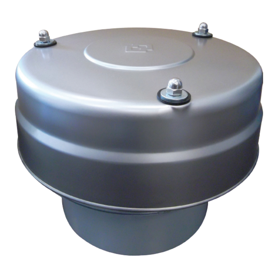
10.17 3.0 TECHNICAL INFORMATION VAL.VCP.--.M.A5.1017.EN Issue: A5 3.1 General description of the valve VCP Pressure Relief Valves consist of a cylindrical casing with a bottom flange to be connected with a spigot welded on the silo roof, a disc shape inner steel lid for negative pressure operation held in position by a cen- tral spring rod, an outside steel ring for excess pressure kept in position by three spring rods, gaskets, and a weather protection cover. -
Page 15: Operating Principle
10.17 3.0 TECHNICAL INFORMATION VAL.VCP.--.M.A5.1017.EN Issue: A5 3.3 Operating principle The Spring-Loaded Pressure Relief Valve are used in all plants where it is required to control excess pressures or negative pressures, if any, that may be created inside the containers, thereby preventing their breakage or deformation. -
Page 16: Improper Use Not Permitted
10.17 3.0 TECHNICAL INFORMATION VAL.VCP.--.M.A5.1017.EN Issue: A5 3.5 Improper use not permitted Danger - Warning Uses not permitted: the valve must be used only for the specific purpose envisaged by the Manufac- turer. Specifically: - do not use the valves if they have not been installed correctly in accordance with the standards in force. - do not use the valves if the gaskets are not intact. - Page 17 10.17 3.0 TECHNICAL INFORMATION VAL.VCP.--.M.A5.1017.EN Issue: A5 9) Every time the calibrated pressure value is exceeded, the valve will open and release an air-dust mixture (a dust cloud) to the outside, but only during the activation phase due to overpressure. The VCP valve is suit- able for use on pressurized or vacuum containers not subjected to special testing or legislation.
-
Page 18: Noise Level
10.17 3.0 TECHNICAL INFORMATION VAL.VCP.--.M.A5.1017.EN Issue: A5 3.6 Noise level The only source of noise on the valve is due to the air that passes through during operation. The VCP valve is usually installed on the top of silos, i.e. in places where exposure of operators is limited. Dur- ing maintenance, the plant must remain stationary, so there is no noise from the valve. -
Page 19: Safety And Information Signs
10.17 3.0 TECHNICAL INFORMATION VAL.VCP.--.M.A5.1017.EN Issue: A5 3.9 Safety and information signs Danger - Warning Follow the signs on the plates. The plates have to be readable; if they are not, clean them, replace the damaged ones and place them in their original position. -
Page 20: Information Regarding Handling And Transport
10.17 4.0 INFORMATION REGARDING HANDLING AND TRANSPORT VAL.VCP.--.M.A5.1017.EN Issue: A5 4.1 Type of packaging The type of packaging is selected according to the type of valve supplied, the transport means used, the quan- tity of goods shipped and the destination. To facilitate shipment, the valves may be divided into separate packages that are suitably protected. -
Page 21: Reception Of Goods
10.17 4.0 INFORMATION REGARDING HANDLING AND TRANSPORT VAL.VCP.--.M.A5.1017.EN Issue: A5 NOTE: The data given do not include the weight of a combined package (pallet or other). Packaging - Dimensions VCP type 2731C 2732C 3751C 3752C Single packaging included dimensions in mm Weld-on spigot for connection to silo included If parts made of plastic are present inside the package, do not burn these as they are contaminants. -
Page 22: Lifting And Unloading Methods
10.17 4.0 INFORMATION REGARDING HANDLING AND TRANSPORT VAL.VCP.--.M.A5.1017.EN Issue: A5 4.3 Lifting and unloading methods Danger - Warning Carry out the lifting and handling operations according to the information indicated on the valve and in the Manufacturer’s Operation Manual. The person authorized for unloading operations has to make sure all the necessary measures are adopt- ed to ensure his or her safety and the safety of other persons directly involved. -
Page 23: Installation And Fixing
10.17 5.0 INSTALLATION AND FIXING VAL.VCP.--.M.A5.1017.EN Issue: A5 5.1 Recommendations for installation, maintenance and cleaning Danger - Warning The installation operations have to be carried out by a technician specialised in such activities Provide appropriate safety measures and use suitable equipment to prevent risk of work accident to the persons involved in the operations and to those nearby. -
Page 24: Storage
10.17 5.0 INSTALLATION AND FIXING VAL.VCP.--.M.A5.1017.EN Issue: A5 5.2 Storage Storage prior to instal lation - Avoid damp and salty atmospheres as possible. - Position the valve on wooden platforms, or protected from unfavorable weather con ditions (do not stack). - Do not store the valve in the open or in areas where there are vapours or substances not compatible with the mate rial used to manufacture the valve (not even slightly corrosive substances). - Page 25 10.17 5.0 INSTALLATION AND FIXING VAL.VCP.--.M.A5.1017.EN Issue: A5 PRESSURE SETTING 273 VCP2731C - VCP2732C Excess Pressure Negative pressure Spring colour Spring colour mm H mm H Green 300 ± 100 Grey 50 ± 20 Grey 500 ± 100 Yellow 100 ± 30 800 ±...
- Page 26 10.17 5.0 INSTALLATION AND FIXING VAL.VCP.--.M.A5.1017.EN Issue: A5 EXCESS PRESSURE The package includes: A) Three springs which colours identify excess pressure to allow setting according to the following Table: Pressure Colour (mm H Green 300 ± 100 800 ± 200 Yellow -100 ±...
- Page 27 10.17 5.0 INSTALLATION AND FIXING VAL.VCP.--.M.A5.1017.EN Issue: A5 1) Remove the cap nuts and the three rubber gaskets on the upper part of the valve. 2) Remove the cap. 3) Remove the washers and rubber gaskets from the upper part of the three regulation units. Then unscrew the three nuts holding them in place.
- Page 28 10.17 5.0 INSTALLATION AND FIXING VAL.VCP.--.M.A5.1017.EN Issue: A5 NEGATIVE PRESSURE The package includes: A) One yellow spring for setting the valve opening negative pressure at -100mm H O (± 30 mm H B) One M12 x 130 UNI 5737 screw. C) Assembly instructions.
-
Page 29: Positioning The Valve
10.17 5.0 INSTALLATION AND FIXING VAL.VCP.--.M.A5.1017.EN Issue: A5 1) Remove the three cap nuts and the three rubber gaskets from the upper part of the valve. 2) Remove the cap. 3) Using two adjustable wrenches slacken the two bolts that block the negative pressure spring. 4) Position the valve on a surface as shown in the Figure. -
Page 30: Installation And Fixing Of The Valve
10.17 5.0 INSTALLATION AND FIXING VAL.VCP.--.M.A5.1017.EN Issue: A5 5.6 Installation and fixing of the valve - Lifting the valve Danger - Warning Carry out the lifting and handling operations according to the information shown on the valve and in the Manufacturer's Operation Manual. The specialist technician authorized for carrying out the installation must make sure all the necessary measures are adopted to ensure his own safety and that of other persons directly involved. - Page 31 10.17 5.0 INSTALLATION AND FIXING VAL.VCP.--.M.A5.1017.EN Issue: A5 INSTALLATION OF THE VALVE DIRECTLY ON THE SILO Prior to installation the valves for food applications (model GF) shall be subjected to cleaning and sanitation by means of a woven/non-woven cloth and sanitizer spray. 1) Make sure the surface on which the valve is to be fixed (container cover) is fixed horizontally.
-
Page 32: Electrical Connection
10.17 5.0 INSTALLATION AND FIXING VAL.VCP.--.M.A5.1017.EN Issue: A5 RE-ASSEMBLY Depending on the type of action carry out the operations described earlier in reverse order by paying special attention to: 1) Position the diaphragms correctly ensuring that their gaskets adhere to the relative supporting surface. 2) Place the springs and guide washers at the centre of the threaded adjustment rods. -
Page 33: Inductive Proximity Switch
10.17 5.0 INSTALLATION AND FIXING VAL.VCP.--.M.A5.1017.EN Issue: A5 5.8 Inductive proximity switch The VCP valve in all its sizes can be provided with an inductive signalling system. This device signals the opening of the valve in overpressure or negative pressure at the prefixed calibration value. -
Page 34: Compressed Air Connection
10.17 5.0 INSTALLATION AND FIXING VAL.VCP.--.M.A5.1017.EN Issue: A5 Description Type Nominal capacity 5 mm 2-wire type NC (protected against short circuits) XS1-M18MB250 Weight (kg) 0.120 Features cable 2x0.5 mm Type of connection length 2.0 m (1) Protection degree IP 68 Operating range 0...4 mm Repeatibility precision... -
Page 35: Inspection
10.17 5.0 INSTALLATION AND FIXING VAL.VCP.--.M.A5.1017.EN Issue: A5 5.10 Inspection Important When installation is complete, authorized personnel must carry out a general test to make sure the safety conditions have been complied with completely. The authorized personnel must also check: - That no tools or other material have been left inside the valve;... -
Page 36: Information Regarding Use
10.17 6.0 INFORMATION REGARDING USE VAL.VCP.--.M.A5.1017.EN Issue: A5 6.1 Production Start-up Before carrying out any operation set the valve in safety condition. - Start valve operation on empty. If the valve works correctly, add material and proceed with regular operation. Especially with materials which tend to harden or become sticky through longer periods of storage ensure no material or liquid is deposited on the shaft passages. -
Page 37: Long Shutdowns Of The Valve
10.17 6.0 INFORMATION REGARDING USE VAL.VCP.--.M.A5.1017.EN Issue: A5 6.3 Long shutdowns of the valve Possible reuse after long shutdowns Set the valve in safety condition before carrying out any operation. During valve shutdowns: 1) Avoid damp and salty atmos pheres. 2) Place the valve on wooden platforms, or protected from unfa vourable weather conditions. - Page 38 10.17 6.0 INFORMATION REGARDING USE VAL.VCP.--.M.A5.1017.EN Issue: A5 Important Failure to strictly follow the instructions can cause problems and invalidate the warranty on the valves supplied. PERIODIC INSPECTIONS REQUIRED Before any kind of operation, set the valve in safety condition. To avoid crusts formation, damages or clogging of the valves installed on silos, first clean them inside and then the surrounding area, taking care to avoid dust dispersal.
-
Page 39: Information Regarding Maintenance
10.17 7.0 INFORMATION REGARDING MAINTENANCE VAL.VCP.--.M.A5.1017.EN Issue: A5 7.1 Cleaning the valve Before carrying out any operation, set the valve in safety condition. While removing dust from the valve, avoid spreading it in the surrounding area. The user must use suitable clean ing materials depending on the type of plant and the material handled; avoid us ing toxic or inflammable materials. -
Page 40: Replacement Of Parts
10.17 8.0 REPLACEMENT OF PARTS VAL.VCP.--.M.A5.1017.EN Issue: A5 8.1 Safety recommendations for replacement Danger - Warning The replacement operations must be carried out by a specialist authorized technician with specific skills in the sector concerned (mechanical, electrical etc). Before carrying out any operation, provide suitable safety measures and use the appropriate equip- ment to prevent risk of work injuries to persons involved in the operations and those nearby. -
Page 41: Information Regarding Faults
10.17 9.0 INFORMATION REGARDING FAULTS VAL.VCP.--.M.A5.1017.EN Issue: A5 9.1 Trouble-shooting Minor problems can be solved without consulting a specialist. The following Table contains a list of the most common problems, the possible causes and possible remedies. For particularly difficult actions which are not mentioned in the Table, contact the Manufacturer’s Customer Service Department. - Page 42 10.17 9.0 INFORMATION REGARDING FAULTS VAL.VCP.--.M.A5.1017.EN Issue: A5 1) Information necessary a) Description of problem; b) Photo showing the entire valve and how it is installed; c) Valve type; d) Does the valve start up without any problem after long shutdowns? e) Is the outlet spout free of encrustations which could reduce the cross-section? f) Does the weather conditions have a negative influence on the operation of the valve? 2) Checking the silo...
-
Page 43: Technical Data
10.17 10.0 TECHNICAL DATA VAL.VCP.--.M.A5.1017.EN Issue: A5 FLOW RATE VCP 273 OVERPRESSURE GRAPH Flow rate VCP 273 with std. springs 7500 7000 6500 Calibration 300 mm H 6000 5500 Calibration 500 mm H 5000 4500 Calibration 800 mm H 4000 3500 3000 2500... -
Page 44: Aattachments
10.17 A ATTACHMENTS VAL.VCP.--.M.A5.1017.EN Issue: A5 A1 Nuts and bolts tightening torque Table Tightening torque [Nm] Thread diameter Resistance Class 8.8 Resistance Class 10.9 Resistance Class 12.9 13.0 16.0 23.0 32.0 39.0 46.0 64.0 77.0 80.0 110.0 135.0 125.0 180.0 215.0 195.0 275.0...
Need help?
Do you have a question about the VCP R03 Series and is the answer not in the manual?
Questions and answers