Table of Contents
Advertisement
Quick Links
EN
2
TOREX S.p.A.
Via Canaletto, 139/A
I-41030 S. Prospero s/S
(MO) - Italy
VM
PINCH VALVES
ASSEMBLY AND
MAIN INSTRUCTIONS
FOR USE AND
MAINTENANCE
Manual No. TOR.VM.--.M.A.0518.EN
Latest update: May 2018
ORIGINAL INSTRUCTIONS IN ENGLISH
Issue: A
+ 39 / 059 / 8080811
fax
+ 39 / 059 / 908204
e-mail
torex@torex.it
internet
www.torex.it
Advertisement
Table of Contents

Related Manuals for WAMGROUP TOREX VM Series


Summary of Contents for WAMGROUP TOREX VM Series
- Page 1 PINCH VALVES ASSEMBLY AND MAIN INSTRUCTIONS FOR USE AND MAINTENANCE Manual No. TOR.VM.--.M.A.0518.EN Issue: A Latest update: May 2018 ORIGINAL INSTRUCTIONS IN ENGLISH TOREX S.p.A. + 39 / 059 / 8080811 Via Canaletto, 139/A + 39 / 059 / 908204 I-41030 S.
- Page 2 All the products described in this catalogue are manufactured according to TOREX S.p.A. Quality System procedures. The Company’s Quality System, certified according to ISO 9001-2008 guarantees that the entire production process, from the customer’s order to the after sales service, can fulfil the product quality standard. This publication cancels and replaces any previous edition and revision.
-
Page 3: Table Of Contents
05.18 INDEX TOR.VM.--.M.A.0518.EN Issue: A SUMMARY 1.0 GENERAL INFORMATION ........................1 1.1 Scope of the Manual .........................1 1.2 Symbols ............................2 1.3 Glossary and terminology .........................3 1.4 Manufacturer’s data and identification of the valve................4 1.5 Request for assistance ........................4 1.6 Warranty ............................4 1.7 Exclusion of responsibility .........................5 2.0 INFORMATION REGARDING SAFETY ....................6 2.1 General safety prescriptions ......................6... - Page 4 05.18 INDEX TOR.VM.--.M.A.0518.EN Issue: A 7.0 INFORMATION REGARDING MAINTENANCE ..................21 7.1 Cleaning the valve ...........................21 8.0 REPLACEMENT OF PARTS ........................22 8.1 Safety recommendations for replacement ..................22 8.2 Assembling/Disassembling the pinch valves ...................23 8.3 Returning the valve .........................27 8.4 Dismantling and disposal ........................27 9.0 INFORMATION REGARDING FAULTS ....................28 9.1 Trouble-shooting ..........................28 9.2 Check-list in case of fault ........................29...
-
Page 5: General Information
05.18 1.0 GENERAL INFORMATION TOR.VM.--.M.A.0518.EN Issue: A 1.1 Scope of the Manual This Manual has been prepared by the Manufacturer to provide the operating technical information for instal- lation, operation and maintenance of the valve concerned. The Manual, which is an integral part of the valve concerned, must be preserved throughout the life of the valve in a known easily accessible place, available for consultation whenever required. -
Page 6: Symbols
05.18 1.0 GENERAL INFORMATION TOR.VM.--.M.A.0518.EN Issue: A 1.2 Symbols To highlight certain parts of the text, for purposes of safety, or to indicate important information, certain symbols are used, the meaning of which is described below. It is important to comply with and scrupulously follow the information highlighted by the symbols. Danger - Warning It indicates situations of serious danger which, if ignored, can seriously put to a risk the health and safety of persons. -
Page 7: Glossary And Terminology
05.18 1.0 GENERAL INFORMATION TOR.VM.--.M.A.0518.EN Issue: A 1.3 Glossary and terminology Operator: person appropriately trained and authorized by the Production Manager for setting up the valve concerned and carrying out routine maintenance. Installer: organization with specialized technicians and appropriate equipment for carrying out risk-free instal- lation and extraordinary maintenance. -
Page 8: Manufacturer's Data And Identification Of The Valve
If the ID plate is damaged or is no longer legible (even just one informative element on it) contact the Manufacturer for a new ID plate and replace it. Via Canaletto, 139/A MEMBER OF 41030 S.Prospero (MO) WAMGROUP ITALY +39/0598080811 TOREX SpA Year: 2018 Type: VM Operating pressure max 3.5 bar... -
Page 9: Exclusion Of Responsibility
05.18 1.0 GENERAL INFORMATION TOR.VM.--.M.A.0518.EN Issue: A 1.7 Exclusion of responsibility The valve is delivered according to the specifications indicated by the Buyer in the order and the conditions valid at the time of purchase. The Manufacturer shall not accept responsibility for safety of persons or objects and operation failure of the valve if the loading/unloading operations from trucks, transport, positioning at the site, use, repairs, mainte- nance etc. -
Page 10: Information Regarding Safety
05.18 2.0 INFORMATION REGARDING SAFETY TOR.VM.--.M.A.0518.EN Issue: A 2.1 General safety prescriptions Read the Instruction Manual carefully and strictly follow the instructions it includes, especially those regarding safety. Most accidents at the workplace are caused by negligence, failure to follow the most elementary safety regulations and incorrect or improper use of tools and equipment. -
Page 11: Safety Prescriptions For Installation
05.18 2.0 INFORMATION REGARDING SAFETY TOR.VM.--.M.A.0518.EN Issue: A 2.3 Safety prescriptions for installation Before starting with installation, a “Safety Plan” must be implemented to safeguard the personnel di- rectly involved and those who carry out operations in the surrounding area. All the laws must be strictly applied, especially those concerning workplace safety. -
Page 12: Safety Prescriptions For Maintenance And Replacement Of Components
05.18 2.0 INFORMATION REGARDING SAFETY TOR.VM.--.M.A.0518.EN Issue: A 2.5 Safety prescriptions for maintenance and replacement of components Danger - Warning Before carrying out any operation on the valve concerned, ensure it is switched off and disconnected from all mains and use suitable devices to prevent the possibility of the power sources being activated accidentally. -
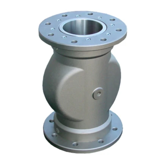
Page 13: Technical Information
05.18 3.0 TECHNICAL INFORMATION TOR.VM.--.M.A.0518.EN Issue: A 3.1 General description of the valve The VM valve opens or closes the passage of material through rubber sleeve that closes due to the action of the control pressure. The connection to the process occurs through the two flanges. 3.2 Main components Sizes and material Item... - Page 14 05.18 3.0 TECHNICAL INFORMATION TOR.VM.--.M.A.0518.EN Issue: A 3.2 Modular key code SLEEVE 0 Natural Rubber (Standard) 1 White Food Grade Natural Rubber Aluminium flange and bushings Aluminium flange and hardened bushings Aluminium flange and SS 304 bushings Flange (US standards) and aluminium bushings Aluminium threaded bushing Plastic threaded bushing SS304 threaded bushing...
- Page 15 05.18 3.0 TECHNICAL INFORMATION TOR.VM.--.M.A.0518.EN Issue: A 3.2.2 Accessories: Control Unit VMX The control unit VMX allows: - drive the opening / closing of the VM valve - adjust the control pressure - detect the presence of the control pressure on the valve Technical data and codes Control unit Operation...
-
Page 16: Operating Principle
05.18 3.0 TECHNICAL INFORMATION TOR.VM.--.M.A.0518.EN Issue: A 3.3 Operating principle Under normal operation conditions there is no compressed air inside the valve body; allowing, thus, the flowing of the material inside the valve. In the case of "stimulated” operation, compressed air is present inside the valve body and exerts pressure on the sleeve, allowing the closing of the valve and, as a consequence, prevents the flowing of the material. -
Page 17: Noise Level
05.18 3.0 TECHNICAL INFORMATION TOR.VM.--.M.A.0518.EN Issue: A 3.6 Noise level NOT APPLICABLE. 3.7 Environmental operating limits -0.5..+3.5 bar -10°C +80°C Tamb. -10°C +40°C max.6 bar Control pressure Pc Sleeve Size Pc (bar) Pc max (bar) Standard 13-200 Pi + 2.5 13-65 Pi + 2.5 White Food... -
Page 18: Overall Dimensions And Technical Features
05.18 3.0 TECHNICAL INFORMATION TOR.VM.--.M.A.0518.EN Issue: A 3.8 Overall dimensions and technical features Sizes de 40 - 200 Sizes de 40 - 100 Sizes de 13 - 32 Type VM013 1/2" VM020 3/4" VM025 1/8" 1" VM032 1+1/4" VM040 M 16 1+1/2"... -
Page 19: Safety And Information Signs
05.18 3.0 TECHNICAL INFORMATION TOR.VM.--.M.A.0518.EN Issue: A 3.9 Safety and information signs Danger - Warning Follow the signs on the plates. Ensure the plates are legible; otherwise clean them and replace the damaged ones, applying them in their original position. -
Page 20: Information Regarding Handling And Transport
05.18 4.0 INFORMATION REGARDING HANDLING AND TRANSPORT TOR.VM.--.M.A.0518.EN Issue: A 4.1 Type of packaging The VM Pinch valves are packed separately, in cardboard boxes. Depending on the quantity ordered, the boxes can be secured on pallets covered with film or shrink-wrap. The unpacking simply operations require the removal of the film (if present). -
Page 21: Reception Of Goods
05.18 4.0 INFORMATION REGARDING HANDLING AND TRANSPORT TOR.VM.--.M.A.0518.EN Issue: A 4.2 Reception of goods On receiving the goods, ensure that the type and quantity correspond to the data present on the acknowledge- ment of order. Possible damage has to be immediately communicated in writing in the space provided to this purpose in the waybill. -
Page 22: Installation And Fixing
05.18 5.0 INSTALLATION AND FIXING TOR.VM.--.M.A.0518.EN Issue: A 5.1 Safety prescriptions for installation Danger - Warning The replacement operations must be carried out by a specialist authorized technician with specific skills. Provide appropriate safety measures and use suitable equipment to prevent risk of work accident to persons involved in the operations and to those nearby. -
Page 23: Electrical Connection Of The Control Unit Vmx
05.18 5.0 INSTALLATION AND FIXING TOR.VM.--.M.A.0518.EN Issue: A 5.3 Electrical connection of the control unit VMX Item Description Pressure gauge Pressure regulator Monostable solenoid valve 3/2 1/8” N.A Pressure switch 1/8" 2.5 bar Solenoid valve... -
Page 24: Information Regarding Use
05.18 6.0 INFORMATION REGARDING USE TOR.VM.--.M.A.0518.EN Issue: A 6.1 Production start-up Important Set the equipment in safety condition before start-up. Before the final start-up of the valve, ensure the installation has been completely and properly carried out and that connections to external mains were made according to the following indications: - Read fully the INSTALLATION, USE AND MAINTENANCE manual. -
Page 25: Information Regarding Maintenance
05.18 7.0 INFORMATION REGARDING MAINTENANCE TOR.VM.--.M.A.0518.EN Issue: A Danger - Warning Before carrying out any maintenance activity, activate all the safety devices to ensure the safety of the persons involved in the operations and those nearby. Set the equipment concerned in safety condi- tion. -
Page 26: Replacement Of Parts
05.18 8.0 REPLACEMENT OF PARTS TOR.VM.--.M.A.0518.EN Issue: A 8.1 Safety recommendations for replacement Danger - Warning The replacement operations must be carried out by a specialist authorized technician with specific skills in the sector concerned (mechanical, electrical etc). Before carrying out any operation, provide suitable safety measures and use the appropriate equip- ment to prevent risk of work injuries to persons involved in the operations and those nearby. -
Page 27: Assembling/Disassembling The Pinch Valves
05.18 8.0 REPLACEMENT OF PARTS TOR.VM.--.M.A.0518.EN Issue: A 8.2 Assembling/disassembling the pinch valves ASSEMBLING 1) Prepare the components: body - bushings - flanges - sleeve. 2) Fit the sleeve inside the valve body. In case it doesn't slip in easily, grease the inner side of the body with silicone grease. - Page 28 05.18 8.0 REPLACEMENT OF PARTS TOR.VM.--.M.A.0518.EN Issue: A 3) Place a shim below the sleeve. 4) Make sure the sleeve protrudes from the upper edge of the body of a few millimetres (do not exceed 2 mm). 5) Lubricate the outer side of the bushing using only silicone grease.
- Page 29 05.18 8.0 REPLACEMENT OF PARTS TOR.VM.--.M.A.0518.EN Issue: A 7) Insert the flange in the bushing seat. Use two long screws positioned 180 degrees from each other as centring pins, so that the holes of the flange match the holes of the body, prevent the flange from rotating.
- Page 30 05.18 8.0 REPLACEMENT OF PARTS TOR.VM.--.M.A.0518.EN Issue: A DISASSEMBLY 1) Use an Allen key to unscrew the screws of the inlet flange. Once free, you can extract it manually. 2) Use two tools one opposite to the other to lever and remove the valve inlet bushing.
-
Page 31: Returning The Valve
05.18 8.0 REPLACEMENT OF PARTS TOR.VM.--.M.A.0518.EN Issue: A 8.3 Returning the valve When returning the valve use the original packaging if it has been preserved, otherwise fix the it on a pallet and cover it with nylon shrink-wrap, to protect it as best as possible from impact during transport. In any event, make sure there is no residue material inside the valve. -
Page 32: Information Regarding Faults
05.18 9.0 INFORMATION REGARDING FAULTS TOR.VM.--.M.A.0518.EN Issue: A 9.1 Trouble-shooting Minor problems can be solved without consulting a specialist. The following Table contains a list of the most common problems, the possible causes and possible remedies. For particularly difficult actions which are not mentioned in the Table, contact the Manufacturer’s Customer Service Department. -
Page 33: Check-List In Case Of Fault
05.18 9.0 INFORMATION REGARDING FAULTS TOR.VM.--.M.A.0518.EN Issue: A 9.2 Check-list in case of fault If you have been unable to solve the problem on the valve even after having carried out the operations sug- gested in paragraph “Trouble-shooting” please contact the plant technician/installer/or the Manufacturer. If technical assistance is required, in addition to the valve data, the plant technician/installer or Manufacturer will also need information concerning the plant in which the valve is installed, its installation and its working, for better identification of the problem that has occurred. -
Page 34: Spare Parts
05.18 10.0 SPARE PARTS TOR.VM.--.M.A.0518.EN Issue: A... - Page 35 05.18 10.0 SPARE PARTS TOR.VM.--.M.A.0518.EN Issue: A...
- Page 36 05.18 10.0 SPARE PARTS TOR.VM.--.M.A.0518.EN Issue: A CONFIGURATION A Description Codes Item Qty. EQUIPMENT SIZE VM040 VM050 VM065 VM080 VM100 Aluminium threaded bushing 20973551A 20973651A 20973751A 20973851A 20973951A SS 304 threaded bushing 20973552A 20973652A 20973752A 20973852A 20973952A Hardened threaded bushing 20973554A 20973654A 20973754A...
Need help?
Do you have a question about the TOREX VM Series and is the answer not in the manual?
Questions and answers