Table of Contents
Advertisement
Quick Links
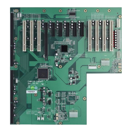
FAB118-14B5P7 Quick Installation Guide
Board Dimensions
©Copyright 2010 AXIOMTEK Co., Ltd.
4
Version A1 Dec 2010
Printed in Taiwan
9419B118010E
FAB118-14B5P7 Quick Installation Guide
I.
Checklist
FAB118-14B5P7 14-Slot ATX-Supported
PICMG 1.3 Bus Backplane x 1
Note1: Please contact your local vendors if any damaged or missing items.
DO NOT apply power to the board if any damaged components.
II.
Jumper List
Jumper
Open : ATX by CPU Card(default)
JP1
Short : ATX Power Always On
Auto Power Button (Optional)
JP2
Open : Disable
(Reserved)
Short : Enable
PCIEB1-PCIEB5 Link Speed(Gen1/Gen2)
JP3
Open : Auto (default)
Short(1-2)(3-4) : Gen1
III.
Connectors
Connector
CN1
ATX Power Connector
CN2
12V 8Pin(+12V Auxiliary Power Connector)
CN3
8-Pin Power Connector for thermal board
CN4
SM Bus Connector
CN5,CN6,CN7 (Reserved)
COM Ports and DIO Connector (Optional)
Thermal Sensor Connector for FAN1,FAN2 &
CN8,CN9,CN10,CN11(Reserved)
FAN3,FAN4(Optional)
CN12
PCIex16 SDVO Control Signal Connector
CN13
IPMB Connector
CN14
+3.3V/5V Auxiliary power Connector
CN15
+3.3V Auxiliary Power Connector
CN16
+5V Auxiliary Power Connector
USB1,USB2
USB 0,1,2,3 Connector
SATA1, SATA2(Reserved)
SATA1,2 Connector(Optional)
©Copyright 2010 AXIOMTEK Co., Ltd.
Version A1 Dec 2010
Printed in Taiwan
9419B118010E
Quick Installation Guide x 1
Description
Description
1
Advertisement
Table of Contents

Related Manuals for AXIOMTEK FAB118-14B5P7


Summary of Contents for AXIOMTEK FAB118-14B5P7
- Page 1 FAB118-14B5P7 Quick Installation Guide FAB118-14B5P7 Quick Installation Guide Board Dimensions Checklist FAB118-14B5P7 14-Slot ATX-Supported Quick Installation Guide x 1 PICMG 1.3 Bus Backplane x 1 Note1: Please contact your local vendors if any damaged or missing items. DO NOT apply power to the board if any damaged components.
- Page 2 FAB118-14B5P7 Quick Installation Guide FAB118-14B5P7 Quick Installation Guide Power ON/OFF Push Button Connector (PWRBT1) PWRBT1 ATX Power Button Connector Signal HWRST1 Hardware Reset Connector PWR_BT FAN1,FAN2,FAN3,FAN4 FAN Connector SHB1-SHB4 PICMG 1.3 Full-Size SBC Slot PPCI1-PPCI3;SPCI1-SPCI4 PCI Slots 32-bit/33MHz Hardware Reset Connector (HWRST1)
Need help?
Do you have a question about the FAB118-14B5P7 and is the answer not in the manual?
Questions and answers