
Related Manuals for Gliderol Roll.in.One


Summary of Contents for Gliderol Roll.in.One
- Page 1 Roll.in.One Automatic Roller Door Opener Installation Instructions and Roll.in.One Owner’s Manual...
-
Page 2: Safety Instructions
⚫ The Roll.in.One Operator has an electronic obstruction system that provides safe and reliable operation. It is however a legal requirement in some countries to also install a Photo-electric sensor across the door way, please check this requirement with your local distributor. -
Page 3: Installation Instructions
Installation Instructions The Roll.in.One unit may be retrofitted to any roller doors including non Gliderol doors and also it does not require any disassembly of the door during installation. The Roll.in.One unit may be retrofitted to either side of a roller door. Selection of the desired side may be determined by the available room, location of power and general installation. - Page 4 Make sure the door supporting prop is secure. While the door is supported remove the right hand wall mount bracket.(Fig. 3) f) Slide the Roll.in.One unit on to the spindle of the door. Fig: 3 g) Locate the engaging fork on the drive unit with drum wheel spoke. Please ensure the unit forks are fully engaged into the spoke of the drum wheel.
- Page 5 Alternate Method: On smaller size doors the Roll.in.One unit may be installed without removing and replacing the bracket. After step (d) carefully lift the roller door from the bracket enabling Roll.in.One unit to slide on to the spindle of the door. Ensuring the unit’s fork is properly engaged with the spoke of drum wheel carefully rest the door on the spindle and follow consecutive steps from (j).
- Page 6 IMPORTANT: Security rivet / tek screw must always be applied to inner side of drum wheel as shown in Fig: 7a. Failure to do so may result in internal damage to the Roll.in.One drive unit. ROLL.in.One Installation Instructions & Owner’s Manual...
- Page 7 Buzzer User Interface Transmitter Learn LED Function Select LED Transmitter Key Setting LED Auto Close Setting LED Photo Sensor Switch Connector Limit Setting LED Force Setting LED Courtesy Light LED Fig: 9 ROLL.in.One Installation Instructions & Owner’s Manual Page 7...
- Page 8 1. Press and hold [S], release finger while the red light turns from [F] to [K] 2. Press [S] again, when the light of [SEL/ADJ] turns RED or GREEN: RED indicates 3 button operation GREEN indicates single button operation ROLL.in.One Installation Instructions & Owner’s Manual Page 8...
- Page 9 4. Proceed to setup the TOP limit, by pressing [OPEN] button on transmitter, and confirm TOP limit position by pressing [STOP] button. 2 beeps will signal for successful programming. **While setting the TOP limit the [SEL/ADJ] light will turn green and starts blink. ROLL.in.One Installation Instructions & Owner’s Manual Page 9...
- Page 10 If for some reason the door has to be left opened for longer period, press the stop button before the door reaches the fully open position by this the Auto close function will not be activated. ROLL.in.One Installation Instructions & Owner’s Manual Page 10...
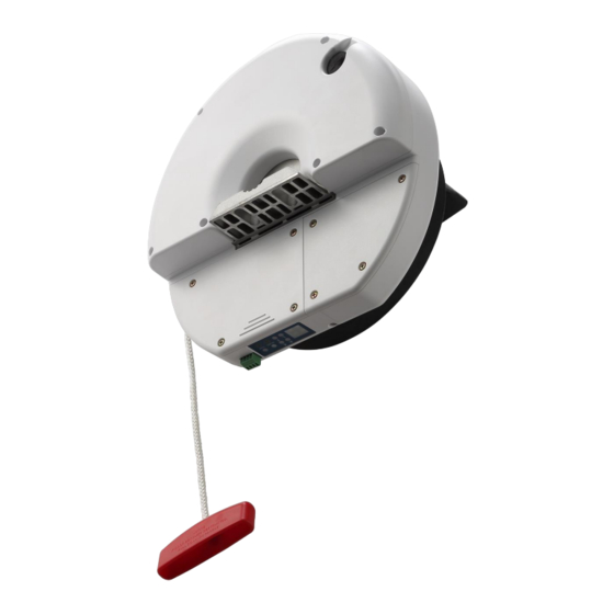
- Page 11 2. Replace the old batteries with new ones (3V CR2016x2) and ensure plastic strip remain intact in clip. Locate back of case and secure with screw. 10.0 Photo Sensor Connection Diagram GND-Black COM-Brown N,C-Yellow N,O-White 12V-Red ROLL.in.One Installation Instructions & Owner’s Manual Page 11...
- Page 12 Owner’s Manual for the Roll.in.One Automatic Roller Door Operator CONGRATULATIONS! On the purchase of your Roll.in.One Automatic Roller Door Opener INDEX Page Page Door Operation Key Ring Handset Manual Operation Wireless Wall Button Switch Obstruction Detection Photo Electric Sensor Vacation Mode...
-
Page 13: Troubleshooting
Trouble Shooting Before you call your local Gliderol agent please check the following Fault Table SYMPTOM ACTION Check electrical supply to unit. 1. Door does not operate. Press handset and/or bell press button again. Manual release may be engaged, pull the manual release chord 2. -
Page 14: Technical Specifications
Modulation Handset Deviation Handset RF Output Power Handset Transmitter Battery Handset Demodulation Mode Receiver Sensitivity ‐90 ‐100 Data Rate ℃ Operation Temperature ‐20 Output Voltage in circuit board terminal (0.5 amps Max) ROLL.in.One Installation Instructions & Owner’s Manual Page 14... -
Page 15: Warranty Form
NOTE: THIS FORM MUST BE COMPLETED BY THE INSTALLER AND PRODUCED AS PROOF OF PURCHASE DATE WHEN MAKING A SERVICE CALL UNDER WARRANTY, OTHERWISE SUCH CALLS ARE LIABLE TO SERVICE CHARGES. FOR SALES AND SERVICE, CONTACT Gliderol Garage Doors Head Office Gliderol Garage Doors Kitching Road, North West Industrial Estate, Peterlee, Co.
Need help?
Do you have a question about the Roll.in.One and is the answer not in the manual?
Questions and answers