Samson 2357-3 Mounting And Operating Instructions
Pressure build-up regulator
Hide thumbs
Also See for 2357-3:
- Mounting and operating instructions (12 pages) ,
- Mounting and operating instructions (40 pages)
Table of Contents
Advertisement
Quick Links
EB 2559 EN
Translation of original instructions
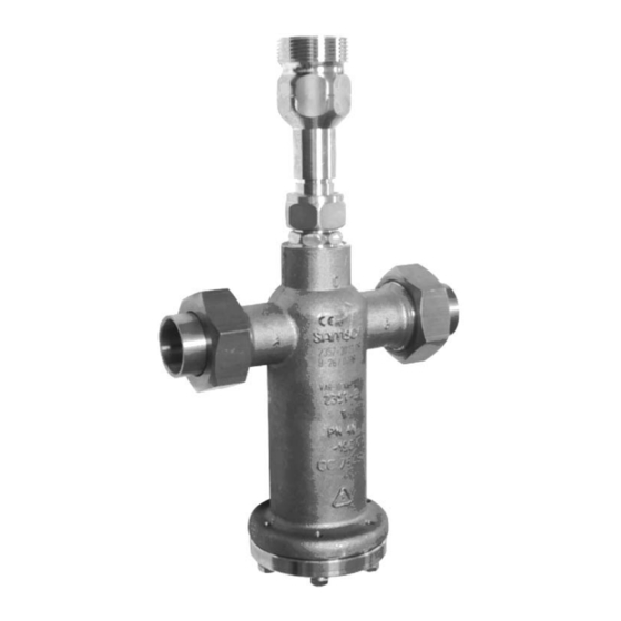
Type 2357-3 with non-return unit at Port C
Type 2357-3 made of CrNi steel
Ports A and B with solder nipple with ball-type bushing
(special version)
Type 2357-3 Pressure Build-up Regulator
Self-operated Pressure Regulators · Cryogenic
Edition April 2022
Advertisement
Table of Contents

Related Manuals for Samson 2357-3


Summary of Contents for Samson 2357-3
- Page 1 EB 2559 EN Translation of original instructions Type 2357-3 with non-return unit at Port C Type 2357-3 made of CrNi steel Ports A and B with solder nipple with ball-type bushing (special version) Type 2357-3 Pressure Build-up Regulator Self-operated Pressure Regulators · Cryogenic...
- Page 2 Note on these mounting and operating instructions These mounting and operating instructions assist you in mounting and operating the device safely. The instructions are binding for handling SAMSON devices. The images shown in these instructions are for illustration purposes only. The actual product may vary.
-
Page 3: Table Of Contents
Contents Safety instructions and measures ..............1-1 Notes on possible severe personal injury ............1-4 Notes on possible personal injury ..............1-5 Notes on possible property damage .............1-6 Markings on the device ................2-1 Nameplate ....................2-1 Material identification number ..............2-1 Design and principle of operation ...............3-1 Additional fittings ..................3-3 Technical data ....................3-4 Shipment and on-site transport ..............4-1... - Page 4 Decommissioning ..................10-1 Removal ....................11-1 11.1 Removing the regulator from the pipeline ............11-1 11.2 Removing the actuator from the valve ............11-1 Repairs ....................12-1 12.1 Returning devices to SAMSON ..............12-1 Disposal ....................13-1 Certificates ....................14-1 Annex......................15-1 15.1 Tightening torques ..................15-1 15.2 Lubricant ....................15-2 15.3...
-
Page 5: Safety Instructions And Measures
In case operators intend to use the regulators in applications or condi- tions other than those specified, contact SAMSON. SAMSON does not assume any liability for damage resulting from the failure to use the de- vice for its intended purpose or for damage caused by external forces or any other external factors. - Page 6 Safety instructions and measures Safety features The Type 2357-3 Regulator does not have any special safety features. When relieved of pressure, the regulator is opened by the force of the set point springs. Personal protective equipment We recommend checking the hazards posed by the process medium being used (e.g.
- Page 7 Start-up and shutdown procedures fall within the scope of the operator's duties and, as such, are not part of these mounting and operating instructions. SAMSON is unable to make any statements about these procedures since the operative details (e.g. differential pressures and temperatures) vary in each individual case and are only known to the operator.
-
Page 8: Notes On Possible Severe Personal Injury
Safety instructions and measures Referenced documentation The following documents apply in addition to these mounting and operating instructions: − Manuals e.g. Oxygen manual u H 01 − Data sheets for Spare parts and accessories · Self-operated regulators for e.g. u T 2570 cryogenic media −... -
Page 9: Notes On Possible Personal Injury
WARNING Damage to health relating to the REACH regulation. If a SAMSON device contains a substance which is listed as being a substance of very high concern on the candidate list of the REACH regulation, this circumstance is indi- cated on the SAMSON delivery note. -
Page 10: Notes On Possible Property Damage
Certain tools are required to work on the regulator. Î Only use tools approved by SAMSON. When in doubt, consult SAMSON. Note SAMSON's After-sales Service can support you concerning lubricant, tightening torques and tools approved by SAMSON. EB 2559 EN... -
Page 11: Markings On The Device
Customer-specific details CE/EAC marking Marking for special version with reinforced closing spring for use in the liquid phase Fig. 2-1: Nameplate of Type 2357-3 2.2 Material identification number Specifying the material number, you can contact us to find out which material is used. - Page 12 EB 2559 EN...
-
Page 13: Design And Principle Of Operation
Design and principle of operation 3 Design and principle of oper- duced by this pressure opposes the adjust- able spring force of the set point spring (8) ation and opens the tubular plug (2.2) when the Î See Fig. 3-1 pressure rises above the set point by approx. 0.5 bar. - Page 14 Body cover Set point adjuster (hex socket, SW 5) 11 Lock nut (SW 17) 12 Non-return unit (accessories) 13 Filter 14 Body screws 16 Closing spring Coupling nut for solder nipple with ball-type bushing (accessories) Fig. 3-1: Functional diagram of Type 2357-3 EB 2559 EN...
-
Page 15: Additional Fittings
Shut-off valves Pressure protection by Non-return unit Type 2357-3 with special Pressure build-up vaporizer accessories Type 2371-1 or Type 2371-11 Final vaporizer Pressure Reducing Valve Fig. 3-2: Schematic drawing of Series 2357-3 Pressure Build-up Regulator with safety function for cryogenic service EB 2559 EN... -
Page 16: Technical Data
Note The Type 2357-3 Regulator is not a safety The regulator functions as a pressure build- valve. If necessary, a suitable overpressure up regulator with safety function (direction of... - Page 17 Design and principle of operation Noise emissions Dimensions and weights SAMSON is unable to make general state- Table 3-1 provides a summary of the ments about noise emissions. The noise emis- weights. The lengths, heights and other di- sions depend on the regulator version, plant mensions in the dimensional drawings are facilities and process medium.
- Page 18 Design and principle of operation Table 3-1: Technical data · All pressures in bar (gauge) 2357-3 2357-3 Type – Process medium in the gas – Special version in the liquid phase – phase – Pressure rating PN 40 coefficient Set point range 2 to 10 bar ·...
- Page 19 Design and principle of operation Dimensions (in mm) Ø 80 Type 2357-3 · Standard version with solder nipple (accessories) and non-return unit (accessories) Fig. 3-3: Dimensions of the standard version EB 2559 EN...
- Page 20 Design and principle of operation Dimensions (in mm) Weld seam performed on site M40 x 2 Ø28 Ø80 Type 2357-3 · CrNi steel version with welding ends (accessories) and non-return unit (accessories) Fig. 3-4: Dimensions of the CrNi steel version EB 2559 EN...
-
Page 21: Shipment And On-Site Transport
2. Check the shipment for transportation 4.3 Transporting and lifting the damage. Report any damage to regulator SAMSON and the forwarding agent (refer to delivery note). Due to the low service weight, lifting equip- ment is not required to lift and transport the Note regulator (e.g. -
Page 22: Storing The Regulator
Î Observe the storage instructions. quest. Î Avoid long storage times. Î Contact SAMSON in case of different storage conditions or longer storage times. Storage instructions Î Protect the regulator against external in- fluences (e.g. -
Page 23: Installation
Installation 5 Installation 5.1 Installation conditions The work described in this section is only to Work position be performed by personnel appropriately The work position for the regulator is the qualified to carry out such tasks. front view onto all operating controls on the regulator (including any additional fittings) WARNING seen from the position of operating person-... - Page 24 Installation Mounting position Î Install the regulator with the actuator Standard mounting housing suspended downward (with port position C facing upward) in horizontal pipelines For gases, liquids and (see Fig. 5-1). steam Î Make sure the correct direction of flow is used for the body design and the intend- ed use.
-
Page 25: Preparation For Installation
Installation 5.2 Preparation for installation 5.3 Installation Before mounting, make sure the following The SAMSON regulator is an assembled unit conditions are met: in the delivered state. The activities listed be- low are necessary for installation and before − The regulator is clean. -
Page 26: Installing The Regulator
Installation 5.3.1 Installing the regulator 5.4 Testing the regulator 1. Close the shut-off valves (6.1 and 6.2) in DANGER the pipeline while the valve is being in- stalled. Risk of bursting due to incorrect opening of pressurized equipment or components. 2. -
Page 27: Leak Test
Î Wear protective clothing and safety tion. gloves. SAMSON regulators are delivered ready for SAMSON's After-sales Service can support use. To test the regulator functioning before you to plan and perform a leak test for your start-up or putting back the regulator into plant. -
Page 28: Pressure Test
Installation 5.4.2 Pressure test Note The plant operator is responsible for performing the pressure test. SAMSON's After-sales Service can support you to plan and perform a pressure test for your plant. NOTICE Risk of regulator damage due to a sudden pressure increase and resulting high flow velocities. -
Page 29: Start-Up
Start-up 6 Start-up WARNING The work described in this section is only to Risk of personal injury due to pressurized be performed by personnel appropriately components and process medium being dis- qualified to carry out such tasks. charged. Î Do not loosen the control line while the valve is pressurized. -
Page 30: Start-Up And Putting The Device Back Into Operation
Start-up 6.1 Start-up and putting the 6.2 Starting up the plant device back into operation 1. Start up the regulator after mounting all parts. 1. Depending on the field of application, allow the regulator to cool down or 2. Open the shut-off valves slowly prefera- warm up to reach ambient temperature bly starting from the upstream pressure before start up. -
Page 31: Operation
Operation 7 Operation 7.1 Adjusting the set point Immediately after completing start-up or Every regulator is delivered with the set point placing the regulator back into service (see listed in Table 7-3 already adjusted. the 'Start-up' section), the regulator is ready Turn the set point adjuster (10) using Allen for use. - Page 32 Operation Set point in bar Set point range 25 to 40 bar Set point range 8 to 26 bar Set point range 2 to 10 bar Turns of the set point adjuster Fig. 7-2: Adjustment diagram Table 7-3: Set point adjustment Set point range 2 to 10 bar 8 to 26 bar 25 to 40 bar...
-
Page 33: Malfunctions
After the pressure set point in the tank is reached, reopen the shut-off valves. Note Contact SAMSON's After-sales Service for malfunctions not listed in the table. EB 2559 EN... -
Page 34: Emergency Action
3. Rectify those malfunctions that can be remedied based on the instructions SAMSON's After-sales Service can support provided here. Contact SAMSON's you in drawing up an inspection and test After-sales Service in all other cases. -
Page 35: Servicing
Servicing 9 Servicing WARNING The regulator does not require any mainte- Explosion hazard due to the use of oil and nance. Nevertheless, it is subject to natural grease in oxygen atmospheres! wear, particularly at the seat, plug and oper- Make sure that the regulator is absolutely ating bellows. - Page 36 (see 'Tightening torques' in Annex). NOTICE Risk of regulator damage due to the use of unsuitable tools. Î Only use tools approved by SAMSON (see 'Tools' in Annex). Note The regulator was checked by SAMSON before it left the factory.
- Page 37 Body cover Set point adjuster (hex socket, SW 5) 11 Lock nut (SW 17) 12 Non-return unit (accessories) 13 Filter 14 Body screws 16 Closing spring Coupling nut for solder nipple with ball-type bushing (accessories) Fig. 9-1: Functional diagram of Type 2357-3 EB 2559 EN...
-
Page 38: Preparing The Valve For Service Work
The following service work can be per- formed after preparation is completed: Note − Replace the set point spring (see sec- SAMSON's After-sales Service can support tion 9.4) you concerning lubricant, tightening torques and tools approved by SAMSON. 9.2 Installing the regulator... - Page 39 Servicing Removing the set point spring Mounting the set point spring 1. Put the regulator out of operation (see 1. Insert new set point spring (8) for the re- the 'Decommissioning' section). quired set point range together with the operating bellows (3) into the valve body 2.
-
Page 40: Ordering Spare Parts And Operating Supplies
Servicing 9.5 Ordering spare parts and operating supplies Contact your nearest SAMSON subsidiary or SAMSON's After-sales Service for infor- mation on spare parts, lubricants and tools. Spare parts See Annex for details on spare parts. Lubricant Contact SAMSON's After-sales Service for more information on lubricants. -
Page 41: Decommissioning
Decommissioning 10 Decommissioning WARNING The work described in this section is only to Risk of personal injury due to pressurized be performed by personnel appropriately components and process medium being qualified to carry out such tasks. discharged. Î Do not loosen the external control line while the valve is pressurized. - Page 42 Decommissioning To decommission the regulator for service work or disassembly, proceed as follows: 1. Close the shut-off valve (6.1) on the up- stream side of the regulator. 2. Close the shut-off valve (6.2) on the downstream side of the regulator. 3.
-
Page 43: Removal
Removal 11 Removal 11.1 Removing the regulator from the pipeline The work described in this section is only to be performed by personnel appropriately 1. Support the regulator to hold it in place qualified to carry out such tasks. when separated from the pipeline (see the 'Shipment and on-site transport' sec- WARNING tion). - Page 44 11-2 EB 2559 EN...
-
Page 45: Repairs
Defective devices can be returned to does not function at all, it is defective and SAMSON for repair. Proceed as follows to must be repaired or exchanged. return devices to SAMSON: 1. Put the regulator out of operation (see... - Page 46 12-2 EB 2559 EN...
-
Page 47: Disposal
Disposal 13 Disposal Î Observe local, national and internation- al refuse regulations. Î Do not dispose of components, lubricants and hazardous substances together with your household waste. EB 2559 EN 13-1... - Page 48 13-2 EB 2559 EN...
-
Page 49: Certificates
Certificates 14 Certificates The EU declarations of conformity are in- cluded on the next pages: − EU declaration of conformity in compliance with Pressure Equipment Directive 2014/68/EU on page 14-2. − EU-type examination according to Directive 2014/68/EC, see page 14-3. − Additional manufacturer's declarations, see page 14-4 ff. - Page 50 Certificates 14-2 EB 2559 EN...
- Page 51 EU-Baumusterprüfung (Baumuster) Prüfbericht-Nr.: 968/FSP 2402.01/22 Beschreibung des Baumusters: Sicherheitsdruckregler ohne Hilfenergie als Ausrüstungsteil mit Sicherheitsfunktion Typ: 2357-1, 2357-2, 2357-3, 2357-11, 2357-21 Fertigungsstätte/Lieferer: Samson AG Weismüllerstraße 3 60315 Frankfurt Gültig bis: 03/32 Dieses Zertifikat verliert seine Gültigkeit, wenn das Produkt in irgendeiner Weise geändert oder modifiziert wird.
- Page 52 Translation of original document For the following products Type 2357 Pressure Regulator Versions for oxygen service according to SAMSON company standard WN 1.34-2, sheets 1 and 1.1 (Q-7004) We hereby confirm that all oxygen-wetted parts of the above mentioned regulators are cleaned, tested and assembled according to our qualified cleaning procedure.
- Page 53 Pressure Build-up Regulator with safety function and integrated pressure relief valve The combined Type 2357-3 Pressure Build-up Regulator is suitable for the use with liquefied cryogenic gases as well as flammable gases. The medium is sealed from the atmosphere by a metal bellows.
- Page 54 14-6 EB 2559 EN...
-
Page 55: Annex
Annex 15 Annex 15.1 Tightening torques Table 15-1: Tightening torque Position Part Tightening torque in Nm Width across flats Coupling nut SW 32 Screw plug SW 26 Screws SW 10 Coupling nut for solder nipple with ball-type bushing SW 49 (accessories) EB 2559 EN 15-1... -
Page 56: Lubricant
15.3 Tools You can reach our after-sales service at aftersalesservice@samsongroup.com. SAMSON's After-sales Service can support you concerning tools approved by Addresses of SAMSON AG and its subsid- SAMSON. iaries The addresses of SAMSON, its subsidiaries, 15.4 Spare parts representatives and service facilities... - Page 60 EB 2559 EN SAMSON AKTIENGESELLSCHAFT Weismüllerstraße 3 · 60314 Frankfurt am Main, Germany Phone: +49 69 4009-0 · Fax: +49 69 4009-1507 samson@samsongroup.com · www.samsongroup.com...
Need help?
Do you have a question about the 2357-3 and is the answer not in the manual?
Questions and answers