Samson 3277 Mounting And Operating Instructions
Pneumatic actuator
Hide thumbs
Also See for 3277:
- Mounting and operating instructions (12 pages) ,
- Quick manual (2 pages) ,
- Mounting and operating instruction (112 pages)

Related Manuals for Samson 3277


Summary of Contents for Samson 3277
- Page 1 Type 3271 and Type 3277 Pneumatic Actuators Actuator area: 175 and 750 cm² Type 3271 (left) and Type 3277 (right) Pneumatic Actuators Mounting and Operating Instructions EB 8310-5 EN Edition January 2017...
- Page 2 Î For the safe and proper use of these instructions, read them carefully and keep them for later reference. Î If you have any questions about these instructions, contact SAMSON‘s After-sales Service Department (aftersalesservice@samson.de). The mounting and operating instructions for the devices are included in the scope of delivery.
-
Page 3: Table Of Contents
Notes on possible personal injury ..............7 Notes on possible property damage ..............8 Markings on the device ................10 Actuator nameplate ..................10 Design and principle of operation ..............11 Type 3271 ....................11 Type 3277 ....................12 Direction of action ..................12 Signal pressure routing .................12 3.4.1 Type 3271 ....................12 3.4.2 Type 3277 ....................12... - Page 4 Contents Operation ....................26 Throttling service ..................26 On/off service .....................26 Manual mode ....................26 Additional notes concerning operation ............27 Reversal of the direction of action ..............27 6.5.1 Reversal of the direction of action from stem extends to stem retracts ....27 6.5.2 Reversal of the direction of action from stem retracts to stem extends ....30 Version with handwheel ................31 6.6.1 Extending the actuator stem manually ............32...
-
Page 5: Safety Instructions And Measures
SAMSON. SAMSON does not assume any liability for damage resulting from the failure to use the valve for its intended purpose or for damage caused by external forces or any other external factors. - Page 6 Î Check with the plant operator for details on further protective equipment. Revisions and other modifications Revisions, conversions or other modifications to the product are not authorized by SAMSON. They are performed at the user's own risk and may lead to safety hazards, for example. Fur- thermore, the product may no longer meet the requirements for its intended use.
-
Page 7: Notes On Possible Severe Personal Injury
Safety instructions and measures Referenced standards and regulations According to the ignition risk assessment performed in accordance with EN 13463-1:2009, section 5.2, the non-electrical actuators do not have their own potential ignition source even in the rare incident of an operating fault. As a result, they do not fall within the scope of Di- rective 2014/34/EU. -
Page 8: Notes On Possible Property Damage
(see section 9.3). Damage to health relating to the REACH regulation. If a SAMSON device contains a substance which is listed as being a substance of very high concern on the candidate list of the REACH regulation, this circumstance is indicat- ed on the SAMSON delivery note. - Page 9 Risk of actuator damage due to the use of unsuitable tools. Certain tools are required to work on the actuator. Î Only use tools approved by SAMSON (u AB 0100). Risk of actuator damage due to the use of unsuitable lubricants. The lubricants to be used depend on the actuator material. Unsuitable lubricants may corrode and damage the valve surface.
-
Page 10: Markings On The Device
12 Symbol indicating fail-safe action Actuator stem extends (FA) Actuator stem retracts (FE) Manual override 14 Connecting thread 15 Diaphragm material 16 Date of manufacture Made in Germany SAMSON 3271 Var-ID Serial no. Fig. 1: Nameplate of Type 3271 Actuator EB 8310-5 EN... -
Page 11: Design And Principle Of Operation
The bench range is determined by the ation number of springs used and their compres- The SAMSON Type 3271 and Type 3277 sion, taking into account the rated travel. The Actuators with 175 and 750 cm² actuator travel is proportional to the signal pressure areas are mounted to Series 240, 250, 280, . -
Page 12: Type 3277
3.4 Signal pressure routing The principle of operation is the same as that 3.4.1 Type 3271 of the Type 3271 Actuator. The Type 3277 Actuator is fitted with an additional yoke on In the "actuator stem extends" version, the the bottom diaphragm case (A2) (see Fig. 3). - Page 13 Design and principle of operation A26/27 Top diaphragm case Spring Bottom diaphragm Vent plug case A26/27 Stem connector Diaphragm clamp Diaphragm plate Signal pressure connection Actuator stem Ring nut Fig. 3: Functional diagram of Type 3277 Actuator (750 cm²), "stem retracts" direction of action EB 8310-5 EN...
-
Page 14: Fail-Safe Action
Design and principle of operation 3.5 Fail-safe action 3.6 Versions When the signal pressure is reduced or the Type 3271 and Type 3277 Pneumatic Actua- control signal fails, the fail-safe position of tor (175 and 750 cm²): the control valve depends on whether the −... - Page 15 (accessories). Item no. Compliance Actuator Eyebolt Swivel lifting area The Type 3271 and Type 3277 Pneumatic (DIN 580) hook Actuators bear the EAC mark of conformity. 750 cm² 8325-0131 8442-1017 Actuators with 175 cm² actuator area or smaller do not require a female thread or...
- Page 16 Design and principle of operation Table 1: Dimensions in mm and weights in kg Actuator Type 3271 3277 Actuator area cm² rated Height – – – – 1) 1) Travel limitation ØD Diameter ØD2 Ød (thread) M30x1.5 2) G ¼ (¼ NPT) G ...
- Page 17 Design and principle of operation Dimensional drawings ØD ØD1 ØD2 Ød Type 3277 with 750 cm² actuator area ØD2 Ød ØD Type 3271 with travel stop Type 3277 (750 cm²) with handwheel EB 8310-5 EN...
-
Page 18: Measures For Preparation
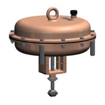
2. Check the shipment for transportation attached slings. damage. Report any damage to − 750 cm² version: the lifting eyelet on the SAMSON and the forwarding agent top diaphragm case is intended for mount- (refer to delivery note). ing and removing the actuator as well as lifting the actuator without valve. -
Page 19: Lifting
Measures for preparation − Do not damage the corrosion protection Lifting the actuator (without valve) (paint, surface coatings). Repair any damage immediately. NOTICE − Protect the actuator against moisture and Risk of actuator damage due to incorrectly dirt. attached slings. 750 cm²... -
Page 20: Storage
Î See associated valve documentation for − Avoid long storage times. instructions on how to lift a control valve. − Contact SAMSON in case of different stor- age conditions or long storage periods. Fig. 4: Lifting point on the actuator Fig. 5: Lifting points on the control valve... -
Page 21: Preparation For Installation
Measures for preparation Note We recommend regularly checking the actu- SAMSON's After-sales Service department ator and the prevailing storage conditions can provide more detailed storage instruc- during long storage times. tions on request. Storage instructions 4.4 Preparation for installation − When the valve and actuator are al-... -
Page 22: Mounting And Start-Up
5 Mounting and start-up 5.1 Mounting the actuator onto the valve SAMSON control valves are delivered ready for use. In special cases, the valve and actu- Proceed as follows if the valve and actuator ator are delivered separately and must be have not been assembled by SAMSON: assembled on site. - Page 23 Mounting and start-up A26/27 Valve bonnet Travel indicator Hexagon bolt scale (preloading) Threaded bush- Actuator stem Hexagon bolt (preloading) Stem connector Ring nut A26/27 Stem connector Hexagon bolt clamps Lock nut Hexagon nut Dimension x 95 mm Fig. 6: Type 3271 Pneumatic Actuator (175 cm²) mounted on globe valve The lower signal pressure range value is bench range or operating range (with the same as the minimum value of the...
-
Page 24: Preloading The Springs
(A4). Hold the with "stem extends") bold head stationary with a suitable tool − In combination with a SAMSON valve: and apply the tightening torque to the the actuator travel range can be adapted nuts. Observe tightening torques. -
Page 25: Increasing The Actuator Thrust
0.4 bar and the new upper action cannot be preloaded. When a signal pressure range value 1.2 bar. SAMSON valve is combined with an over- sized actuator (e.g. the rated travel of the Î Write the new signal pressure range of actuator is larger than the rated travel of the 0.4 to 1.2 bar on the actuator nameplate... -
Page 26: Operation
1.5 bar. stem by inserting objects into its path. 6.3 Manual mode 6.1 Throttling service In Type 3271 and Type 3277 Pneumatic Ac- The Types 3271 and Type 3277 Pneumatic tuators with 750 cm² actuator area and a Actuators with 175 and 750 cm² actuator... -
Page 27: Additional Notes Concerning Operation
The direction of action (and fail-safe action) ID on the nameplate are no longer valid. of pneumatic actuators can be changed. The Contact SAMSON to request a new name- fail-safe action is indicated on the nameplate plate. by a symbol: Actuator stem extends 6.5.1... - Page 28 Operation 5. Pull the diaphragm plate assembly con- − Diaphragm (A4) sisting of the actuator stem (A7), dia- − Compressor (A35) phragm plate (A5), and diaphragm (A4) Make sure that the seal lip of the dia- out of the bottom diaphragm case (A2). phragm (A4) is inserted correctly be- 6.
- Page 29 (S) and screw it onto the bottom connec- into the diaphragm case (A1). tion. Type 3277: remove the vent plug (A16). 14. Place the springs (A10) in the diaphragm plate (A5), centering them in the intend- The actuator springs, which now push ed recesses.
-
Page 30: Reversal Of The Direction Of Action From Stem Retracts To Stem Extends
Operation 6.5.2 Reversal of the direction − O-ring (A17) − Spacer (A36) of action from stem re- Make sure that the seal lip of the dia- tracts to stem extends phragm (A4) is inserted correctly be- 1. Lift the actuator off the valve. See sec- tween compressor (A35) and diaphragm tion 9.2. -
Page 31: Version With Handwheel
(S) and screw it onto the top connec- actuator. tion. 6.6 Version with handwheel Type 3277: remove the vent plug (A16). The actuator springs, which now push The stem connector (51) connects the actua- against the diaphragm plate from above, tor stem (A7) with the actuator stem (A50) of cause the actuator stem to extend. -
Page 32: Extending The Actuator Stem Manually
6.7 Travel stop Note If you want to fit a handwheel to an actuator, In the version with travel stop, the maximum contact SAMSON's After-sales Service de- and minimum actuator travel can be limited partment. as follows: Actuator Direction Min. -
Page 33: Top Travel Stop (Maximum Travel)
Operation Actuator stem A72 Lock nut A78 Lock nut A50 Actuator stem A73 Cover A70 Lock nut A75 Top diaphragm case Fig. 10: Travel stop of Type 3271 (175 cm²) with "stem extends" and Type 3271 (750 cm²) with "stem retracts" 6.7.2 Top travel stop (maximum Note travel) If the minimum travel is not to be limited,... -
Page 34: Servicing
Risk of actuator damage due to the use of Actuators with preloaded springs are under unsuitable tools. tension. They can be identified by the long Only use tools approved by SAMSON bolts protruding from the bottom of the (u AB 0100). actuator. -
Page 35: Replacing The Diaphragm
Servicing 7.1 Replacing the diaphragm jaws. Make sure that the actuator stem is not damaged. Version with direction of action "actuator 7. Unscrew and remove the nut (A33). stem extends" (FA) 8. Remove the parts from the actuator stem 1. Lift the actuator off the valve. See sec- (A7) in the specified order: tion 9.2. - Page 36 Servicing To prevent the O-ring from being dam- 14. Place on the top diaphragm case (A1). aged, use a suitable tool to slide the Ensure that the compressed air connec- O-ring onto the actuator stem and to po- tions on the cases (A1, A2) are correctly sition it correctly.
-
Page 37: Replacing The Actuator Stem Seals
Servicing 3. Relieve the spring compression of actua- 14. Place the diaphragm plate assembly con- tors with preloaded springs (see sec- sisting of the actuator stem (A7), dia- tion 9.3). phragm plate (A5), and diaphragm (A4) into the bottom diaphragm case (A2). 4. - Page 38 Servicing phragm plate (A5), and diaphragm (A4) 13. Place on the top diaphragm case (A1). out of the bottom diaphragm case (A2). Ensure that the compressed air connec- tions on the cases (A1, A2) are correctly 6. Use a suitable punch to remove the radi- aligned with each other.
-
Page 39: Preparation For Return Shipment
(A7), dia- phragm plate (A5), and diaphragm (A4) Contact your nearest SAMSON subsidiary into the bottom diaphragm case (A2). or the SAMSON After-sales Service depart- Make sure that the sealing elements are ment for information on spare parts, lubri- not damaged. -
Page 40: Malfunctions
Malfunctions 8 Malfunctions Depending on the operating conditions, check the actuator at certain intervals to prevent possible failure before it can occur. Operators are responsible for drawing up an inspection plan. Troubleshooting Malfunction Possible reasons Recommended action Actuator stem does not move on Actuator is blocked. -
Page 41: Decommissioning And Disassembly
Decommissioning and disassembly 9 Decommissioning and disas- 9.2 Removing the actuator sembly from the valve 1. Put the control valve out of operation. DANGER See associated valve documentation. Risk of bursting in the actuator. 2. Undo the clamps of the stem connector Actuators are pressurized. -
Page 42: Disposal
Decommissioning and disassembly Valve bonnet Stem connector nut Lock nut Top diaphragm case Bottom diaphragm case Ring nut Hexagon bolt Hexagon nut A26/27 Hexagon bolt (preloading) Hexagon nut (preloading) A26/27 Stem connector clamps Fig. 14: Type 3271 Pneumatic Actuator (175 cm²) mounted on globe valve 9.4 Disposal Î... -
Page 43: Annex
You can reach the After-sales Service De- partment at aftersalesservice@samson.de. Addresses of SAMSON AG and its subsid- iaries The addresses of SAMSON AG, its subsid- iaries, representatives and service facilities worldwide can be found on the SAMSON website, in all SAMSON product catalogs or on the back of these Mounting and Operat- ing Instructions. -
Page 44: Spare Parts
Annex 10.2 Spare parts Top diaphragm case Hexagon nut (lock nut) 3) Bottom diaphragm case Cover 3) Diaphragm Top diaphragm case Diaphragm plate Radial shaft seal Actuator stem Dry bearing Ring nut Lock nut Hexagon nut Nameplate 1) Spring (external) Label (preloading) Spring (internal) Stopper... - Page 45 EB 8310-5 EN...
- Page 46 EB 8310-5 EN...
- Page 47 EB 8310-5 EN...
- Page 48 SAMSON AG · MESS- UND REGELTECHNIK Weismüllerstraße 3 · 60314 Frankfurt am Main, Germany Phone: +49 69 4009-0 · Fax: +49 69 4009-1507 EB 8310-5 EN samson@samson.de · www.samson.de...
Need help?
Do you have a question about the 3277 and is the answer not in the manual?
Questions and answers