
Related Manuals for Samson 2479


Summary of Contents for Samson 2479
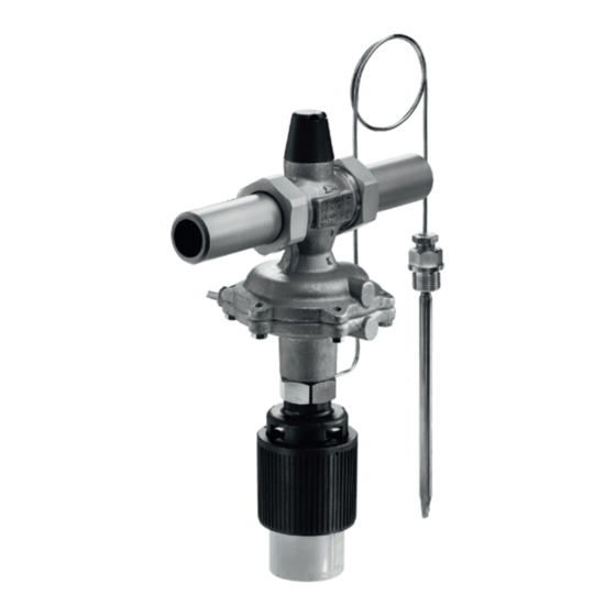
- Page 1 EB 3132-3 EN Translation of original instructions Type 2479/2430 Differential Pressure and Temperature Regulator with Flow Limitation Self-operated Regulators Edition June 2020...
- Page 2 Note on these mounting and operating instructions These mounting and operating instructions assist you in mounting and operating the device safely. The instructions are binding for handling SAMSON devices. The images shown in these instructions are for illustration purposes only. The actual product may vary.
-
Page 3: Table Of Contents
Notes on possible severe personal injury ............1-4 Notes on possible personal injury ..............1-5 Notes on possible property damage .............1-7 Markings on the device ................2-1 2.1 Nameplate of Type 2479 Valve ..............2-1 2.2 Nameplate of Type 2430 Control Thermostat ..........2-2 Location of the nameplate on valve and control thermostat ......2-3 2.4 Material identification number ..............2-4... - Page 4 Ordering spare parts and operating supplies ..........9-6 Decommissioning ..................10-1 Removal ....................11-1 11.1 Removing the control thermostat ..............11-1 11.2 Removing the regulator from the pipeline ............11-1 Repairs ....................12-1 12.1 Returning devices to SAMSON ..............12-1 Disposal ....................13-1 Certificates ....................14-1 Annex......................15-1 15.1 Tightening torques ..................15-1 15.2 Lubricant ....................15-1 15.3 Tools ......................15-1...
-
Page 5: Safety Instructions And Measures
In case operators intend to use the regulators in other applications or conditions than specified, contact SAMSON. SAMSON does not assume any liability for damage resulting from the failure to use the de- vice for its intended purpose or for damage caused by external forces or any other external factors. - Page 6 Hazards resulting from the special working conditions at the installation site of the regulator must be identified in a risk assessment and prevented through the corresponding safety in- structions drawn up by the operator. We also recommend checking the hazards posed by the process medium being used (e.g. u GESTIS (CLP) hazardous substances database). Î Observe safety measures for handling the device as well as fire prevention and explosion protection measures. Safety features The Type 2479/2430 Regulator does not have any special safety features. Revisions and other modifications Revisions, conversions or other modifications of the product are not authorized by SAMSON. They are performed at the user's own risk and may lead to safety hazards, for example. Fur- thermore, the product may no longer meet the requirements for its intended use. EB 3132-3 EN...
- Page 7 This also applies to the start-up and shutdown procedures. Start-up and shutdown procedures fall within the scope of the operator's duties and, as such, are not part of these mounting and operating instructions. SAMSON is unable to make any statements about these procedures since the operative details (e.g. differential pressures and temperatures) vary in each individual case and are only known to the operator.
-
Page 8: Notes On Possible Severe Personal Injury
Safety instructions and measures Referenced documentation The following documents apply in addition to these mounting and operating instructions: − Mounting and operating instructions for e.g. Type 1 N/NI Strainer u EB 1010 Type 2 N/NI Strainer e.g. u EB 1015 e.g. Type 2430 Control Thermostat u EB 2430 − Data sheets for e.g. Accessories for Series 43 Regulators u T 2176 − Mounting and operating instructions as well as data sheets for additional fittings... -
Page 9: Notes On Possible Personal Injury
Safety instructions and measures 1.2 Notes on possible personal injury WARNING Risk of personal injury through incorrect operation, use or installation as a result of information on the regulator being illegible. Over time, markings, labels and nameplates on the regulator may become covered with dirt or become illegible in some other way. As a result, hazards may go unno- ticed and the necessary instructions not followed. - Page 10 Safety instructions and measures WARNING Damage to health relating to the REACH regulation. If a SAMSON device contains a substance which is listed as being a substance of very high concern on the candidate list of the REACH regulation, this circumstance is indi- cated on the SAMSON delivery note. Î Information on safe use of the part affected u www.samsongroup.com/en/ about-samson/material-compliance/reach-regulation/ Risk of personal injury due to residual process medium in the regulator.
-
Page 11: Notes On Possible Property Damage
The lubricants to be used depend on the regulator material. Unsuitable lubricants may corrode and damage surfaces. Î Only use lubricants approved by SAMSON. When in doubt, consult SAMSON. Risk of leakage and regulator damage due to excessively high or low tightening torques. - Page 12 Î Do not dismantle the regulator. Î Only perform allowed activities on the regulator. Î Contact SAMSON's After-sales Service before replacing spare parts. Note SAMSON's After-sales Service can support you concerning lubricant, tightening torques and tools approved by SAMSON. EB 3132-3 EN...
-
Page 13: Markings On The Device
2 Type designation Model number and material number 4 Flow rate set point range in m³/h Differential pressure at the restriction in bar Max. perm. differential pressure Δp in bar 7 Flow coefficient K 8 Max. perm. temperature in °C 9 Pressure rating PN Valve size, pressure rating and the arrow indicating the direction of flow are cast into the body. Fig. 2-1: Nameplate for Type 2479 Valve EB 3132-3 EN... -
Page 14: Nameplate Of Type 2430 Control Thermostat
Markings on the device 2.2 Nameplate of Type 2430 Control Thermostat 1 Model number 2004 2 Type designation 0062 3 Material number 4 CE marking 5 Temperature range in °C and °F Register number (type test according to DIN EN 14597) Fig. 2-2: Nameplate of the Type 2430 Control Thermostat EB 3132-3 EN... -
Page 15: Location Of The Nameplate On Valve And Control Thermostat
Markings on the device 2.3 Location of the nameplate on valve and control thermostat Red brass body Spheroidal graphite iron body Location of the nameplate Location of the nameplate Top view Type 2430 Fig. 2-3: Locations of the nameplates on the body EB 3132-3 EN... -
Page 16: Material Identification Number
Markings on the device 2.4 Material identification number 2.4.1 Type 2479 Valve The material is indicated on the body. Speci- fying the material number, you can contact us to find out more details. This is specified on the nameplate (item 3). For more details on the nameplate, see sec- tion 2.1. -
Page 17: Design And Principle Of Operation
Î See Fig. 3-1 and Fig. 3-2 force of the set point spring (5). The regulator consists of the Type 2479 Valve with restriction, seat and plug and the The temperature of the medium creates a closing actuator with operating diaphragm pressure in the temperature sensor. - Page 18 Design and principle of operation Fig. 3-1: Functional diagram of regulator, DN 32 to 50 EB 3132-3 EN...
- Page 19 Design and principle of operation Fig. 3-2: Functional diagram of regulator, DN 15 to 25 Legend for Fig. 3-1 and Fig. 3-2 Valve body 6.2 Overload protection 21 Set point spring 1.1 Connection nut with seal and 6.3 Actuator cover Set point adjuster (tempera- welding end ture) Housing screws 1.2 Restriction 23 Operating bellows Pin of operating element...
-
Page 20: Additional Fittings
· The minimum required plant differential pressure Δp = Δp ∆p across the valve is calculated as follows: restriction ∆p Minimum differential pressure across the valve in bar ∆p Differential pressure created at the restriction for measuring the flow rate in the regulator restriction · Adjusted flow rate in m³/h Valve flow coefficient in m³/h Fig. 3-3: Type 2479/2430 (installation example) EB 3132-3 EN... -
Page 21: Technical Data
− Suitable for gases and liquids − Max. temperature 150 °C Note − Temperature set points from 0 to 150 °C The Type 2479/2430 Regulator is not a safety valve. If necessary, a suitable over- − Limit signals up to 120 °C pressure protection must be installed on site − Valve size DN 15 to 50... - Page 22 150 °C (see Fig. 3-1). The minimum tem- perature is limited by the accessories used and the actuator's diaphragm material (u T 3132). Noise emissions SAMSON is unable to make general state- ments about noise emissions. The noise emis- sions depend on the regulator version, plant facilities, process medium and operating conditions. Dimensions and weights Table 3-5 provides a summary of the dimen- sions and weights.
- Page 23 Design and principle of operation Table 3-1: Technical data · Valve · All pressures in bar (gauge) Valve size 1) 1) 1) Body with 12.5 16.0 20.0 2) 2) 2) screwed ends coefficient Flanged body – 12.5 20.0 25.0 Body with 0.55 0.45 screwed ends value...
- Page 24 20 K above the adjusted set point Max. permissible pressure at sensor with 40 bar thermowell Capillary tube length 5 m 2 m 2) At temperatures below freezing: ice formation may damage the plant and especially the valve. Special version: Type 2430 with 5 m and 10 m capillary tube · Type 2439 with 5 m capillary tube Table 3-4: Materials · Material number according to DIN EN Type 2479 Valve Red brass CC499K (Rg 5) · Spheroidal graphite iron EN-GJS-400- Body 18-LT 1) Seat Stainless steel 1.4305 Plug Brass (resistant to dezincification) with EPDM soft seal Valve spring Stainless steel 1.4310...
- Page 25 Design and principle of operation Table 3-5: Dimensions in mm · Weights in kg Type 2479 Valve Valve size Length L Pipe Ød 21.3 26.9 33.7 42.4 48.3 60.3 Connection R G ¾ G 1 G 1¼ G 1¾ G 2 G 2½ Width across flats SW Height H 1) Height H1 1)
- Page 26 Design and principle of operation Dimensional drawings Valve with male thread and control thermostat DN 15 to 25 with welding ends DN 32 to 50 with welding ends ØD Ød Ød Ød Ød Thermowell Packing Thermowell Packing Valve with threaded ends Valve with screwed-on flanges Valve with flanged body Fig. 3-4: Dimensions 3-10 EB 3132-3 EN...
-
Page 27: Shipment And On-Site Transport
Report any damage to regulator (e.g. to install it into the pipeline). SAMSON and the forwarding agent (re- Î Leave the regulator in its transport con- fer to delivery note). -
Page 28: Storing The Regulator
Î Observe the storage instructions. Î Store elastomers away from lubricants, Î Avoid long storage times. chemicals, solutions and fuels. Î Contact SAMSON in case of different Î We recommend a storage temperature of storage conditions or longer storage 15 °C for elastomers. -
Page 29: Installation
Î Make sure the direction of flow matches Pipeline routing the direction indicated by the arrow on The inlet and outlet lengths vary depending the body. on several variables and process conditions Î Contact SAMSON if the mounting posi- and are intended as recommendations. Con- tion is not as specified above. tact SAMSON if the lengths are significantly shorter than the recommended lengths. DN 32 to 50 To ensure that the regulator functions proper- Î... - Page 30 All versions. Note If the sensor is to be used with a thermowell, Alternative mounting position, only use original SAMSON thermowells. control thermostat on top All versions, DN 15 to 25. Maximum medium temperature Weld a welding socket with G ½ or G ¾ fe- 110 °C male thread (to match the screw gland) at the place of installation.
- Page 31 Table 5-1 a 6x1 mm (stainless) steel pipe. shows the dynamic behavior of the Type 2430 Control Thermostat measured in The control line for tapping pressure from the water. pipeline (for Type 2479/2430) must be in- stalled upstream of the consumer. The pres- Capillary tube sure tapping point must at least three times Carefully run the capillary tube without the nominal size (DN) away from any pipe bending or twisting it.
-
Page 32: Preparation For Installation
Installation 5.2 Preparation for installation Proceed as follows: Î Lay out the necessary material and tools The valve and control thermostat of regula- to have them ready during installation tors that have not yet been assembled can work. be assembled before or after the valve has Î... - Page 33 Installation Table 5-1: Dynamic behavior of Type 2430 Control Thermostat (adsorption principle) Type 2430 Sensor Ø Time constant [s] Without thermowell With thermowell 9.5 mm Adsorption principle 16 mm Air sensor – 1) Thermowell not possible Table 5-2: Inlet and outlet lengths min. min. b x DN a x DN Inlet length...
- Page 34 2 Strainer 3 Type 2479/2430 4 Thermometer 5 Pressure gauge – 6 Temperature sensor 7 Control line 8 Shut-off valve Fig. 5-2: Type 2479/2430 (installation example) Correct min. min. 3 x DN 3 x DN Connection at the side – optimal min. 3 x DN Connection at the top –...
-
Page 35: Installation
(10). Ob- Risk of regulator damage due to the use of serve the specified tightening torques unsuitable tools. (see 'Tightening torques' in Annex). Î Only use tools approved by SAMSON 7. Mount the control line. Observe the spec- (see 'Tools' in Annex). ified tightening torques (see 'Tightening torques' in Annex). -
Page 36: Cleaning The Pipeline
Installation 5.3.2 Cleaning the pipeline 5.4 Testing the regulator We recommend additionally flushing the DANGER pipeline without the installed regulator be- fore start-up. In this case, install a suitable Risk of bursting due to incorrect opening of length of pipe into the pipeline in place of pressurized equipment or components. -
Page 37: Leak Test
Î Wear protective clothing and safety gloves. Note The plant operator is responsible for per- SAMSON regulators are delivered ready for forming the pressure test. SAMSON's Af- use. To test the regulator functioning before ter-sales Service can support you to plan start-up or putting back the regulator into and perform a pressure test for your plant. -
Page 38: Insulation
Installation 5.5 Insulation To insulate cold systems, we recommend first filling the plant and carefully rinsing it. The regulator must not yet be insulated at this stage. 1. Start up the plant and adjust the set point (see the 'Start-up' section). 2. Shut down the plant again and let it heat up until the condensation water has dried off. -
Page 39: Start-Up
Start-up 6 Start-up WARNING The work described in this section is only to Risk of personal injury due to pressurized be performed by personnel appropriately components and process medium being dis- qualified to carry out such tasks. charged. Î Do not loosen the control line while the valve is pressurized. -
Page 40: Start-Up And Putting The Device Back Into Operation
Start-up 6.1 Start-up and putting the 6.2 Starting up the plant device back into operation 1. Open the shut-off valves slowly prefera- bly starting from the upstream pressure 1. Depending on the field of application, side. Afterwards, open all the valves on allow the regulator to cool down or the consumer side (downstream of the warm up to reach ambient temperature regulator). -
Page 41: Operation
Operation 7 Operation 7.1 Adjusting the set points Immediately after completing start-up or The flow rate and temperature can be adjust- placing the regulator back into service (see ed separately from each other. the 'Start-up' section), the regulator is ready 7.2 Adjustment of the flow rate for use. Î The control and shut-off valves as well as WARNING all consumers or a bypass valve (if in- Risk of burn injuries due to hot or cold com-... - Page 42 Operation Adjustment NOTICE For valve sizes DN 15 to 25, adjust the flow Risk of damage to the restriction stem rate at the side adjustment screw (12) through one-side loading (DN 15 to 25) For valve sizes DN 32 to 50, adjust the flow while turning the adjustment screw clock- rate at the adjustment screw (12) underneath wise. the cap using a 4 mm hex wrench. Proceed Completely close the restriction only by turn- as follows: ing the set point adjuster (22) at the control...
-
Page 43: Adjusting The Temperature
Note For special versions with a scaled cap, the Example: flow rate adjustment limit can be adjusted directly using the The Type 2479/2430 Regulator, DN 15, scaled cap (one marked scale division corre- flow rate range K = 0.25 to 0.64 m³/h is sponds to one turn of the set point screw). - Page 44 Operation Solution: Include the differential pressure across the restriction assumed to be 0.2 bar. A line Î Sequence: points A to E in diagram representing this value is drawn from point A (Fig. 7-1). across to the right and results in point B. The calculation is based on the pressure Point B is situated on the same straight line drop Δp across the plant, therefore, this val- for the differential pressure of 0.6 bar to be...
- Page 45 Operation Pressure loss Fixed across the plant differential Δp in bar pressure set point Limitation Turns of the set point adjuster (scale divisions) [m³/h] 0.06 0.18 DN 15 0.30 K vs 0.4 0.42 0.54 0.66 0.78 0.90 1.02 1.14 DN 15 K vs 1 Flow range Differential pressure at...
- Page 46 Operation Pressure loss across the plant Δp in bar Turns of the set point adjuster (scale divisions) [m³/h] 0.06 0.18 DN 15 0.30 K vs 0.4 0.42 0.54 0.66 0.78 0.90 1.02 1.14 DN 15 K vs 1 Flow range Differential pressure at restriction Δp in bar Fig. 7-2: Adjustment diagram DN 15 (20, 25) with K...
- Page 47 Operation Pressure loss across the plant Δp in bar Turns of the set point adjuster (scale divisions) [m³/h] DN 15 K vs 2.5 DN 15 K vs 4 DN 20 K vs 6.3 DN 25 K vs 8 Flow range Differential pressure at restriction Δp in bar Fig. 7-3: Adjustment diagram DN 15 to 25 with K...
- Page 48 Operation Pressure loss across the plant Δp in bar Turns of the set point adjuster (scale divisions) [m³/h] DN 32 K vs 12.5 DN 40 K vs 16/20 DN 50 K vs 20/25 Flow range Differential pressure at restriction Δp in bar Fig. 7-4: Adjustment diagram DN 32 to 50 with K = 12.5 to 25 EB 3132-3 EN...
-
Page 49: Malfunctions
Insufficient pressure pulses on the oper- Î Clean the control line and screw fittings. ating diaphragm Î Remove foreign particles. Foreign particles blocking the plug Î Replace damaged parts. Î Contact SAMSON's After-sales Service. Î Replace the damaged seat and plug. Seat and plug are worn or leak. Î Contact SAMSON's After-sales Service. Î Check the sizing. Valve too large for control task (flow Î Change K... - Page 50 Î Check the sizing. Regulator or K coefficient too Î Change K coefficient, if necessary or in- small stall a different sized regulator. Î Contact SAMSON's After-sales Service. Î Check set point range. Incorrect set point range selected Î Contact SAMSON's After-sales Service. Safety device, e.g. pressure limiter, has Î Check plant. If necessary, unlock safety device. been triggered Î Compare differential pressure in the plant with Temperature at the the plant’s drag.
- Page 51 Î Check the sizing. Loud noises High flow velocity, cavitation Î Install larger regulator, if necessary. Note Contact SAMSON's After-sales Service for malfunctions not listed in the table. The malfunctions listed in section 8.1 are caused by mechanical faults and incorrect SAMSON's After-sales Service can support regulator sizing. In the simplest case, the you in drawing up an inspection and test functioning can be restored following the plan for your plant.
-
Page 52: Emergency Action
2. Perform troubleshooting (see sec- tion 8.1). 3. Rectify those malfunctions that can be remedied based on the instructions pro- vided here. Contact SAMSON's Af- ter-sales Service in all other cases. Putting the regulator back into operation after a malfunction See the 'Start-up' section. EB 3132-3 EN... -
Page 53: Servicing
Risk of regulator damage due to the use of become very hot or cold. Risk of burn inju- unsuitable tools. ries. Î Only use tools approved by SAMSON Î Allow components and pipelines to cool (see 'Tools' in Annex). down or warm up to the ambient tem- perature. -
Page 54: Preparing The Valve For Service Work
The regulator was checked by SAMSON before it left the factory. 1. Lay out the necessary material and tools − Certain test results certified by SAMSON to have them ready for the service work. lose their validity when the regulator is 2. - Page 55 Servicing Fig. 9-1: Functional diagram of regulator, DN 32 to 50 EB 3132-3 EN...
- Page 56 Servicing Fig. 9-2: Functional diagram of regulator, DN 15 to 25 Legend for Fig. 9-1 and Fig. 9-2 1 Valve body 6.1 Operating diaphragm unit 14 Cap 1.1 Connection nut with seal and 6.2 Overload protection 20 Control thermostat welding end 6.3 Actuator cover 21 Set point spring 1.2 Restriction 7 Housing screws 22 Set point adjuster (temperature) 2 Seat...
-
Page 57: Service Work
Servicing 9.3 Service work 5. Clamp the valve into a suitable fixture. 6. Unscrew nuts and bolts (7) from the actu- Î Before performing any service work, ator (6). Remove the actuator case (6.3). preparations must be made to the regu- 7. Lift the operating diaphragm unit (6.1) lator (see section 9.1). together with the diaphragm off the Î... -
Page 58: Replacing The Control Thermostat
Servicing 9.3.3 Replacing the control 9.4 Ordering spare parts and thermostat operating supplies Contact your nearest SAMSON subsidiary Removing the control thermostat or SAMSON's After-sales Service for infor- 1. Put the regulator out of operation (see mation on spare parts, lubricants and tools. the 'Decommissioning' section). 2. Unscrew the coupling nut (10) from the... -
Page 59: Decommissioning
Decommissioning 10 Decommissioning WARNING The work described in this section is only to Risk of personal injury due to pressurized be performed by personnel appropriately components and process medium being dis- qualified to carry out such tasks. charged. Î Do not loosen the control line while the valve is pressurized. - Page 60 Decommissioning To decommission the regulator for service work or disassembly, proceed as follows: 1. Close the shut-off valve (1) on the up- stream side of the regulator. 2. Close the shut-off valve (6) on the down- stream side of the regulator. 3. Completely drain the pipelines and valve. 4. Depressurize the plant. 5. If necessary, allow the pipeline and reg- ulator components to cool down or warm up to the ambient temperature.
-
Page 61: Removal
Removal 11 Removal 11.1 Removing the control thermostat The work described in this section is only to be performed by personnel appropriately 1. Pull the sensor out of the thermowell. In qualified to carry out such tasks. cases where a thermowell is not used, unscrew the screw gland and pull out the WARNING sensor. - Page 62 11-2 EB 3132-3 EN...
-
Page 63: Repairs
& Support > After-sales Service. Î Do not perform any repair work on your After checking your registration, we will own. send you a return merchandise authori- Î Contact SAMSON's After-sales Service zation (RMA). for repair work. 6. Attach the RMA (together with the Decla- ration on Decontamination) to the out- 12.1 Returning devices to... - Page 64 12-2 EB 3132-3 EN...
-
Page 65: Disposal
Disposal 13 Disposal Î Observe local, national and internation- al refuse regulations. Î Do not dispose of components, lubricants and hazardous substances together with your household waste. EB 3132-3 EN 13-1... - Page 66 13-2 EB 3132-3 EN...
-
Page 67: Certificates
Certificates 14 Certificates The EU declarations of conformity are inclu- ded on the next pages: − EU declaration of conformity in compli- ance with Pressure Equipment Directive 2014/68/EU on page 14-2. EB 3132-3 EN 14-1... - Page 68 Certificates Modul H/Module H, Nr./No. / N° CE-0062-PED-H-SAM 001-16-DEU-rev-A SAMSON erklärt in alleiniger Verantwortung für folgende Produkte:/For the following products, SAMSON hereby declares under its sole responsibility: Ventile für Druck-, Differenzdruck-, Temperatur- und Volumenstromregler/Valves for pressure, temperature, flowregulators and differential pressure regulators Typ 2336, 2373, 2375, 44-1B, 44-2, 44-3, 44-4, 44-6B, 44-9, 45-1, 45-2, 45-3, 45-4, 45-6, (Erz.-Nr.
- Page 69 Certificates EB 3132-3 EN 14-3...
- Page 70 14-4 EB 3132-3 EN...
-
Page 71: Annex
DN 15 to 25 SW 10 Body screws (7) DN 32 SW 13 DN 40 and 50 Coupling nut (10) SW 36 DN 15 to 50 Control line connection (11) – DN 15 to 50 15.2 Lubricant SAMSON's After-sales Service can support you concerning lubricants and sealants ap- proved by SAMSON. 15.3 Tools SAMSON's After-sales Service can support you concerning tools approved by SAMSON. EB 3132-3 EN 15-1... -
Page 72: Spare Parts
Plug 129 Screws Lock nut 134 Seal Restriction 182 Restriction 27 Stopper 185 Cap 30 Body 186 Seal 34 Seat 211 Nipple 54 Guide bushing 212 Seal 110 Diaphragm case 220 Diaphragm Fig. 15-1: Type 2479 Valve, DN 15 to 25 15-2 EB 3132-3 EN... - Page 73 Annex Fig. 15-2: Type 2479 Valve, DN 32 to 50 EB 3132-3 EN 15-3...
-
Page 74: After-Sales Service
E-mail address You can reach our after-sales service at aftersalesservice@samsongroup.com. Addresses of SAMSON AG and its subsid- iaries The addresses of SAMSON, its subsidiaries, representatives and service facilities world- wide can be found on our website (u www.samsongroup.com) or in all... - Page 75 EB 3132-3 EN...
- Page 76 EB 3132-3 EN...
- Page 77 EB 3132-3 EN...
- Page 78 EB 3132-3 EN EB 3132-3 EN SAMSON AKTIENGESELLSCHAFT Weismüllerstraße 3 · 60314 Frankfurt am Main, Germany Phone: +49 69 4009-0 · Fax: +49 69 4009-1507 samson@samsongroup.com · www.samsongroup.com...
Need help?
Do you have a question about the 2479 and is the answer not in the manual?
Questions and answers