Sign In
Upload
Download
Table of Contents
Contents
Add to my manuals
Delete from my manuals
Share
URL of this page:
HTML Link:
Bookmark this page
Add
Manual will be automatically added to "My Manuals"
Print this page
×
Bookmark added
×
Added to my manuals
Manuals
Brands
Samson Manuals
Controller
2469
Mounting and operating instructions
Samson 2469 Mounting And Operating Instructions
Flow and temperature regulator
Hide thumbs
1
Table Of Contents
2
3
4
5
6
7
8
9
10
11
12
13
14
15
16
page
of
16
Go
/
16
Contents
Table of Contents
Troubleshooting
Bookmarks
Table of Contents
Table of Contents
1 Design and Principle of Operation
2 Installation
Mounting Position
Strainer
Additional Installation Instructions
Installing the Temperature Sensor
Capillary Tube
Mounting the Thermostat
3 Operation
Start-Up
Set Point Adjustment
Flow Rate
Temperature
4 Maintenance - Replacing Parts
Cleaning or Replacing the Plug
Replacing the Diaphragm
5 Troubleshooting
6 Description of the Nameplate
7 Customer Inquiries
8 Dimensions in MM and Weights
Advertisement
Quick Links
1
Mounting Position
2
Design and Principle of Operation
3
Operation
4
Set Point Adjustment
5
Description of the Nameplate
Download this manual
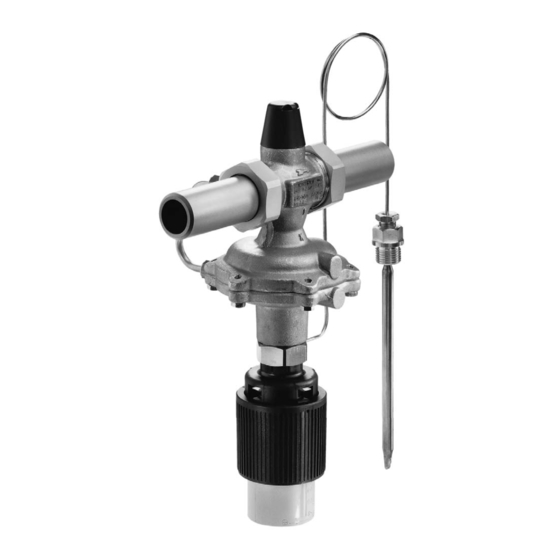
Flow and Temperature Regulator
Type 2469/2430 K
Fig. 1 · Type 2469/2430 K
Mounting and
Operating Instructions
EB 3132-2 EN
Edition November 2011
Table of
Contents
Previous
Page
Next
Page
1
2
3
4
5
Advertisement
Table of Contents
Need help?
Do you have a question about the 2469 and is the answer not in the manual?
Ask a question
Questions and answers
Related Manuals for Samson 2469
Controller Samson 2488 N Mounting And Operating Instructions
Flow regulator with electric actuator (12 pages)
Controller Samson 2422 Mounting And Operating Instructions
Self-operated pressure regulators (21 pages)
Controller Samson 2403 Mounting And Operating Instructions
Safety temperature monitor self-operated temperature regulators (32 pages)
Controller Samson 2479 Mounting And Operating Instructions
Differential pressure and temperature regulator with flow limitation (78 pages)
Controller Samson 2213 Mounting And Operating Instructions
Safety temperature monitor, self-operated regulators (40 pages)
Controller Samson 2430 K Mounting And Operating Instructions
Flow and temperature regulator (16 pages)
Controller Samson 2357-11 Mounting And Operating Instructions
Self-operated pressure regulators, pressure build-up regulator, excess pressure valve (16 pages)
Controller Samson 2371-10 Mounting And Operating Instructions
Pressure regulators; pressure reducing valves for the food and pharmaceutical industries (36 pages)
Controller Samson 2357-3 Mounting And Operating Instructions
Self-operated pressure regulators, pressure build-up regulator (12 pages)
Controller Samson 2357-3 Mounting And Operating Instructions
Pressure build-up regulator with non-return unit at port c ports a and b with soldering nipple with ball-type bushing (40 pages)
Controller Samson 2357-3 Mounting And Operating Instructions
Pressure build-up regulator (60 pages)
Controller Samson 2357-1 Mounting And Operating Instructions
Pressure regulator/excess pressure valve (60 pages)
Controller Samson 2780-1 Mounting And Operating Instructions
Pneumatic actuators (52 pages)
Controller Samson 2780-2 Mounting And Operating Instructions
Pneumatic actuators (52 pages)
Controller Samson 2357-31 Mounting And Operating Instructions
Pressure build-up regulator (12 pages)
Controller Samson 5827 Mounting And Operating Instructions
(92 pages)
This manual is also suitable for:
2430 k
Table of Contents
Print
Rename the bookmark
Delete bookmark?
Delete from my manuals?
Login
Sign In
OR
Sign in with Facebook
Sign in with Google
Upload manual
Upload from disk
Upload from URL


Need help?
Do you have a question about the 2469 and is the answer not in the manual?
Questions and answers