Samson 2357-3 Mounting And Operating Instructions
Self-operated pressure regulators, pressure build-up regulator
Hide thumbs
Also See for 2357-3:
- Mounting and operating instructions (40 pages) ,
- Mounting and operating instructions (60 pages)

Related Manuals for Samson 2357-3


Summary of Contents for Samson 2357-3
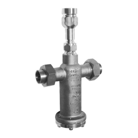
- Page 1 Self-operated Pressure Regulators Pressure Build-up Regulator Type 2357-3 Fig. 1 · Type 2357-3 with non-return unit at port C Mounting and Operating Instructions EB 2559 EN Edition February 2008...
-
Page 2: Table Of Contents
Contents Contents Page Design and principle of operation ..... . 4 Installation ....... . . 6 Mounting position . - Page 3 Safety instructions General safety instructions The regulators must be installed, started up and serviced by fully trained and qualified personnel only, observing the accepted industry codes and practices. Make sure employees or third persons are not exposed to any danger. All safety instructions and warnings in these instructions, particularly those concerning installation, start-up, and maintenance, must be observed.
-
Page 4: Design And Principle Of Operation
Design and principle of operation Design principle spring force of the set point spring (5) and operation opens the tubular plug (2) when the pressure rises above the set point by approx. 0.5 bar. The pressure regulator is especially designed The pressures are equalized and the medium for the use in cryogenic service to keep the escapes through the inside of the tubular plug... - Page 5 Design and principle of operation Pressure build-up plug Tubular plug Soldering nipple with ball-type bushing (accessories) Operating bellows Set point spring Set point adjuster with lock nut Body Closing spring Strainer optionally in A or B (accessories) Non-return unit (accessories) Fig.
-
Page 6: Installation
Installation Installation Shut-off valve We recommend installing a hand-operated Mounting position shut-off valve both upstream of the strainer The pressure regulator must be in- and downstream of the regulator to be able to stalled with the actuator housing shut down the plant for cleaning. pointing downward (port C facing Install a pressure gauge both upstream and upward). -
Page 7: Operation
Operation Operation Set point adjustment Set point in bar The pressure regulator is adjusted at the factory to the set points listed in the table. However, you can change them by turning the set point adjuster (6). When pressure gauges are installed in the connected pipelines, you can adjust the de- sired set point directly while monitoring the 25 to 40 bar... -
Page 8: Dimensions In Mm (Accessories)
Dimensions in mm Dimensions in mm M40 x 1.5 Ø 80 Type 2357-3 · Standard version M26 x 1.5 Welded on site M40 x 2 Ø28 Ø80 Type 2357-3 · Special version (stainless steel) Fig. 4 · Dimensions EB 2559 EN... - Page 9 Accessories · Dimensions in mm Accessories Table 2 · Accessories Accessories Order number Non-return unit for port C, connection for ball-type bushing M40x2 1400-7092 2 soldering nipples for 28 mm pipe, PN 40 For port A and B 1400-7090 1 soldering nipple for 28 mm pipe, PN 40 For port C with non-return unit 1400-7300 1 soldering nipple for 18 mm pipe, PN 40...
- Page 10 EB 2559 EN...
- Page 11 EB 2559 EN...
- Page 12 SAMSON AG · MESS- UND REGELTECHNIK Weismüllerstraße 3 · 60314 Frankfurt · Germany Phone: +49 69 4009-0 · Fax: +49 69 4009-1507 EB 2559 EN Internet: http://www.samson.de...
Need help?
Do you have a question about the 2357-3 and is the answer not in the manual?
Questions and answers