Table of Contents
Advertisement
Quick Links
EB 2557 EN
Translation of original instructions
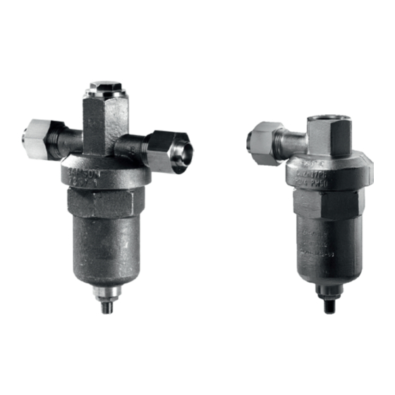
Type 2357-1 Pressure Regulator (pressure
Type 2357-2 Pressure Regulator
build-up regulator or pressure reducing valve)
(excess pressure valve)
Type 2357-1 Pressure Regulator · Type 2357-2 Excess Pressure
Valve
Self-operated Pressure Regulators for special applications
Edition March 2021
Advertisement
Table of Contents

Related Manuals for Samson 2357-1


Summary of Contents for Samson 2357-1
- Page 1 EB 2557 EN Translation of original instructions Type 2357-1 Pressure Regulator (pressure Type 2357-2 Pressure Regulator build-up regulator or pressure reducing valve) (excess pressure valve) Type 2357-1 Pressure Regulator · Type 2357-2 Excess Pressure Valve Self-operated Pressure Regulators for special applications Edition March 2021...
- Page 2 Note on these mounting and operating instructions These mounting and operating instructions assist you in mounting and operating the device safely. The instructions are binding for handling SAMSON devices. The images shown in these instructions are for illustration purposes only. The actual product may vary.
-
Page 3: Table Of Contents
Start-up and putting the device back into operation ........6-2 Starting up the plant when vapors and liquids are controlled ......6-2 Operation ....................7-1 Adjusting the set point .................7-1 Malfunctions ....................8-1 Troubleshooting ..................8-1 8.1.1 Type 2357-1 as pressure reducing valve ............8-1 8.1.2 Type 2357-1 as pressure build-up regulator ..........8-2 8.1.3 Type 2357-2 as excess pressure valve............8-3 Emergency action ..................8-4 EB 2557 EN... - Page 4 Cleaning and exchanging the seat and plug ..........9-5 Ordering spare parts and operating supplies ..........9-6 Decommissioning ..................10-1 Removal ....................11-1 11.1 Removing the regulator from the pipeline ............11-1 Repairs ....................12-1 12.1 Returning devices to SAMSON ..............12-1 Disposal ....................13-1 Certificates ....................14-1 Annex......................15-1 15.1 Tightening torques ..................15-1 15.2 Tools ......................15-1 15.3...
-
Page 5: Safety Instructions And Measures
Therefore, operators must ensure that the regulators are only used in operating conditions that meet the specifications used for sizing the devices at the ordering stage. In case operators intend to use the regulator in other applications or con- ditions than specified, contact SAMSON. SAMSON does not assume any liability for damage resulting from the failure to use the de- vice for its intended purpose or for damage caused by external forces or any other external factors. Î Refer to the technical data and nameplate for limits and fields of application as well as possible uses. - Page 6 Revisions and other modifications Revisions, conversions or other modifications of the product are not authorized by SAMSON. They are performed at the user's own risk and may lead to safety hazards, for example. Fur- thermore, the product may no longer meet the requirements for its intended use. Warning against residual hazards To avoid personal injury or property damage, plant operators and operating personnel must prevent hazards that could be caused in the regulators by the process medium, the operating pressure or by moving parts by taking appropriate precautions.
- Page 7 Start-up and shutdown procedures fall within the scope of the operator's duties and, as such, are not part of these mounting and operating instructions. SAMSON is unable to make any statements about these procedures since the operative details (e.g. differential pressures and temperatures) vary in each individual case and are only known to the operator.
-
Page 8: Notes On Possible Severe Personal Injury
Safety instructions and measures − Mounting and operating instructions as well as data sheets for additional fittings (e.g. shut-off valves, pressure gauges etc.). 1.1 Notes on possible severe personal injury DANGER Risk of bursting in the regulator. Regulators and pipelines are pressure equipment. Impermissible pressure or improper opening of the regulator can lead to regulator components bursting. Î... -
Page 9: Notes On Possible Personal Injury
Î Wear protective clothing and safety gloves. Damage to health relating to the REACH regulation. If a SAMSON device contains a substance which is listed as being a substance of very high concern on the candidate list of the REACH regulation, this circumstance is indi- cated on the SAMSON delivery note. -
Page 10: Notes On Possible Property Damage
Risk of regulator damage due to the use of unsuitable tools. Certain tools are required to work on the regulator. Î Only use tools approved by SAMSON. When in doubt, consult SAMSON. Risk of the process medium being contaminated through the use of unsuitable lubri- cants and/or contaminated tools and components. - Page 11 Î In the event that the formation of ice restricts the movement of the springs, we rec- ommend using a heat gun to melt the ice. Note SAMSON's After-sales Service can support you concerning lubricant, tightening torques and tools approved by SAMSON. EB 2557 EN...
- Page 12 Safety instructions and measures EB 2557 EN...
-
Page 13: Markings On The Device
Markings on the device 2 Markings on the device 2.1 Nameplate inscriptions Nameplate on the front of the body Back of the body 1 Type designation and year of manufacture 2 Set point range/default set point setting 3 Material number and device index 4 Serial number 5 Customer-specific details Fig. 2-1: Valve nameplate EB 2557 EN... -
Page 14: Material Identification Number
Markings on the device 2.2 Material identification number Specifying the material number, you can contact us to find out which material is used. The material number is specified on the nameplate (3). For more details on the nameplate, see sec- tion 2.1. EB 2557 EN... -
Page 15: Design And Principle Of Operation
Î Excess pressure valve Direction of flow always from port A to port Î See Fig. 3-1 B. The valve is closed when no pressure is Type 2357-1 applied. The pressure at port A is transmitted internally to the operating diaphragm (3). Î Pressure build-up regulator The positioning force produced opposes the Direction of flow from port B to port A. The... - Page 16 Design and principle of operation Type 2357-2 Type 2357-1 Top section of the body Bottom section of the 2.1 Plug body Operating diaphragm 10 Set point adjuster 11 Lock nut Gasket (bottom section of the body) Non-return unit Gasket (top section of (optional) the body) 13 Filter...
-
Page 17: Additional Fittings
Regulators can be insulated to reduce heat when the plant is not operated for extended energy transfer. periods. Refer to the instructions in the 'Installation' section. Cryogenic tank Type 2357-1 Pressure Build-up Regulator Type 2357-2 Excess Pressure Valve (economizer) Type 2357-1 Pressure Reducing Valve Type 2040 Temperature Monitor 6.1 Shut-off valve... -
Page 18: Technical Data
Noise emissions gases and vapors − Temperature range from –196 to SAMSON is unable to make general state- +200 °C ments about noise emissions. The noise emis- − Set points from 0.2 to 40 bar sions depend on the regulator version, plant −... - Page 19 Max. permissible Type 2357-1 Gases: 30 bar · Liquids: 6 bar differential pressure Type 2357-2 3 bar (> 3 bar only with special accessories; K coefficient reduced to 0.02) ∆p Safety function for Type 2357-1 5 bar above the set point Temperature range –196 to +200 °C Conformity Further set point ranges on request For oxygen p = 40 bar Table 3-2: Materials · Material numbers according to DIN EN Type ...
- Page 20 Design and principle of operation Table 3-4: Dimensions in mm and weights in kg Type ... Regulator 2357-1 2357-2 PN 40 PN 50 PN 40 PN 50 Length L 110 mm 55 mm Length L1 150 mm 75 mm Height H 95 mm 140 mm 95 mm 140 mm Height H2 35 mm...
-
Page 21: Shipment And On-Site Transport
Î Observe the transport instructions. 2. Check the shipment for transportation damage. Report any damage to Transport instructions SAMSON and the forwarding agent Î Protect the regulator against external in- (refer to delivery note). fluences (e.g. impact). 3. Determine the weight and dimensions of Î Do not damage the corrosion protection the units to be lifted and transported in (paint, surface coatings). -
Page 22: Storing The Regulator
Î Observe the storage instructions. Special storage instructions for elastomers Î Avoid long storage times. Elastomer, e.g. O-rings Î Contact SAMSON in case of different Î We recommend a storage temperature of storage conditions or longer storage 15 °C/60 °F for elastomers. times. -
Page 23: Installation
The work described in this section is only to Î Observe the inlet and outlet lengths (see be performed by personnel appropriately Table 5-1). Contact SAMSON if the reg- qualified to carry out such tasks. ulator conditions or state of the medium process deviate. -
Page 24: Preparation For Installation
Installation 5.2 Preparation for installation Before installation, make sure the following Mounting orientation conditions are met: For gases and liquids above 80 °C/175 °F and steam − The regulator is clean and not damaged. − The regulator data on the nameplate (type designation, valve size, material, pressure rating etc.) match the plant con- ditions (size and pressure rating of the pipeline, medium temperature etc.). - Page 25 State of process Valve conditions Inlet length a Outlet length b medium Ma ≤ 0.3 Vapor Ma ≤ 0.3 Free of cavitation/w < 3 Liquid Cavitation producing noise/w ≤ 3 Cryogenic tank Type 2357-1 Pressure Build-up Regulator Type 2357-2 Excess Pressure Valve (economizer) Type 2357-1 Pressure Reducing Valve Type 2040 Temperature Monitor 6.1 Shut-off valve 6.2 Shut-off valve Pressure build-up vaporizer Final vaporizer Media 7/Media 5 Level Meter 10 Safety valve...
-
Page 26: Installation Activities
Risk of regulator damage due to the use of packed to be free of oil and grease for oxy- unsuitable tools. gen service as ready-to-install assemblies. Î Only use tools approved by SAMSON The activities listed below are necessary for (see 'Tools' in Annex). installation and before start-up of the regula- tors. -
Page 27: Installing The Regulator
Installation 5.3.1 Installing the regulator 5.4 Testing the regulator 1. Close the shut-off valves upstream and DANGER downstream of the regulator while the regulator is being installed. Risk of bursting due to incorrect opening of pressurized equipment or components. 2. Allow pipelines to reach ambient tem- Regulators and pipelines are pressure perature. -
Page 28: Leak Test
SAMSON's After-sales Service can support you to plan SAMSON regulators are delivered ready for and perform a pressure test for your plant. use. To test the regulator functioning before start-up or putting back the regulator into... -
Page 29: Start-Up
Start-up 6 Start-up NOTICE The work described in this section is only to Risk of impaired functioning of the be performed by personnel appropriately regulator and leakage at the joint due to qualified to carry out such tasks. installation under tension. − Bolt the regulator to the pipeline free of stress. -
Page 30: Start-Up And Putting The Device Back Into Operation
Start-up 6.1 Start-up and putting the device back into operation 1. Depending on the field of application, allow the regulator to cool down or warm up to reach ambient temperature before start up. 2. Slowly open the shut-off valves in the pipeline. Slowly opening these valves prevents a sudden surge in pressure and high flow velocities which can damage the valve. -
Page 31: Operation
Operation 7 Operation Set point adjuster Î Turn the set point adjuster clockwise () Immediately after completing start-up or to increase the pressure set point. placing the regulator back into service (see Î Turn the set point adjuster counterclock- the 'Start-up' section), the regulator is ready wise () to reduce the pressure set point. - Page 32 1 to 10 to 0.2 to 1 to 5 to 8 to Set point range 3 bar 25 bar 36 bar 2.5 bar 8 bar 25 bar 40 bar 2357-1 1 bar 12 bar 20 bar 1 bar 3 bar 12 bar 25 bar Set point adjusted at the factory (approx.) 2357-2 1 bar 13 bar 21 bar 1 bar 4 bar...
-
Page 33: Malfunctions
Malfunctions 8 Malfunctions 8.1 Troubleshooting 8.1.1 Type 2357-1 as pressure reducing valve Malfunction Possible reasons Recommended action Î Clean the seat and plug. Seat and plug are worn or Î Replace the damaged plug. leak. Î Contact SAMSON's After-sales Service. Î Remove foreign particles. -
Page 34: Type 2357-1 As Pressure Build-Up Regulator
Î Check the sizing. Loud flow- High flow velocity, cavitation. induced noise Î Install larger regulator, if necessary. 8.1.2 Type 2357-1 as pressure build-up regulator Malfunction Possible reasons Recommended action Î Clean the seat and plug. Seat and plug are worn or Î Replace the damaged plug. -
Page 35: Type 2357-2 As Excess Pressure Valve
Malfunction Possible reasons Recommended action Î Clean the seat and ball. Seat and ball are worn or leak. Î Contact SAMSON's After-sales Service. Î Remove foreign particles. Foreign particles blocking the Î Replace damaged parts. plug Î Contact SAMSON's After-sales Service. -
Page 36: Emergency Action
Malfunctions Note Contact SAMSON's After-sales Service for SAMSON's After-sales Service can support malfunctions not listed in the tables. you in drawing up an inspection and test plan for your plant. The malfunctions listed in section 8.1 are caused by mechanical faults and incorrect 8.2 Emergency action regulator sizing. In the simplest case, the... -
Page 37: Servicing
Servicing 9 Servicing WARNING The regulator does not require any mainte- Risk of burn injuries due to hot or cold nance. Nevertheless, it is subject to natural components and pipeline. wear, particularly at the seat, plug and oper- Regulator components and the pipeline may ating diaphragm. Depending on the operat- become very hot or cold. - Page 38 Risk of regulator damage due to the use of Check the filters in ports A and B for dirt unsuitable tools. and, if necessary, clean them. Î Only use tools approved by SAMSON (see 'Tools' in Annex). SAMSON's After-sales Service can support NOTICE...
- Page 39 Servicing Type 2357-2 Type 2357-1 Fig. 9-1: Functional drawings EB 2557 EN...
-
Page 40: Preparing The Valve For Service Work
Servicing 9.1 Preparing the valve for 9.2 Installing the regulator service work after service work 1. Lay out the necessary material and tools Î Put the regulator back into operation (see to have them ready for the service work. the 'Start-up' section). Make sure the re- quirements and conditions for start-up or 2. -
Page 41: Changing The Set Point Range
(6), diaphragm plate (5) and spring the seat and plug plate (7). Be careful not to damage the operating diaphragm (3). Contact SAMSON's After-sales Service for 5. Remove the set point springs (8). more information on cleaning and exchang- ing the seat and plug. -
Page 42: Ordering Spare Parts And Operating Supplies
Servicing 9.6 Ordering spare parts and operating supplies Contact your nearest SAMSON subsidiary or SAMSON's After-sales Service for infor- mation on spare parts, lubricants and tools. Spare parts See Annex and Data Sheet (u T 2570) for details on spare parts. Lubricant Contact SAMSON's After-sales Service for more information on lubricants. -
Page 43: Decommissioning
Decommissioning 10 Decommissioning WARNING The work described in this section is only to Risk of hearing loss or deafness due to loud be performed by personnel appropriately noise. qualified to carry out such tasks. Noise emission (e.g. cavitation or flashing) may occur during operation caused by the process medium and the operating condi- DANGER tions. - Page 44 Decommissioning 10-2 EB 2557 EN...
-
Page 45: Removal
Removal 11 Removal 11.1 Removing the regulator from the pipeline The work described in this section is only to be performed by personnel appropriately 1. Support the regulator to hold it in place qualified to carry out such tasks. when separated from the pipeline (see the 'Shipment and on-site transport' sec- WARNING tion). - Page 46 Removal 11-2 EB 2557 EN...
-
Page 47: Repairs
After checking your registration, we will Î Do not perform any repair work on your send you a return merchandise authori- own. zation (RMA). Î Contact SAMSON's After-sales Service 6. Attach the RMA (together with the Decla- for repair work. ration on Decontamination) to the out- side of your shipment so that the docu- 12.1 Returning devices to... - Page 48 Repairs 12-2 EB 2557 EN...
-
Page 49: Disposal
Disposal 13 Disposal Î Observe local, national and internation- al refuse regulations. Î Do not dispose of components, lubricants and hazardous substances together with your household waste. EB 2557 EN 13-1... - Page 50 Disposal 13-2 EB 2557 EN...
-
Page 51: Certificates
Certificates 14 Certificates The EU declarations of conformity are in- cluded on the next pages: − EU declaration of conformity in compli- ance with Pressure Equipment Directive 2014/68/EU on page 14-2. − EC-type examination according to Direc- tive 97/23/EC, see page 14-3. EB 2557 EN 14-1... - Page 52 Certificates 14-2 EB 2557 EN...
- Page 53 Certificates EB 2557 EN 14-3...
- Page 54 Certificates 14-4 EB 2557 EN...
-
Page 55: Annex
SW 55 – body (8) Top section of the body SW 36 – 15.2 Tools SAMSON's After-sales Service can support you concerning tools approved by SAMSON. 15.3 Lubricant SAMSON's After-sales Service can support you concerning lubricants and sealants approved by SAMSON. EB 2557 EN... -
Page 56: Spare Parts And Accessories
E-mail address You can reach our after-sales service at aftersalesservice@samsongroup.com. Addresses of SAMSON AG and its subsid- iaries The addresses of SAMSON, its subsidiaries, representatives and service facilities worldwide can be found on our website (u www.samsongroup.com) or in all... - Page 60 EB 2557 EN SAMSON AKTIENGESELLSCHAFT Weismüllerstraße 3 · 60314 Frankfurt am Main, Germany Phone: +49 69 4009-0 · Fax: +49 69 4009-1507 samson@samsongroup.com · www.samsongroup.com...
Need help?
Do you have a question about the 2357-1 and is the answer not in the manual?
Questions and answers