
Related Manuals for Samson 2488 N


Summary of Contents for Samson 2488 N
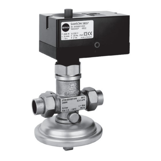
- Page 1 Flow Regulator with Electric Actuator Type 2488 N/5857 Fig. 1 · Type 2488 N/5857 Flow Regulator with Electric Actuator Mounting and Operating Instructions EB 3136 EN Edition December 2011...
-
Page 2: Table Of Contents
Contents Contents Page Design and principle of operation ....4 Installation ....... 5 Mounting position . - Page 3 Safety instructions General safety instructions The flow regulator with electric actuator must be installed, started up and serviced only by skilled or semi-skilled staff in accordance with good engineering practice so that employees and third persons are not exposed to danger.
-
Page 4: Design And Principle Of Operation
(7). The low pressure downstream of the re- The device combines a Type 2488 N Flow striction acts on the low-pressure side of the Regulator and a Type 5857 Electric Actuator. operating diaphragm (9) via a bore in the The electric actuator is attached to the valve valve plug. -
Page 5: Installation
D p of the actuator. Strainer Install a strainer (SAMSON Type 1 NI) up- Mounting the actuator stream of the regulator to prevent sealing particles, weld spatter, pipe scale, and other See Fig. -
Page 6: Electrical Connection
24 V, 50 Hz 0...10 V 0...10 V Electrical connection Electrical connection See Figs. 2 and 3. CAUTION! When laying electric lines, strictly observe the regulations governing the erection of power installations defined by DIN VDE 0100 as well as the regulations specified by your local power supply company. -
Page 7: Operation · Set Point Adjustment
Turn the set point screw (13) clockwise to close the restriction and decrease the flow NOTICE rate. Use the SAMSON manual adjustment Turn the set point screw counterclockwise (1790-8169) to close the restriction. Do not to open the restriction and increase the use the set point screw (13). -
Page 8: Nameplates
Nameplates Made in Germany Nameplate of Type 2488 N Valve Description of the nameplate: Nominal thrust, rated travel actuating time, electrical connection Configuration ID... -
Page 9: Dimensions
Dimensions Dimensions Ø12 ISO 228/1-G ¾ B Ø95 Intermediate insulating piece SW30 SW30 SW30 Welding ends Threaded ends Soldering ends Soldering ends · Dimensions in mm Internal Ø di Length L Fig. 5 · Dimensional drawings (dimensions in mm) EB 3136 EN... -
Page 10: Technical Data
Technical data Technical data Type 5857 Actuator Type 2488 N Valve Rated travel 6 mm Nominal size DN 15 Actuating time for rated travel 20 s Nominal pressure PN 10 Nominal thrust 300 N Max. perm. diff. pressure Dp 4 bar Supply voltage 230 V/24 V (±10 %) -
Page 11: Customer Inquiries
Internet at www.samson.de. To allow SAMSON to find the fault and to have an idea of the installation situation, specify the following details (see nameplate): Type and nominal size of the regulator Model number with index Var.-ID and serial number of actuator... - Page 12 SAMSON AG · MESS- UND REGELTECHNIK Weismüllerstraße 3 · 60314 Frankfurt am Main · Germany Phone: +49 69 4009-0 · Fax: +49 69 4009-1507 EB 3136 EN Internet: http://www.samson.de...
Need help?
Do you have a question about the 2488 N and is the answer not in the manual?
Questions and answers