Page 1
EB 5840 EN Translation of original instructions
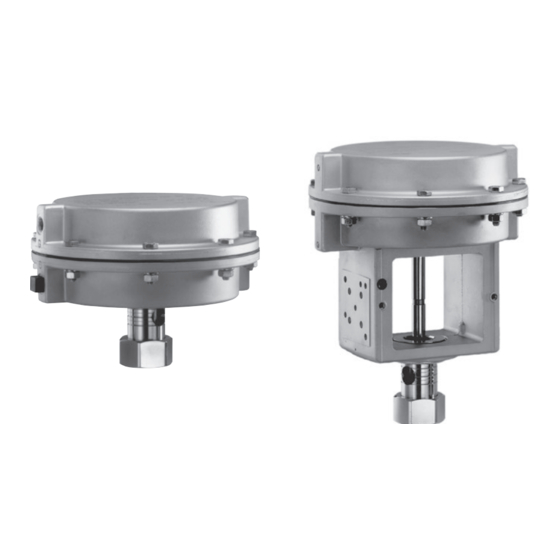
 Type 2780‑1 Type 2780‑2 Type 2780-1 and Type 2780-2 Pneumatic Actuators Actuator area: 120 cm² Edition July 2019...
Page 2
Î For the safe and proper use of these instructions, read them carefully and keep them for later reference. Î If you have any questions about these instructions, contact SAMSON‘s After‑sales Service Department (aftersalesservice@samson.de). The mounting and operating instructions for the devices are included in the scope of delivery.
Contents Safety instructions and measures ..............1-1 Notes on possible severe personal injury ............1‑4 Notes on possible personal injury ..............1‑4 Notes on possible property damage .............1‑6 Markings on the device ................2-1 Actuator nameplate ..................2‑1 Design and principle of operation ...............3-1 Direction of action ..................3‑1 Signal pressure routing ................3‑1 Fail‑safe action ...................3‑3 3.3.1...
Page 4
10.1 Removing the actuator from the valve ............10‑2 10.2 Relieving the spring compression in the actuator ..........10‑2 Repairs ....................11-1 11.1 Returning devices to SAMSON ..............11‑1 Disposal ....................12-1 Appendix ....................13-1 13.1 Tightening torques, lubricants and tools ............13‑1 13.2 Spare parts ....................13‑1 13.3...
SAMSON. SAMSON does not assume any liability for damage resulting from the failure to use the de‑ vice for its intended purpose or for damage caused by external forces or any other external factors.
Page 6
Î Check with the plant operator for details on further protective equipment. Revisions and other modifications Revisions, conversions or other modifications of the product are not authorized by SAMSON. They are performed at the user's own risk and may lead to safety hazards, for example.
Page 7
Safety instructions and measures Referenced standards and regulations According to the ignition risk assessment performed in accordance with EN 13463‑1:2009, section 5.2, the non‑electrical actuators do not have their own potential ignition source even in the rare incident of an operating fault. As a result, they do not fall within the scope of Di‑ rective 2014/34/EU.
Safety instructions and measures 1.1 Notes on possible severe personal injury DANGER Risk of bursting in the actuator. Actuators are pressurized. Improper opening can lead to actuator components burst‑ ing. Î Before starting any work on the actuator, depressurize all plant sections concerned and the actuator.
Page 9
Safety instructions and measures WARNING Risk of personal injury when the actuator vents. The actuator is operated with air. As a result, air is vented during operation. Î Install the control valve in such a way that vent holes are not located at eye level and the actuator does not vent at eye level in the work position Î...
Risk of actuator damage due to the use of unsuitable tools. Certain tools are required to work on the actuator. Î Only use tools approved by SAMSON (u AB 0100). Risk of actuator damage due to the use of unsuitable lubricants. The lubricants to be used depend on the actuator material. Unsuitable lubricants may corrode and damage the surface.
10 Date of manufacture (month and year) SAMSON 2780 Pneumatic Actuator 120 cm² See technical data for ambient temperature Model Var.-ID Serial no. Air supply max. SAMSON AG D-60314 Frankfurt Made in Germany Fig. 2-1: Nameplate of Type 2780 Actuator EB 5840 EN...
Design and principle of operation 3 Design and principle of oper- signal pressure connection on the top dia‑ phragm case. ation The actuator's direction of action can be re‑ The pneumatic actuators are used especially versed (see the 'Operation' section). for attachment to Type 3222 and Type 3213 Valves.
Page 14
Design and principle of operation A38 A39 Fig. 3-1: Type 2780‑1 Actuator stem extends Actuator stem retracts A25-29 Actuator stem Lower actuator section Actuator stem Diaphragm case Vent plug Coupling nut A25‑ Compression spring Metal plate Diaphragm plate Bottom diaphragm case Top diaphragm case Stop bushing Diaphragm Collar nut...
Note to the actuator diaphragm chamber. The listed fail‑safe actions apply to The connecting plate needs to be turned to SAMSON globe valves. align the correct symbol for the fail‑safe ac‑ tion with the marking. 3.3 Fail-safe action When the signal pressure is reduced or the control signal fails, the fail‑safe position of...
Design and principle of operation 3.3.1 Version with direction of Note action "actuator stem ex- Actuators with device index .01 are tends" equipped with new connecting plates. Old and new connecting plates are not inter‑ When the signal pressure is reduced or the changeable.
Page 17
Design and principle of operation Compliance The Type 2780‑1 and Type 2780‑2 Pneu‑ matic Actuators bear the EAC mark of con‑ formity. Dimensions Dimensions (see Fig. 3‑4) Weights Version Weight Type 2780‑1 2 kg Type 2780‑2 3.2 kg Ø168 Ø168 M32 x 1.5 M32 x 1.5 Fig. 3-4: Dimensional drawings EB 5840 EN...
2. Check the shipment for transportation actuator (including the packaging, if ap‑ damage. Report any damage to plicable). SAMSON and the forwarding agent (refer to delivery note). 3. Determine the weight and dimensions of the units to be lifted and transported in Our after‑sales service can provide more...
Î Avoid long storage times. − Make sure the slings can be removed Î Contact SAMSON in case of different from the actuator once it has been storage conditions or long storage peri‑ mounted on the valve.
Page 21
Shipment and on-site transport − Secure the actuator in the stored position against slipping or tipping over. − Do not damage the corrosion protection (paint, surface coatings). Repair any damage immediately. − Protect the actuator against moisture and dirt. Store it at a relative humidity of less than 75 %.
5.2 Mounting the actuator energy in the actuator (e.g. spring com‑ pression). See 'Relieving the spring com‑ SAMSON control valves are delivered ready pression in the actuator' in the 'Removal' for use. In special cases, the valve and actu‑ section.
Risk of actuator damage due to the use of 2. Press the plug together with the plug stem unsuitable tools. firmly into the seat ring. Î Only use tools approved by SAMSON (u AB 0100). 3. Thread the nut (12) downward. 4. Remove the coupling nut (A23) at the actuator.
Mounting 5.2.2 Connecting the air 2. Screw the vent plug into the connection on the bottom diaphragm case. supply The maximum permissible supply pressure is 4 bar in throttling service. How and with which accessories the air sup‑ ply is connected depends on the actuator model and its direction of action.
Page 26
Mounting Vent plug Guide nipple Compression spring Housing Plug Seat Actuator stem A23 Coupling nut Plug stem A40 Bottom diaphragm case Fig. 5-1: Type 2780‑1 Pneumatic Actuator on Type 3213 Valve EB 5840 EN...
WARNING WARNING Î Add any new values to the nameplate. If Crush hazard arising from the moving actu- necessary, contact SAMSON to obtain a ator stem. new nameplate. Î Do not insert hands or finger into the yoke while the air supply is connected to the actuator.
Operation 6.1 Supply pressure in closed- loop operation The Type 2780 Pneumatic Actuator is de‑ signed for a maximum supply pressure of 4 bar. Only apply the signal pressure to the dia‑ phragm chamber of the actuator that does not contain any springs. See the 'Design and principle of operation' section.
Malfunctions 7 Malfunctions 7.1 Troubleshooting Malfunction Possible reasons Recommended action Actuator stem does not Actuator is blocked. Check attachment. move on demand. Unblock the actuator. WARNING! A blocked actuator (e.g. due to seizing up after remaining in the same position for a long time) can suddenly start to move uncontrollably.
Servicing and conversion work 8 Servicing and conversion Î Only open the actuator following the in‑ structions in this document. See 'Reliev‑ work ing the spring compression in the actua‑ The work described in this section is only to tor' in the 'Removal' section. be performed by personnel qualified for the assignment accordingly.
Our after‑sales service can support you in drawing up an inspection and test plan for your plant. NOTICE Risk of actuator damage due to the use of unsuitable tools. Î Only use tools approved by SAMSON (u AB 0100). EB 5840 EN...
Servicing and conversion work 8.2 Preparation for servicing 8.3 Mounting the actuator on or conversion work the valve after servicing or conversion work 1. Lay out the necessary material and tools to have them ready for the intended 1. Mount the actuator and connect the air work.
Page 34
Servicing and conversion work phragm (A48) and metal plate (A38) in‑ 3. Remove the diaphragm plate (A39) to‑ to the bottom diaphragm case (A40). gether with the diaphragm (A48), metal plate (A38) and actuator stem (A1) out 8. Tighten the collar nut (A53). of the bottom diaphragm case (A40).
Servicing and conversion work 10. Fasten the top and bottom diaphragm 4. Remove the diaphragm plate (A39) to‑ cases (A42, A40) together with the nuts gether with the diaphragm (A48) and and bolts. metal plate (A38) from the actuator stem (A1) and place them back on again 8.5 Conversion work turned over.
(A1) and place them back on again Contact your nearest SAMSON subsidiary turned over. or the SAMSON After‑sales Service depart‑ 5. Tighten the collar nut (A53). ment for information on spare parts, lubri‑ 6. Apply a suitable sealant and lubricant to cants and tools.
Decommissioning 9 Decommissioning WARNING WARNING The work described in this section is only to Risk of personal injury due to exhaust air be performed by personnel qualified for the being vented. assignment accordingly. The actuator is operated with air. As a result, air is vented during operation.
Removal 10 Removal WARNING WARNING The work described in this section is only to Risk of personal injury due to exhaust air be performed by personnel qualified for the being vented. assignment accordingly. The actuator is operated with air. As a result, air is vented during operation.
Removal 10.1 Removing the actuator 10.2 Relieving the spring com- from the valve pression in the actuator See Fig. 5‑1 in the 'Mounting' section. 1. Unthread the short nuts and bolts on the diaphragm cases. 1. Removing actuators with "stem ex- tends"...
Further information on returned devices and Î Contact SAMSON's After‑sales Service how they are handled can be found at for repair work. u www.samson.de > Service & Support > After Sales Service. 11.1 Returning devices to SAMSON Defective devices can be returned to SAMSON for repair.
Disposal 12 Disposal Î Observe local, national and internation‑ al refuse regulations. Î Do not dispose of components, lubricants and hazardous substances together with your household waste. EB 5840 EN 12-1...
You can reach our After‑sales Service at aftersalesservice@samson.de. Addresses of SAMSON AG and its subsid- iaries The addresses of SAMSON AG, its subsid‑ iaries, representatives and service facilities worldwide can be found on our website (www.samson.de) or in all SAMSON prod‑...
Need help?
Do you have a question about the 2780-1 and is the answer not in the manual?
Questions and answers