Table of Contents
Advertisement
Quick Links
Advertisement
Table of Contents

Related Manuals for Samson 2357-31


Summary of Contents for Samson 2357-31
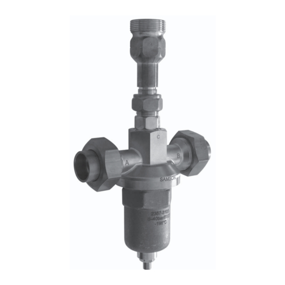
- Page 1 Self-operated Pressure Regulators Pressure Build-up Regulator Type 2357-31 with safety function and integrated pressure relief valve Type 2357-31 with non-return unit · Connections with soldering nipples and ball-type bushings Mounting and Operating Instructions EB 2558 EN Edition March 2010...
-
Page 2: Table Of Contents
Contents Contents Page Design and principle of operation ..... . 4 Process medium, application range ..... 4 Installation . - Page 3 Safety instructions General safety instructions Observe the following instructions on installation, start-up and operation of the regulators for your own safety: The regulator is to be assembled, started up or operated only by trained and experienced personnel familiar with the product. Make sure employees or third persons are not exposed to any danger.
-
Page 4: Design And Principle Of Operation
Design and principle of operation Design and principle of oper- ation Pressure relieve valve Also see Fig. 1 on page 5. The process medium flows from port B to Depending on the direction of flow, the regula- port C. As long as there is no pressure drop tor functions as a pressure build-up regulator across ports B and C, the plug seals off to- with safety function (direction of flow A →... - Page 5 Set point adjuster, Allen key (width across flats SW 6) 6.1 Lock nut (width across flats SW 17) Lower body section Non-return unit (accessories) Soldering nipple with ball-type bushing (accessories) Filter (accessories) Fig. 1 · Functional diagram of Type 2357-31 EB 2558 EN...
-
Page 6: Installation
– Pressure build-up regulator with safety function: from port A to B – Pressure relief valve with non-return unit Type 2357-31 from B to C, port C faces up Fig. 2 · Sample installation EB 2558 EN... -
Page 7: Operation
Operation 1. Loosen the lock nut (6.1) using the SW 17 Operation wrench so far that the set point ad- Also see Fig. 1 on page 5. juster (6) can be moved freely. 2. Determine the difference between the Start-up preset and the desired set point and turn the set point adjuster clockwise or coun- terclockwise for the required number of... -
Page 8: Decommissioning
Check the filters installed in ports A and B (if applicable) and clean them if necessary. If you do not succeed in removing faults or malfunctions yourself, contact SAMSON for support (see section 5). EB 2558 EN... -
Page 9: Customer Service
If malfunctions or defects occur, contact the SAMSON After-sales Service for support. The addresses of SAMSON AG, its subsidiaries, representatives and service facilities world- wide can be found on the Internet at www.samson.de, in a SAMSON product catalog or on the back of these mounting and operating instructions. -
Page 10: Nameplate
Type designation Customer-specific data Fig. 4 · Specifications on the nameplate Technical data Table 2 · Technical data · All pressures in bar (gauge) Type 2357-31 Use with liquid process media Nominal pressure PN 50 coefficient 0.8 for pressure build-up · 0.2 for pressure relief Set point range 1 to 8 bar ·... -
Page 11: Dimensions
Dimensions · Accessories Dimensions Approx. weight: 3.5 kg Fig. 5 · Dimensional drawing Accessories Table 3 · Accessories Accessories Order no. One non-return unit for port C with connection for M40 x 2 ball-type bushing 1400-7092 Two soldering nipples for 28 mm pipe, PN 40, for ports A and B 1400-7090 One soldering nipple for 28 mm pipe, PN 40, for port C (if non-return unit is used) 1400-7300... - Page 12 SAMSON AG · MESS- UND REGELTECHNIK Weismüllerstraße 3 · 60314 Frankfurt am Main · Germany Phone: +49 69 4009-0 · Fax: +49 69 4009-1507 EB 2558 EN Internet: http://www.samson.de...
Need help?
Do you have a question about the 2357-31 and is the answer not in the manual?
Questions and answers