
Related Manuals for Supermicro SuperServer E403-9D-4C-FRDN13+


Summary of Contents for Supermicro SuperServer E403-9D-4C-FRDN13+
- Page 1 SuperServer ® E403-9D-4C-FRDN13+ E403-9D-14CN-FRDN13+ E403-9D-16C-FRDN13+ USER’S MANUAL Revision 1.0...
- Page 2 State of California, USA. The State of California, County of Santa Clara shall be the exclusive venue for the resolution of any such disputes. Supermicro's total liability for all claims will not exceed the price paid for the hardware product.
- Page 3 If you have any questions, please contact our support team at: support@supermicro.com This manual may be periodically updated without notice. Please check the Supermicro website for possible updates to the manual revision level. Secure Data Deletion A secure data deletion tool designed to fully erase all data from storage devices can be found on our website: https://www.supermicro.com/about/policies/disclaimer.cfm?url=/wftp/utility/...
-
Page 4: Table Of Contents
SuperServer E403-9D-4C/14CN/16C-FRDN13+ User's Manual Contents Chapter 1 Introduction 1.1 Overview ..........................7 1.2 System Features ........................9 1.3 Chassis Features .......................10 Control Panel ........................10 Chassis Front ........................11 Chassis Rear ........................12 1.4 Motherboard Layout ......................13 Quick Reference Table ......................15 1.5 Server Installation and Setup .....................18 Unpacking the System ......................18 Warnings and Precautions ....................18 Adding Components to your System ................18... - Page 5 Preface Chapter 3 Motherboard Connections 3.1 Power Connections ......................41 3.2 Headers and Connectors ....................42 3.3 Ports ...........................49 Rear I/O Ports ........................49 Front Control Panel ......................52 3.4 Jumpers ..........................56 Explanation of Jumpers ....................56 3.5 LED Indicators ........................60 Chapter 4 Software 4.1 Driver Installation ........................62 4.2 SuperDoctor 5 ........................64 ®...
- Page 6 Super Micro Computer, Inc. 980 Rock Ave. San Jose, CA 95131 U.S.A. Tel: +1 (408) 503-8000 Fax: +1 (408) 503-8008 Email: marketing@supermicro.com (General Information) support@supermicro.com (Technical Support) Website: www.supermicro.com Europe Address: Super Micro Computer B.V. Het Sterrenbeeld 28, 5215 ML...
-
Page 7: Chapter 1 Introduction
Chapter 1: Introduction Chapter 1 Introduction 1.1 Overview This chapter provides a brief outline of the functions and features of the SuperServer E403-9D-4C/14CN/16C-FRDN13+. Applications for the servers include edge computing, universal customer premise equipment, cloud radio access network, network function virtualization, and software defined wide area network. - Page 8 SuperServer E403-9D-4C/14CN/16C-FRDN13+ User's Manual Motherboard Model Variation Table Motherboard Model X11SDW-4C-TP13F+ X11SDW-14CN-TP13F+ X11SDW-16C-TP13F+ Name Processor Name Intel® Xeon® D-2123IT Intel® Xeon® D-2177NT Intel® Xeon® D-2183IT Number of Cores Number of Threads Processor Base 2.20GHz 1.9GHz 2.2GHz Frequency Max Turbo Frequency 3.00GHz 3.00GHz 3.00GHz...
-
Page 9: System Features
Chapter 1: Introduction 1.2 System Features The table below is an overview of the main features of the SuperServer E403-9D-4C/14CN/16C-FRDN13+. System Features Processors Intel® Xeon® D-2123IT, Intel® Xeon® D-2177NT or Intel® Xeon® D-2183IT Motherboards X11SDW-4C-TP13F+, X11SDW-14CN-TP13F+ or X11SDW-16C-TP13F+, Chassis E403iF-000NBP2 Memory Supports up to 256GB of ECC/non ECC RDIMM or 512GB of ECC LRDIMM DDR4 memory with speeds of up to 2667MHz (D-2177NT) in four DIMM slots... -
Page 10: Chassis Features
SuperServer E403-9D-4C/14CN/16C-FRDN13+ User's Manual 1.3 Chassis Features Control Panel The power button and LEDs located on the control panel are described below. See Chapter 3 for details on the control panel descriptions. Figure 1-1. Control Panel View Control Panel Features Item Features Description... -
Page 11: Chassis Front
Chapter 1: Introduction Chassis Front The illustration below shows the features included on the front of the chassis. Figure 1-2. Chassis Front View Front Chassis Features Item Features Description Power Supplies Redundant 600W DC multi-output power supply modules. USB ports External USB 2.0 Type-A ports. -
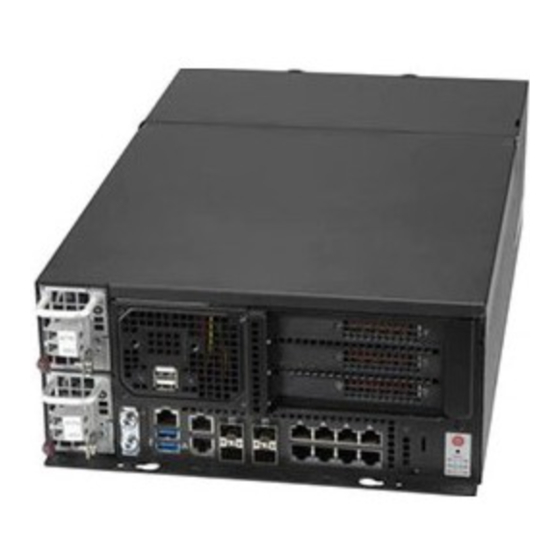
Page 12: Chassis Rear
SuperServer E403-9D-4C/14CN/16C-FRDN13+ User's Manual Chassis Rear The illustration below shows the features included on the rear of the chassis. Figure 1-3. Chassis Rear View Rear Chassis Features Item Features Description Rear Fan Three 80x80mm PWM redundant fans Antenna Ports Five antenna slots Security Slot Kensington®... -
Page 13: Motherboard Layout
Chapter 1: Introduction 1.4 Motherboard Layout Below is a layout of the X11SDW-4C-TP13F+ motherboard with jumper, connector, and LED locations shown. See the table on the following page for descriptions. For detailed descriptions, pinout information, and jumper settings, refer to Chapter 3. LAN10/11 LAN1 LAN12/13... - Page 14 SuperServer E403-9D-4C/14CN/16C-FRDN13+ User's Manual Notes: • See Chapter 2 for detailed information on jumpers, I/O ports, and JF1 front panel connections. Jumpers/LED indicators not indicated are used for testing only. • " " indicates the location of Pin 1. • When LED1 (Onboard Power LED indicator) is on, system power is on.
-
Page 15: Quick Reference Table
Chapter 1: Introduction Quick Reference Table Jumper Description Default Setting M.2 SMBus Enable/Disable Pins 1-2 (Enabled) JBM1 IPMI Share LAN Enable/Disable Open: Enabled (Default) Closed: Disabled JBM2 IPMI Dedicated/Share LAN Enable/Disable Open: Enabled (Default) Closed: Disabled JBT1 CMOS Clear Open: Normal Closed: Clear CMOS C1/JI SMB to PCI-E Slots Enable/Disable... - Page 16 SuperServer E403-9D-4C/14CN/16C-FRDN13+ User's Manual Connector Description JMD2 M.2 Slot B-Key 2242/3042 (USB2.0 / USB3.0 / SATA3.0 / PCI-E x2) JMD3 M.2 Slot E-Key 2230 (USB2.0 / PCI-E x1) JNVI2C1 Non-volatile Memory (NVMe) I C Header JPH1 4-pin HDD Power Connector Power I2C System Management Bus (Power SMB) Header JPV1 12V 8-pin DC Power Connector (Required to provide extra power to the CPU, or as...
- Page 17 Chapter 1: Introduction Figure 1-5. Chipset System Block Diagram Note: This is a general block diagram and may not exactly represent the features on your motherboard. See the System Specifications appendix for the actual specifications of your motherboard.
-
Page 18: Server Installation And Setup
SuperServer E403-9D-4C/14CN/16C-FRDN13+ User's Manual 1.5 Server Installation and Setup The server is shipped with the onboard processor and the motherboard installed in the chassis. Several steps are necessary to begin using your server. You must add memory, mount the hard disk drive, and mount the system in place. Unpacking the System Inspect the box in which the system was shipped and note if it was damaged. -
Page 19: Chapter 2 Maintenance And Component Installation
Chapter 2: Maintenance and Component Installation Chapter 2 Maintenance and Component Installation Note: Maintenance and component installation must be carried out by SUPERMICO service personnel only. Please ensure that the device is connected to a socket/outlet that has a ground/earth connection. This chapter provides instructions on installing and replacing main system components. -
Page 20: Accessing The System
SuperServer E403-9D-4C/14CN/16C-FRDN13+ User's Manual 2.2 Accessing the System The E403iF-000NBP2 features a lockable and segmented top cover. Open the fan cover to access the fans and fan filters. Remove the system cover to access other system components. Remove the hard drive cage, the expansion card module, and the air shroud to access the motherboard. - Page 21 Chapter 2: Maintenance and Component Installation Accessing the Main System 1. Power down the system as described in Section 2.1. 2. Remove one screw on top of the system cover near the I/O panel. See Figure 2-2. 3. Remove two screws on the fan cover if necessary. 4.
- Page 22 SuperServer E403-9D-4C/14CN/16C-FRDN13+ User's Manual Figure 2-3. Slide Cover Off Chassis Caution: Except for short periods of time, do not operate the server without the cover in place. The chassis cover must be in place to allow proper airflow and prevent overheating.
- Page 23 Chapter 2: Maintenance and Component Installation Enabling the Top Cover Lock Function The chassis includes a lock plate that allows the top cover to be locked. 1. Pull the lock plate into a vertical position. 2. Close the fan cover. Make sure the lock plate fits through the slot on the cover. 3.
-
Page 24: Motherboard Components
Use a grounded wrist strap designed to prevent static discharge. • Handle the memory module by its edges only. • Put the memory modules into the antistatic bags when not in use. • Check the Supermicro website for recommended memory modules. -
Page 25: Memory Population Guidelines
Chapter 2: Maintenance and Component Installation Memory Population Guidelines For optimal memory performance, follow the table below when populating memory. Memory Population (Balanced) Total System DIMMA1 DIMMB1 DIMMD1 DIMME1 Memory 16GB 16GB 16GB 24GB 32GB 16GB 16GB 32GB 16GB 16GB 16GB 48GB 16GB... -
Page 26: Dimm Module Population Sequence
SuperServer E403-9D-4C/14CN/16C-FRDN13+ User's Manual DIMM Module Population Sequence When installing memory modules, the DIMM slots should be populated in the following order: DIMMA1, DIMMB1, DIMMD1, DIMME1. • Always use DDR4 DIMM modules of the same type and speed. • Mixed DIMM speeds can be installed. However, all DIMMs will run at the speed of the slowest DIMM. -
Page 27: Dimm Installation
Chapter 2: Maintenance and Component Installation DIMM Installation Caution: Exercise extreme caution when installing or removing memory modules to prevent any possible damage to the DIMMs or slots. Begin by removing power from the system as described in Section 2.1. 1. -
Page 28: Ssd Installation
SuperServer E403-9D-4C/14CN/16C-FRDN13+ User's Manual M.2 SSD Installation The X11SDW-4C/14CN/16C-TP13F+ supports three M.2 SSD connectors. To install an M.2 SSD, first locate the connector and the standoff on the motherboard. 1. Remove the screw from the standoff and set aside. 2. Remove the old M.2 SSD drive. 3. -
Page 29: Motherboard Battery
Chapter 2: Maintenance and Component Installation Motherboard Battery This section describes how to remove and install the motherboard battery. Figure 2-7. Installing the Onboard Battery Replacing the Battery 1. Remove power from the system as described in Section 2.1. 2. Push aside the small clamp that covers the edge of the battery. When the battery is released, lift it out of the holder. -
Page 30: Chassis Components
SuperServer E403-9D-4C/14CN/16C-FRDN13+ User's Manual 2.4 Chassis Components Installing the Storage Drive(s) The E403iF-000NBP2 can accommodate up to four fixed 2.5" storage drives that are installed to a hard drive cage and then inserted into the chassis. Screw Hard Drive Cage Plastic Handles Screw Figure 2-8. - Page 31 Chapter 2: Maintenance and Component Installation Installing Hard Drives The hard drive cage must be removed from the chassis before installing the hard drives. 1. Make sure there is no power to the system as described in Section 2.1 and remove the chassis cover.
-
Page 32: Expansion Cards
SuperServer E403-9D-4C/14CN/16C-FRDN13+ User's Manual Expansion Cards The E403-9D-4C/14CN/16C-FRDN13+ supports up to three PCI-E slots on the riser card. Follow the table printed on the riser card to set the JSEL jumper. The IIO configurations may also need to be set in the BIOS. Installing Expansion Cards 1. - Page 33 Chapter 2: Maintenance and Component Installation Expansion Card Module Expansion Card (optional) Figure 2-11. Expansion Card Module Removed 7. Connect the power cable to the expansion card if necessary. 8. Reinstall the expansion card module. 9. Reinstall the chassis top cover, reconnect the AC power cord and power up the system.
-
Page 34: System Cooling
SuperServer E403-9D-4C/14CN/16C-FRDN13+ User's Manual System Cooling The E403iF-000NBP2 includes three hot-swappable 8-cm fans. Installing or Replacing the System Fan 1. Access the fans as described in Section 2.2. 2. Press the latch at the side of the fan. See the figure below. 3. - Page 35 Chapter 2: Maintenance and Component Installation Installing or Replacing the Fan Filters The system supports three fan filters that can be removed and cleaned. Power to the system can remain on while the the fan filters are removed or installed. 1.
- Page 36 SuperServer E403-9D-4C/14CN/16C-FRDN13+ User's Manual Installing the Air Shroud The air shroud directs airflow from two of the fans to the center of the motherboard. 1. If you are installing expansion cards that require power from the power supply, you must cut a hole to route the power cable from the power supply to the expansion module.
-
Page 37: Mounting On A Surface
Chapter 2: Maintenance and Component Installation Mounting on a Surface The E403iF-000NBP2 can be mounted directly on a surface using the mounting brackets and mounting screws or nails. The following procedure describes how to mount the system to a sturdy surface. Use screws or nails of sufficient strength to support the weight of the system. Mounting the Chassis 1. - Page 38 SuperServer E403-9D-4C/14CN/16C-FRDN13+ User's Manual 2. Decide on an orientation to mount the server. The server can only be mounted with the I/O panel facing left or right. 76.20mm 420mm I/O Facing Left 76.20mm 420mm I/O Facing Right Figure 2-16. Possible Mounting Orientations...
- Page 39 Chapter 2: Maintenance and Component Installation 3. Mark two keyhole spots on the surface where the server will be mounted. The two keyholes for each orientation are circled in red. See Figure 2-16. 4. Install the two keyhole screws or nails. 5.
-
Page 40: Power Supply
Replacement units can be ordered directly from Supermicro (see contact information in the Preface). The hot-swap capability of the power supply modules allows you to replace the failed module without powering down the system. -
Page 41: Chapter 3 Motherboard Connections
Chapter 3: Motherboard Connections Chapter 3 Motherboard Connections This section describes the connections on the motherboard and provides pinout definitions. Note that depending on how the system is configured, not all connections are required. The LEDs on the motherboard are also described here. A motherboard layout indicating component locations may be found in Chapter 1. -
Page 42: Headers And Connectors
SuperServer E403-9D-4C/14CN/16C-FRDN13+ User's Manual 3.2 Headers and Connectors Fan Headers The X11SDW-4C/14CN/16C-TP13F+ has six 4-pin fan headers (FAN1 - FAN4, FANA, FANB). These headers are backwards-compatible with the traditional 3-pin fans. However, fan speed control is available for 4-pin fans only by Thermal Management via the IPMI 2.0 interface. This motherboard supports dual cooling zone. - Page 43 Chapter 3: Motherboard Connections SATA Ports The X11SDW-4C/14CN/16C-TP13F+ motherboard has four S-SATA 3.0 ports. Refer to the tables below for pin definitions. SATA ports provide serial-link signal connections, which are faster than the connections of Parallel ATA. SATA 3.0 Port Pin Definitions Pin# Signal...
- Page 44 SuperServer E403-9D-4C/14CN/16C-FRDN13+ User's Manual VGA Header Connect a 16-pin VGA extension cable to JVGA1 for a VGA connecton. VGA Header Pin Definitions Pin# Definition Pin# Definition VGA_RED VGA_GRE VGA_BLE VGA_DET (GND) DDCSDA HSYNC VSYNC DDCSCL Intel RAID Key Header The JRK1 header allows the user to enable RAID functions. Refer to the table below for pin definitions.
- Page 45 Chapter 3: Motherboard Connections General Purpose I/O Header The JGP1 (General Purpose Input/Output) header is a general purpose I/O expander on a pin header via the SMBus. Refer to the table below for pin definitions. GPIO Header Pin Definitions Pin# Definition Pin# Definition...
- Page 46 Clock NVMe I C Header JNVI C1 is a management header for the Supermicro AOC NVMe PCI-E peripheral cards. Connect a corresponding I C cable to this header. Refer to the table below for pin definitions. NVMe I C Header...
- Page 47 Chapter 3: Motherboard Connections LAN Port Activity LED JLANLED1 is the activity LED for LAN1, JLANLED2 is the activity LED for LAN2 - LAN5, and JLANLED3 is the activity LED for LAN6 - LAN9. JLANLED1 LAN Activity LED Pin Definitions Pin# Definition P3V3 Dual...
- Page 48 SuperServer E403-9D-4C/14CN/16C-FRDN13+ User's Manual Software-Defined Pins (SDP) JSDP1, JSDP2, and JSDP3 are software-defined pins that can be used to support IEEE 1588 auxiliary devices and other hardware or software-control purposes. These pins can be configured to function as standard inputs or General-Purpose Interrupt (GPI) input or output pins.
-
Page 49: Ports
Chapter 3: Motherboard Connections 3.3 Ports Rear I/O Ports See Figure 3-1 below for the locations and descriptions of the various I/O ports on the front of the motherboard. PCB EDGE LED2 PRESS FIT PRESS FIT JUIDB1 JSXB1A LED3 COM1 USB 4/5(3.0) LAN 2/3/4/5/6/7/8/9 LAN 1... - Page 50 SuperServer E403-9D-4C/14CN/16C-FRDN13+ User's Manual LAN Ports The motherboard has 13 LAN ports. LAN1 – LAN9 are 1G ports and LAN10 - LAN13 are 10G SFP+ ports. In addition to the LAN ports, the motherboard offers a dedicated IPMI LAN port. Refer to the table below for the pin definitions. LAN Port Pin Definition Pin#...
- Page 51 Note: UID can also be triggered via IPMI on the motherboard. For more information on IPMI, please refer to the IPMI User's Guide posted on our website at http://www.supermicro.com UID LED Pin Definitions...
-
Page 52: Front Control Panel
JF1 contains header pins for various buttons and indicators that are normally located on a control panel at the front of the chassis. These connectors are designed specifically for use with Supermicro chassis. See the figure below for the descriptions of the front control panel buttons and LED indicators. - Page 53 Chapter 3: Motherboard Connections Power Button The Power Button connection is located on pins 1 and 2 of JF1. Momentarily contacting both pins will power on/off the system. This button can also be configured to function as a sus- pend button (with a setting in the BIOS - see Chapter 4). To turn off the power in the suspend mode, press the button for at least seconds seconds.
- Page 54 SuperServer E403-9D-4C/14CN/16C-FRDN13+ User's Manual Overheat (OH)/Fan Fail Connect an LED cable to OH/Fan Fail connections on pins 7 and 8 of JF1 to provide warnings for chassis overheat and fan failure. Refer to the table below for pin definitions. OH/Fan Fail Indicator Status State Definition...
- Page 55 Chapter 3: Motherboard Connections Power LED The Power LED connection is located on pins 15 and 16 of JF1. Refer to the table below for pin definitions. Power LED Pin Definitions (JF1) Pins Definition +3.3V PWR LED...
-
Page 56: Jumpers
SuperServer E403-9D-4C/14CN/16C-FRDN13+ User's Manual 3.4 Jumpers Explanation of Jumpers To modify the operation of the motherboard, jumpers are used to choose between optional settings. Jumpers create shorts between two pins to change the function associated with it. Pin 1 is identified with a square solder pad on the printed circuit board. See the motherboard layout page for jumper locations. - Page 57 Chapter 3: Motherboard Connections SMBus to PCI-E Slots Jumpers JI2C1 and JI2C2 allow you to connect the System Management Bus (I2C) to the PCI-E slots. Both jumpers must be set to the same setting (JI2C1 controls the clock and JI2C2 controls the data). SMBus to PCI-E Slots Jumper Settings Jumper Setting...
- Page 58 SuperServer E403-9D-4C/14CN/16C-FRDN13+ User's Manual Watch Dog JJWD1 controls the Watch Dog function. Watch Dog is a monitor that can reboot the system when a software application hangs. Jumping pins 1-2 will cause Watch Dog to reset the system if an application hangs. Jumping pins 2-3 will generate a non-maskable interrupt signal for the application that hangs.
- Page 59 Chapter 3: Motherboard Connections IPMI Share LAN Enable/Disable Set the JBM1 jumper to enabled to share i210 LAN with IPMI. IPMI Share LAN Enable/Disable Jumper Settings Jumper Setting Definition Pins 1-2 (Open) Enabled (Default) Pins 1-2 (Short) Disabled IPMI Dedicated/Share LAN Enable/Disable Use JBM2 to enable or disable the dedicated IPMI LAN port.
-
Page 60: Led Indicators
SuperServer E403-9D-4C/14CN/16C-FRDN13+ User's Manual 3.5 LED Indicators LAN LEDs Thirteen LAN ports (LAN1 - LAN13) are located on the I/O back panel. Each LAN port has two LEDs. The yellow LED indicates activity, while the other Link LED may be green, amber, or off to indicate the speed of the connection. - Page 61 Chapter 3: Motherboard Connections Overheat/Power Fail/Fan Fail LED When the light for LED3 is solid red, it means overheating. When the LED is blinking red, it means a power failure or fan failure. Overheat/Power Fail/Fan Fail LED Indicator LED Color Definition Solid Red Overheat...
-
Page 62: Chapter 4 Software
The Supermicro website contains drivers and utilities for your system at https://www. supermicro.com/wftp. Some of these must be installed, such as the chipset driver. After accessing the website, go into the CDR_Images directory and locate the ISO file for your motherboard. Download this file to create a DVD of the drivers and utilities it contains. - Page 63 Chapter 4: Software Figure 4-1. Driver & Tool Installation Screen Note: Click the icons showing a hand writing on paper to view the readme files for each item. Click the computer icons to the right of these items to install each item (from top to the bottom) one at a time.
-
Page 64: Superdoctor ® 5
4.2 SuperDoctor ® The Supermicro SuperDoctor 5 is a program that functions in a command-line or web-based interface for Windows and Linux operating systems. The program monitors such system health information as CPU temperature, system voltages, system power consumption, fan speed, and provides alerts via email or Simple Network Management Protocol (SNMP). -
Page 65: Chapter 5 Uefi Bios
Chapter 5: UEFI BIOS Chapter 5 UEFI BIOS 5.1 Introduction This chapter describes the AMIBIOS™ Setup utility for the X11SDW-4C/14CN/16C-TP13F+ motherboard. The BIOS is stored on a chip and can be easily upgraded using a flash program. Note: Due to periodic changes to the BIOS, some settings may have been added or deleted and might not yet be recorded in this manual. -
Page 66: Main Setup
Note: The time is in the 24-hour format. For example, 5:30 P.M. appears as 17:30:00. The date's default value is the BIOS build date after RTC reset. Supermicro X11SDW-16C-TP13F+ BIOS Version This feature displays the version of the BIOS ROM used in the system. -
Page 67: Advanced
Chapter 5: UEFI BIOS 5.3 Advanced Use this menu to configure advanced settings. Warning: Take caution when changing the Advanced settings. An incorrect value, a very high DRAM frequency or an incorrect BIOS timing setting may cause the system to malfunction. When this occurs, restore to default manufacturer settings. - Page 68 Super E403-9D-4C/14CN/16C-FRDN13+ User's Manual INT19 Trap Response Interrupt 19 is the software interrupt that handles the boot disk function. When this feature is set to Immediate, the ROM BIOS of the host adaptors will "capture" Interrupt 19 at boot up immediately and allow the drives that are attached to these host adaptors to function as bootable disks.
- Page 69 Chapter 5: UEFI BIOS • Processor Max Ratio • Processor Min Ratio • Microcode Revision • L1 Cache RAM • L2 Cache RAM • L3 Cache RAM • Processor 0 Version Hyper-Threading (ALL) Select Enabled to support Intel Hyper-threading Technology to enhance CPU performance. The options are Disable and Enable.
- Page 70 Super E403-9D-4C/14CN/16C-FRDN13+ User's Manual Adjacent Cache Prefetch (Available when supported by the CPU) The CPU prefetches the cache line for 64 bytes if this feature is set to Disabled. The CPU prefetches both cache lines for 128 bytes as comprised if this feature is set to Enable. The options are Enable and Disable.
- Page 71 Chapter 5: UEFI BIOS *If the feature above is set to BIOS Controls EPB, the following features will be available for configuration: ENERGY_PERF_BIAS_CFG Mode The Energy Perfomance BIAS (EPB) feature allows you to configure CPU power and per- fomance settings. Select Maximum Performance to set the highest performance. Select Performance to optimize performance over energy efficiecy.
- Page 72 Super E403-9D-4C/14CN/16C-FRDN13+ User's Manual Turbo Mode This feature will enable dynamic control of the processor, allowing it to run above stock frequency. The options are Disable and Enable. Hardware PM State Control Hardware P-States This setting allows you to select between OS and hardware-controlled P-states. Select- ing Native Mode allows the OS to choose a P-state.
- Page 73 Chapter 5: UEFI BIOS CPU T State Control Software Controlled T-States Use this feature to enable Software Controlled T-States. The options are Disable and Enable. Chipset Configuration Warning: Setting the wrong values in the sections below may cause the system to malfunction. North Bridge Configuration ...
- Page 74 Super E403-9D-4C/14CN/16C-FRDN13+ User's Manual Memory RAS Configuration Static Virtual Lockstep Mode Select Enable to run the system's memory channels in lockstep mode to minimize memory access latency. The options are Disable and Enable. Mirror Mode This feature allows memory to be mirrored between two channels, providing 100% redundancy.
- Page 75 Chapter 5: UEFI BIOS Patrol Scrub Patrol Scrub is a process that allows the CPU to correct correctable memory errors detected on a memory module and send the correction to the requestor (the original source). When this feature is set to Enable, the IO hub will read and write back one cache line every 16K cycles if there is no delay caused by internal processing.
- Page 76 Super E403-9D-4C/14CN/16C-FRDN13+ User's Manual PCI-E Port Link Status This feature shows the status of the device plugged into this slot. PCI-E Port Link Max This feature shows the status of the device plugged into this slot. PCI-E Port Link Speed This feature shows the status of the device plugged into this slot.
- Page 77 Chapter 5: UEFI BIOS *If the feature above is set to Enable, the five features below will be available for configuration: Interrupt Remapping Use this feature to enable Interrupt Remapping support, which detects and controls external interrupt requests. The options are Enable and Disable. PassThrough DMA Use this feature to allow devices such as network cards to access the system memory without using a processor.
- Page 78 Super E403-9D-4C/14CN/16C-FRDN13+ User's Manual RSC-R1UW-2E16 SLOT1 VMD (Available when detected by the system) Select Enable to use the Intel Volume Management Device Technology for this spe- cific root port. The options are Disable and Enable. Hot Plug Capable (Available when the device is detected by the system) Use this feature to enable hot plug support for PCIe root ports 1A~1D.
- Page 79 Chapter 5: UEFI BIOS PCI-E Completion Timeout Disable Use this feature to enable PCI-E Completion Timeout support for electric tuning. The options are Yes, No, and Per-Port. South Bridge Configuration The following South Bridge information will display: • USB Module Version •...
- Page 80 Super E403-9D-4C/14CN/16C-FRDN13+ User's Manual PCH SATA Configuration When this submenu is selected, the AMI BIOS automatically detects the presence of the SATA devices that are supported by the Intel PCH chip and displays the following features: SATA Controller Use this feature to enable or disable the onboard SATA controller supported by the Intel PCH chip.
- Page 81 Chapter 5: UEFI BIOS PCH sSATA Configuration When this submenu is selected, the AMI BIOS automatically detects the presence of the SATA devices that are supported by the Intel PCH chip and displays the following features: sSATA Controller This feature enables or disables the onboard sSATA controller supported by the Intel PCH chip.
- Page 82 Super E403-9D-4C/14CN/16C-FRDN13+ User's Manual Port 0 ~ Port 4 Hot Plug Set this feature to Enable for hot plug support, which will allow the user to replace a SATA drive without shutting down the system. The options are Disable and Enable. Port 0 ~ Port 4 Spin Up Device Set this feature to enable or disable the PCH to initialize the device.
- Page 83 Chapter 5: UEFI BIOS MMCFG Base Use this feature to select the low base address for PCI-E adapters to increase base memory. The options are 1G, 1.5G, 1.75G, 2G, 2.25G, and 3G. NVMe Firmware Source Use this feature to select the NVMe firmware to support booting. The default option, Vendor Defined Firmware, is pre-installed on the drive and may resolve errata or enable innovative functions for the drive.
- Page 84 Super E403-9D-4C/14CN/16C-FRDN13+ User's Manual Onboard LAN Option ROM Type Use this feature to select which firmware type to be loaded for onboard LAN devices. The options Legacy and EFI. Select Legacy to display and configure the Onboard LAN1 - LAN13 Option ROM features.
- Page 85 Chapter 5: UEFI BIOS Super IO Configuration Super IO Chip AST2500 Serial Port 1 Configuration Serial Port 1 Select Enabled to enable the onboard serial port specified by the user. The options are Enabled and Disabled. Enable this feature for the next two features to display and only the Change Settings feature is available for configuration.
- Page 86 Super E403-9D-4C/14CN/16C-FRDN13+ User's Manual Serial Port 2 Attribute Select SOL to use COM Port 2 as a Serial Over LAN (SOL) port for console redirection. The options are SOL and COM. Serial Port Console Redirection COM1 Console Redirection Select Enabled to enable COM Port 1 for Console Redirection, which will allow a client machine to be connected to a host machine at a remote site for networking.
- Page 87 Chapter 5: UEFI BIOS Stop Bits A stop bit indicates the end of a serial data packet. Select 1 Stop Bit for standard serial data communication. Select 2 Stop Bits if slower devices are used. The options are 1 and 2. Flow Control Use this feature to set the flow control for Console Redirection to prevent data loss caused by buffer overflow.
- Page 88 Super E403-9D-4C/14CN/16C-FRDN13+ User's Manual Console Redirection Settings Use this feature to specify how the host computer will exchange data with the client computer, which is the remote computer used by the user. SOL/COM2 Terminal Type Use this feature to select the target terminal emulation type for Console Redirection. Select VT100 to use the ASCII Character set.
- Page 89 Chapter 5: UEFI BIOS VT-UTF8 Combo Key Support Select Enabled to enable VT-UTF8 Combination Key support for ANSI/VT100 terminals. The options are Disabled and Enabled. Recorder Mode Select Enabled to capture the data displayed on a terminal and send it as text messages to a remote server.
- Page 90 Super E403-9D-4C/14CN/16C-FRDN13+ User's Manual Console Redirection Settings This feature allows you to specify how the host computer will exchange data with the client computer, which is the remote computer used by the user. Out-of-Band Mgmt Port The feature selects a serial port in a client server to be used by the Microsoft Windows Emergency Management Services (EMS) to communicate with a remote host server.
- Page 91 Chapter 5: UEFI BIOS WHEA Support Select Enabled to support the Windows Hardware Error Architecture (WHEA) platform and provide a common infrastructure for the system to handle hardware errors within the Windows OS environment in order to reduce system crashes and enhance system recovery and health monitoring.
- Page 92 Use this feature to disable or enable endorsement hierarchy for privacy control. The options are Disabled and Enabled. SMCI BIOS-Based TPM Provision Support Use feature to enable the Supermicro TPM Provision support. The options are Disabled and Enabled. TXT Support Intel TXT (Trusted Execution Technology) helps protect against software-based attacks and ensures protection, confidentiality and integrity of data stored or created on the system.
-
Page 93: Event Logs
Chapter 5: UEFI BIOS 5.4 Event Logs Use this menu to configure event log settings. Change SMBIOS Event Log Settings Enabling/Disabling Options SMBIOS Event Log Change this feature to enable or disable all features of the SMBIOS Event Logging during system boot. - Page 94 Super E403-9D-4C/14CN/16C-FRDN13+ User's Manual SMBIOS Event Log Standard Settings Log System Boot Event Select Enabled to log system boot events. The options are Enabled and Disabled. MECI (Multiple Event Count Increment) Enter the increment value for the multiple event counter. Enter a number between 1 to 255. The default setting is 1.
-
Page 95: Ipmi
Chapter 5: UEFI BIOS 5.5 IPMI Use this menu to configure Intelligent Platform Management Interface (IPMI) settings. BMC Firmware Revision This feature displays the IPMI firmware revision used in your system. IPMI STATUS This feature displays the status of the IPMI firmware installed in your system. System Event Log Enabling/Disabling Options SEL Components... - Page 96 Super E403-9D-4C/14CN/16C-FRDN13+ User's Manual When SEL is Full This feature allows you to determine what the BIOS should do when the system event log is full. Select Erase Immediately to erase all events in the log when the system event log is full.
- Page 97 Chapter 5: UEFI BIOS Gateway IP Address This feature displays the Gateway IP address for this computer. This should be in decimal and in dotted quad form (i.e., 192.168.10.253). VLAN This feature is configurable if the Update IPMI LAN Configuration feature is set to Yes. Use this feature to enable or disable the IPMI VLAN function.
- Page 98 IPMI features. The Disable option is for applications that require faster power on time without using Supermicro Update Manager (SUM) or extended IPMI features. The BMC network configuration in the BIOS setup will also be invalid when IPMI Extended Instruction is disabled.
-
Page 99: Security
Chapter 5: UEFI BIOS 5.6 Security Use this menu to configure the security settings. Administrator Password Use this feature to set the administrator password which is required to enter the BIOS setup utility. The length of the password should be from three to 20 characters long. Password Check Select Setup for the system to check for a password at Setup. - Page 100 Super E403-9D-4C/14CN/16C-FRDN13+ User's Manual Secure Boot Mode This feature allows you to select the desired secure boot mode for the system. The options are Standard and Custom. *If Secure Boot Mode is set to Custom, Key Management features are available for configuration: CSM Support This feature is for manufacturing debugging purposes.
- Page 101 Chapter 5: UEFI BIOS Key Exchange Keys (KEK) Update Select Yes to load a factory default KEK or No to load from a file on an external media. Append Select Yes to add the KEK from the manufacturer's defaults list to the existing KEK. Select No to load the KEK from a file.
-
Page 102: Boot
Super E403-9D-4C/14CN/16C-FRDN13+ User's Manual 5.7 Boot Use this menu to configure boot settings: Boot mode select Use this feature to select the boot mode. The options are Legacy, UEFI, and Dual. Legacy to EFI Support Select Enabled to boot EFI OS support after Legacy boot order has failed. The options are Disabled and Enabled. - Page 103 Chapter 5: UEFI BIOS • Boot Option #11 • Boot Option #12 • Boot Option #13 • Boot Option #14 • Boot Option #15 • Boot Option #16 • Boot Option #17 Add New Boot Option Use this feature to add a new boot option to system boot priority features. ...
-
Page 104: Save & Exit
Super E403-9D-4C/14CN/16C-FRDN13+ User's Manual 5.8 Save & Exit Use this menu to configure save and exit settings. Save Options Discard Changes and Exit Select this feature to quit the BIOS Setup without making any permanent changes to the system configuration and reboot the computer. Select Discard Changes and Exit from the Exit menu and press <Enter>. - Page 105 Chapter 5: UEFI BIOS Save as User Defaults To set this feature, select Save as User Defaults from the Exit menu and press <Enter>. This enables the user to save any changes to the BIOS setup for future use. Restore User Defaults To set this feature, select Restore User Defaults from the Exit menu and press <Enter>.
-
Page 106: Appendix A Bios Error Codes
When BIOS performs the Power On Self Test, it writes checkpoint codes to I/O port 0080h. If the computer cannot complete the boot process, a diagnostic card can be attached to the computer to read I/O port 0080h (Supermicro p/n AOC-LPC80-20). For information on AMI updates, please refer to http://www.ami.com/products/. -
Page 107: Appendix B Standardized Warning Statements For Dc Systems
Supermicro's Technical Support department for assistance. Only certified technicians should attempt to install or configure components. Read this appendix in its entirety before installing or configuring components in the Supermicro chassis. These warnings may also be found on our website at http://www.supermicro.com/about/... - Page 108 Appendix B: Standardized Warning Statements Warnung WICHTIGE SICHERHEITSHINWEISE Dieses Warnsymbol bedeutet Gefahr. Sie befinden sich in einer Situation, die zu Verletzungen führen kann. Machen Sie sich vor der Arbeit mit Geräten mit den Gefahren elektrischer Schaltungen und den üblichen Verfahren zur Vorbeugung vor Unfällen vertraut. Suchen Sie mit der am Ende jeder Warnung angegebenen Anweisungsnummer nach der jeweiligen Übersetzung in den übersetzten Sicherheitshinweisen, die zusammen mit diesem Gerät ausgeliefert wurden.
- Page 109 SuperServer E403-9D-4C/14CN/16C-FRDN13+ User's Manual . ٌ ا ك ً ف حالة و ٌ يك أى تتسبب ف اصابة جسذ ة ٌ هذا الزهز ع ٌ خطز !تحذ ز قبل أى تعول عىل أي هعذات،يك عىل علن بالوخاطز ال ا ٌجوة عي الذوائز ٍ...
- Page 110 Appendix B: Standardized Warning Statements Warnung Vor dem Anschließen des Systems an die Stromquelle die Installationsanweisungen lesen. ¡Advertencia! Lea las instrucciones de instalación antes de conectar el sistema a la red de alimentación. Attention Avant de brancher le système sur la source d'alimentation, consulter les directives d'installation. .יש...
- Page 111 SuperServer E403-9D-4C/14CN/16C-FRDN13+ User's Manual Warnung Dieses Produkt ist darauf angewiesen, dass im Gebäude ein Kurzschluss- bzw. Überstromschutz installiert ist. Stellen Sie sicher, dass der Nennwert der Schutzvorrichtung nicht mehr als: 60VDC, 20A beträgt. ¡Advertencia! Este equipo utiliza el sistema de protección contra cortocircuitos (o sobrecorrientes) del edificio.
- Page 112 Appendix B: Standardized Warning Statements Power Disconnection Warning Warning! The system must be disconnected from all sources of power and the power cord removed from the power supply module(s) before accessing the chassis interior to install or remove system components. 電源切断の警告...
- Page 113 SuperServer E403-9D-4C/14CN/16C-FRDN13+ User's Manual يجب فصم اننظاو من جميع مصادر انطاقت وإ ز انت سهك انكهرباء من وحدة امداد انطاقت قبم انىصىل إىن امنناطق انداخهيت نههيكم نتثبيج أو إ ز انت مكىناث الجهاز 경고! 시스템에 부품들을 장착하거나 제거하기 위해서는 섀시 내부에 접근하기 전에 반드시 전원 공급장치로부터...
- Page 114 Appendix B: Standardized Warning Statements Attention Il est vivement recommandé de confier l'installation, le remplacement et la maintenance de ces équipements à des personnels qualifiés et expérimentés. !אזהרה .צוות מוסמך בלבד רשאי להתקין, להחליף את הציוד או לתת שירות עבור הציוד واملدربيه...
- Page 115 SuperServer E403-9D-4C/14CN/16C-FRDN13+ User's Manual Warnung Diese Einheit ist zur Installation in Bereichen mit beschränktem Zutritt vorgesehen. Der Zutritt zu derartigen Bereichen ist nur mit einem Spezialwerkzeug, Schloss und Schlüssel oder einer sonstigen Sicherheitsvorkehrung möglich. ¡Advertencia! Esta unidad ha sido diseñada para instalación en áreas de acceso restringido. Sólo puede obtenerse acceso a una de estas áreas mediante la utilización de una herramienta especial, cerradura con llave u otro medio de seguridad.
- Page 116 Appendix B: Standardized Warning Statements Battery Handling Warning! There is the danger of explosion if the battery is replaced incorrectly. Replace the battery only with the same or equivalent type recommended by the manufacturer. Dispose of used batteries according to the manufacturer's instructions 電池の取り扱い...
- Page 117 SuperServer E403-9D-4C/14CN/16C-FRDN13+ User's Manual هناك خطر من انفجار يف حالة اسحبذال البطارية بطريقة غري صحيحة فعليل اسحبذال البطارية فقط بنفس النىع أو ما يعادلها مام أوصث به الرشمة املصنعة جخلص من البطاريات املسحعملة وفقا لحعليامت الرشمة الصانعة 경고! 배터리가 올바르게 교체되지 않으면 폭발의 위험이 있습니다. 기존 배터리와 동일하거나 제 조사에서...
- Page 118 Appendix B: Standardized Warning Statements ¡Advertencia! Puede que esta unidad tenga más de una conexión para fuentes de alimentación. Para cortar por completo el suministro de energía, deben desconectarse todas las conexiones. Attention Cette unité peut avoir plus d'une connexion d'alimentation. Pour supprimer toute tension et tout courant électrique de l'unité, toutes les connexions d'alimentation doivent être débranchées.
- Page 119 SuperServer E403-9D-4C/14CN/16C-FRDN13+ User's Manual Backplane Voltage Warning! Hazardous voltage or energy is present on the backplane when the system is operating. Use caution when servicing. バックプレーンの電圧 システムの稼働中は危険な電圧または電力が、 バックプレーン上にかかっています。 修理する際には注意ください。 警告 当系统正在进行时,背板上有很危险的电压或能量,进行维修时务必小心。 警告 當系統正在進行時,背板上有危險的電壓或能量,進行維修時務必小心。 Warnung Wenn das System in Betrieb ist, treten auf der Rückwandplatine gefährliche Spannungen oder Energien auf.
- Page 120 Appendix B: Standardized Warning Statements هناك خطز مه التيار الكهزبايئ أوالطاقة املىجىدة عىل اللىحة عندما يكىن النظام يعمل كه حذ ر ا عند خدمة هذا الجهاس 경고! 시스템이 동작 중일 때 후면판 (Backplane)에는 위험한 전압이나 에너지가 발생 합니다. 서비스 작업 시 주의하십시오. Waarschuwing Een gevaarlijke spanning of energie is aanwezig op de backplane wanneer het systeem in gebruik is.
- Page 121 SuperServer E403-9D-4C/14CN/16C-FRDN13+ User's Manual תיאום חוקי החשמל הארצי !אזהרה .התקנת הציוד חייבת להיות תואמת לחוקי החשמל המקומיים והארציים تركيب املعدات الكهربائية يجب أن ميتثل للقىاويه املحلية والىطىية املتعلقة بالكهرباء 경고! 현 지역 및 국가의 전기 규정에 따라 장비를 설치해야 합니다. Waarschuwing Bij installatie van de apparatuur moet worden voldaan aan de lokale en nationale elektriciteitsvoorschriften.
- Page 122 Appendix B: Standardized Warning Statements Attention La mise au rebut ou le recyclage de ce produit sont généralement soumis à des lois et/ou directives de respect de l'environnement. Renseignez-vous auprès de l'organisme compétent. סילוק המוצר !אזהרה .סילוק סופי של מוצר זה חייב להיות בהתאם להנחיות וחוקי המדינה التخلص...
- Page 123 SuperServer E403-9D-4C/14CN/16C-FRDN13+ User's Manual Warnung Gefährlich Bewegende Teile. Von den bewegenden Lüfterblätter fern halten. Die Lüfter drehen sich u. U. noch, wenn die Lüfterbaugruppe aus dem Chassis genommen wird. Halten Sie Finger, Schraubendreher und andere Gegenstände von den Öffnungen des Lüftergehäuses entfernt.
- Page 124 Appendix B: Standardized Warning Statements DC Power Supply Warning! When stranded wiring is required, use approved wiring terminations, such as closedloop or spade-type with upturned lugs. These terminations should be the appropriate size for the wires and should clamp both the insulation and conductor. 警告...
- Page 125 SuperServer E403-9D-4C/14CN/16C-FRDN13+ User's Manual وأ ةقلغم ةقلح لثم ،اهيلع ةقفاوملا ءاهنإ كالسألا مادختساو ،لبسلا مهب تعطقت نيذلا كالسألا ابولطم نوكي امدنع بجيو كالسألل بسانملا مجحلا نوكي تاءاهنإلا هذهل يغبنيو .ةبولقم تاورعلا عم عونلا ةيقيقحلا اهئامسأب ءايشألا .لصومو لزعلا نم لك حبك 주의! 꼬인...
- Page 126 Appendix B: Standardized Warning Statements Warnung Vor Ausführung der folgenden Vorgänge ist sicherzustellen, daß die Gleichstromschaltung keinen Strom erhält. ¡Advertencia! Antes de proceder con los siguientes pasos, comprobar que la alimentación del circuito de corriente continua (CC) esté cortada (OFF). Attention Avant de pratiquer l'une quelconque des procédures ci-dessous, vérifier que le circuit en courant continu n'est plus sous tension.
- Page 127 SuperServer E403-9D-4C/14CN/16C-FRDN13+ User's Manual Hazardous Voltage or Energy Present on DC Power Terminals Warning! Hazardous voltage or energy may be present on DC power terminals. Always replace cover when terminals are not in service. Be sure uninsulated conductors are not accessible when cover is in place. 警告...
- Page 128 Appendix B: Standardized Warning Statements امدنع امئاد ءاطغ لادبتسا .ةمصاعلا ةقاطلا تاطحم ىلع ةدوجوم نوكت ةقاطلا وأ ةرطخلا دهجلا دق ءاطغلا امدنع اهيلإ لوصولا نكمي ال لوزعم ريغ تالصوملا هيف كش ال امم .ةمدخلا يف تسيل تاطحملا .هناكم يف 주의! DC전원...
-
Page 129: Appendix C System Specifications
Appendix C: System Specifications Appendix C System Specifications Processors Intel® Xeon® D-2123IT for E403-9D-4C-FRDN13+ Intel® Xeon® D-2177NT for E403-9D-14CN-FRDN13+ Intel® Xeon® D-2183IT for E403-9D-16C-FRDN13+ Note: Refer to the motherboard specifications pages on our website for updates to supported processors. BIOS 512Mb AMI BIOS®... - Page 130 SuperServer E403-9D-4C/14CN/16C-FRDN13+ User's Manual Operating Environment Operating Temperature: 0 ºC to 50 ºC (32 ºF to 122 ºF) Non-operating Temperature: -40 ºC to 70 ºC (-104 ºF to 158 ºF) Operating Relative Humidity: 8% to 90% (non-condensing) Non-operating Relative Humidity: 5% to 95% (non-condensing) Regulatory Compliance Electromagnetic Emissions: FCC Class B, EN 55032 Class B, EN 61000-3-2/3-3, CISPR 32 Class B Electromagnetic Immunity: EN 55024/CISPR 24, (EN 61000-4-2, EN 61000-4-3, EN 61000-4-4, EN 61000-4-5, EN 61000-4-6,...
-
Page 131: Appendix D Uefi Bios Recovery Instructions
Warning: Do not upgrade the BIOS unless your system has a BIOS-related issue. Flashing the wrong BIOS can cause irreparable damage to the system. In no event shall Supermicro be liable for direct, indirect, special, incidental, or consequential damages arising from a BIOS update. - Page 132 Directory of a USB device or a writeable CD/DVD. Note: If you cannot locate the "Super.ROM" file in your driver disk, visit our website at www.supermicro.com to download the BIOS image into a USB flash device and rename it "Super.ROM" for BIOS recovery use.
- Page 133 Appendix D: UEFI BIOS Recovery 4. After locating the new BIOS binary image, the system will enter the BIOS Recovery menu as shown below. Note: At this point, you may decide if you want to start with BIOS recovery. If you decide to proceed with BIOS recovery, follow the procedures below.
- Page 134 SuperServer E403-9D-4C/14CN/16C-FRDN13+ User's Manual 6. After the process of BIOS recovery is completed, press any key to reboot the system. 7. Using a different system, extract the BIOS package into a bootable USB flash drive. 8. When a DOS prompt appears, enter FLASH.BAT BIOSname.### at the prompt. Note: Do not interrupt this process until BIOS flashing is completed.
-
Page 135: Appendix E Ipmi Crash Dump
In the event of a processor internal error (IERR) that crashes your system, you may want to provide information to support staff. You can download a crash dump of status information using IPMI. The IPMI manual is available at https://www.supermicro.com/solutions/IPMI.cfm. Check IPMI Error Log 1. - Page 136 SuperServer E403-9D-4C/14CN/16C-FRDN13+ User's Manual Downloading the Crash Dump File 1. In the IPMI interface, click the Miscellaneous tab, then the Trouble Shooting option. 2. Click the Dump button and wait five minutes for the file to be created. (No confirm ation message will appear.) 3.
Need help?
Do you have a question about the SuperServer E403-9D-4C-FRDN13+ and is the answer not in the manual?
Questions and answers