Table of Contents
Advertisement
Quick Links
Advertisement
Table of Contents
Troubleshooting

Related Manuals for Supermicro SuperServer E300-12C


Summary of Contents for Supermicro SuperServer E300-12C
- Page 1 SuperServer ® E300-12C USER’S MANUAL Revision 1.0...
- Page 2 State of California, USA. The State of California, County of Santa Clara shall be the exclusive venue for the resolution of any such disputes. Supermicro's total liability for all claims will not exceed the price paid for the hardware product.
- Page 3 If you have any questions, please contact our support team at: support@supermicro.com This manual may be periodically updated without notice. Please check the Supermicro website for possible updates to the manual revision level. Secure Data Deletion A secure data deletion tool designed to fully erase all data from storage devices can be found on our website: https://www.supermicro.com/about/policies/disclaimer.cfm?url=/wdl/utility/...
-
Page 4: Table Of Contents
SuperServer E300-12C User's Manual Contents Chapter 1 Introduction 1.1 Overview ..........................8 1.2 System Features ........................9 Front View ...........................9 Control Panel .........................10 Rear View ..........................11 Power Supply Indicators ....................12 Top View ..........................13 1.3 System Architecture ......................14 Main Components ......................14 1.4 Motherboard Layout ......................15 Quick Reference Table ......................16... - Page 5 Preface Removing the Heatsink .....................29 3.4 Memory ..........................30 Memory Support ........................30 General Guidelines for Optimizing Memory Performance ..........30 DIMM Installation ......................31 DIMM Removal .........................31 3.5 Motherboard Battery ......................32 3.6 Storage Drives ........................33 Hard Drives ........................33 Installing Drives .........................33 3.7 Solid State Storage ......................35 M.2 ............................35 3.8 Riser Card ..........................37 3.9 System Cooling ........................38...
- Page 6 SuperServer E300-12C User's Manual Chapter 7 Troubleshooting and Support 7.1 Information Resources ......................63 Website ..........................63 Direct Links for the E300-12C System ................63 Direct Links for General Support and Information ............64 7.2 Troubleshooting Procedures ....................65 Before Power On ......................65 No Power ..........................65 No Video ...........................65...
- Page 7 SuperServer E300-12C User's Manual Contacting Supermicro Contacting Supermicro Headquarters Address: Super Micro Computer, Inc. 980 Rock Ave. San Jose, CA 95131 U.S.A. Tel: +1 (408) 503-8000 Fax: +1 (408) 503-8008 Email: marketing@supermicro.com (General Information) support@supermicro.com (Technical Support) Website: www.supermicro.com Europe Address: Super Micro Computer B.V.
-
Page 8: Chapter 1 Introduction
Chapter 1: Introduction Chapter 1 Introduction 1.1 Overview This chapter provides a brief outline of the functions and features of the SuperServer E300-12C. It is based on the X12SCV-LVDS motherboard and the CSE-E300 chassis. The following provides an overview of the specifications and capabilities. System Overview Motherboard: Processor... -
Page 9: System Features
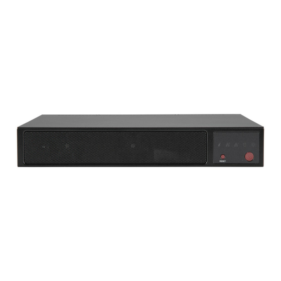
Chapter 1: Introduction 1.2 System Features The following views of the system display the main features. Refer to Appendix B for additional specifications. Front View Control Panel Figure 1-1. Front View NIC LEDs Power LED Information LED Reset Power Figure 1-2. Control Panel... -
Page 10: Control Panel
Chapter 1: Introduction Control Panel Control Panel Features Feature Description Information LED See table below for details. NIC2 LED Indicates network activity on LAN port 2 when flashing NIC1 LED Indicates network activity on LAN port 1 when flashing HDD LED Indicates activity on a hard drive when flashing. -
Page 11: Rear View
Chapter 1: Introduction Rear View Display Port HDMI Ports Line Out/Mic In LAN Ports USB Ports Power Adapter Figure 1-3. System: Rear View System Features: Rear Feature Description Power Adapter One DC power adapter Display Port One display port HDMI Ports Two HDMI 2.0 ports Four USB 3.2 ports, type A Two LAN ports... -
Page 12: Power Supply Indicators
Chapter 1: Introduction Power Supply Indicators Power Supply Indicators Power Supply Condition Green LED Amber LED No AC power to power supply Power supply critical events causing a shutdown/failure/OCP/OVP/fan failure/ OTP/UVP Power supply warning events when the power supply continues to operate, high Blinking at 1Hz temperature, over voltage, under voltage, etc. -
Page 13: Top View
Chapter 1: Introduction Top View Power Supply Module Processor 2 M.2 Slots 2 DIMM Slots 2 System Fans Figure 1-4. System: Top View System Features: Top Feature Description Power Supply Single 180W module M.2 slots Two NVMe M.2 hybrid slots DIMM slots Dual in-line memory module (DIMM) slots Processor... -
Page 14: System Architecture
Chapter 1: Introduction 1.3 System Architecture This section covers the locations of the system electrical components and block diagrams of the motherboard and the overall system. Main Components RSC-RR1U-E16 X12SCV-LVDS Figure 1-5. Main Component Locations... -
Page 15: Motherboard Layout
Chapter 1: Introduction 1.4 Motherboard Layout Below is a layout of the X12SCV-LVDS motherboard with jumper, connector, and LED locations shown. See the table on the following page for descriptions. For detailed descriptions, pinout information, and jumper settings, refer to Chapter 4 or the Motherboard Manual. LAN1 MIC_IN LAN2... -
Page 16: Quick Reference Table
Chapter 1: Introduction Quick Reference Table Jumper Description Default Setting (*) JBT1 CMOS Clear Open (Normal) C1, JI SMB to PCIe Slots Enable/Disable Pins 2-3 (Disabled) JLCDPWR1 LVDS Panel VCC Power 3.3V/5V Pins 1-2 (3.3V) JPAC1 Audio Enable Pins 1-2 (Enabled) JPL1 LAN1 Enable/Disable Pins 1-2 (Enabled) - Page 17 Chapter 1: Introduction Connector Description LINE_OUT HD Audio Line Out LVDS1 Low Voltage Differential Signaling (LVDS) Connector MIC_IN HD Audio Mic In MH1 - MH4 Mounting Holes SLOT7 CPU PCIe 3.0 x16 Slot USB0/1, 2/3 Front Accessible USB 2.0 Ports USB4/5, 6/7 Back Panel USB 3.2 Ports...
-
Page 18: Chipset Block Diagram
Chapter 1: Introduction Chipset Block Diagram SVID PCIe3.0_x16 IMVP8 PCIe x16 SLOT INTEL LGA1200 8.0GT/s Digital port 1 Display Port DDI 1 DDR4 (CHA) Digital port 2 DIMMA1 HDMI 1.4 DDI 2 2999MHz Digital port 3 HDMI 2.0 DDI 3 DDR4 (CHB) PS175 DIMMB1... -
Page 19: Chapter 2 Server Installation
Chapter 2: Server Installation Chapter 2 Server Installation 2.1 Overview This chapter provides advice and instructions for mounting your system in a server rack. If your system is not already fully integrated with processors, system memory, etc., refer to Chapter 3 for details on installing those specific components. -
Page 20: Rack Precautions
Chapter 2: Server Installation • This product is not suitable for use with visual display workplace devices according to §2 of the German Ordinance for Work with Visual Display Units. Rack Precautions • Ensure that the leveling jacks on the bottom of the rack are extended to the floor so that the full weight of the rack rests on them. -
Page 21: Airflow
Chapter 2: Server Installation Airflow Equipment should be mounted into a rack so that the amount of airflow required for safe operation is not compromised. Mechanical Loading Equipment should be mounted into a rack so that a hazardous condition does not arise due to uneven mechanical loading. -
Page 22: Installing Rack Mounting Brackets
Chapter 2: Server Installation 2.4 Installing Rack Mounting Brackets The chassis can be mounted in a rack using two rack brackets and a two-part power adapter shelf bracket (optional, MCP-290-30002-0B). 1. Attach the rack brackets using three screws through the holes in each bracket to secure the bracket to the chassis. -
Page 23: Chapter 3 Maintenance And Component Installation
Chapter 3: Maintenance and Component Installation Chapter 3 Maintenance and Component Installation This chapter provides instructions on installing and replacing main system components. To prevent compatibility issues, only use components that match the specifications and/or part numbers given. Installation or replacement of most components require that power first be removed from the system. -
Page 24: Accessing The System
Chapter 3: Maintenance and Component Installation 3.2 Accessing the System The CSE-E300 chassis features a removable top cover, which allows easy access to the inside of the chassis. Removing the Top Cover 1. Begin by removing power from the system as described in Section 3.1. 2. -
Page 25: Processor And Heatsink Installation
Thermal grease is pre-applied on a new heatsink. No additional thermal grease is needed. • Refer to the Supermicro website for updates on processor support. • All graphics in this manual are for illustration only. Your components may look different. - Page 26 Chapter 3: Maintenance and Component Installation 2. Gently lift the load lever to open the load plate. Remove the plastic protective cover. Do not touch the CPU socket contacts. 3. Locate the triangle on the CPU and CPU socket, which indicates the location of Pin 1. Holding the CPU by the edges with your thumb and index finger, align the triangle on the CPU with the triangle on the socket.
-
Page 27: Installing An Active Cpu Heatsink With Fan
Chapter 3: Maintenance and Component Installation 5. Close the load plate, then gently push down the load lever into its locked position. CPU properly installed Load lever locked into place Note: You can only install the CPU in one direction. Make sure it is properly inserted into the socket before closing the load plate. - Page 28 Chapter 3: Maintenance and Component Installation 6. Align the four heatsink fastener screws with the mounting holes on the motherboard. In a diagonal order (example: #1 and #2, then #3 and #4), screw the fasteners clockwise into the mounting holes. Lock Unlock 7.
-
Page 29: Removing The Heatsink
Chapter 3: Maintenance and Component Installation Removing the Heatsink Note: We do not recommend that the CPU or heatsink be removed. However, if you do need to remove the heatsink, please follow the instructions below to remove the heatsink and prevent damage done to the CPU or other components. 1. -
Page 30: Memory
32GB 32GB 32GB 32GB 64GB Check the Supermicro website for possible updates to memory support. General Guidelines for Optimizing Memory Performance • The blue slots must be populated first. DIMM slots must be populated in the following order: DIMMA1, DIMMB1. -
Page 31: Dimm Installation
Chapter 3: Maintenance and Component Installation DIMM Installation 1. Install the desired number of SODIMMs into the memory slots, starting with DIMMA1 and then DIMMB1. 2. Align the key on the bottom of the SODIMM module against the receptive point on the memory slot. -
Page 32: Motherboard Battery
Chapter 3: Maintenance and Component Installation 3.5 Motherboard Battery The motherboard uses non-volatile memory to retain system information when system power is removed. This memory is powered by a lithium battery residing on the motherboard. Replacing the Battery Begin by removing power from the system. 1. -
Page 33: Storage Drives
One is installed to a mounting tray inside the chassis and the other is installed with a bracket. Note: Enterprise level hard disk drives are recommended for use in Supermicro chassis and servers. For information on recommended HDDs, visit the Supermicro website product pages. - Page 34 Chapter 3: Maintenance and Component Installation 3. Place the drive into the tray and secure it to the tray with the screws provided with the drive. 4. Return the drive tray assembly into the chassis, aligning the tabs of the tray with the slots in the chassis.
-
Page 35: Solid State Storage
Chapter 3: Maintenance and Component Installation 3.7 Solid State Storage This motherboard supports two internally mounted solid state storage cards on M.2 slots supporting PCIe 3.0 x4, for NVMe storage of 2242/2280 length. Note: The image below may not reflect the same layout as your system. M.2 is formerly known as Next Generation Form Factor (NGFF). - Page 36 Chapter 3: Maintenance and Component Installation M.2 2280 M.2 2230 Figure 3-5. Installing a PCIe Card and an M.2 Card...
-
Page 37: Riser Card
Chapter 3: Maintenance and Component Installation 3.8 Riser Card The system can support one PCIe x16 expansion card by means of an optional riser card. The riser card is inserted in the expansion slot on the motherboard. Installation of the riser card and riser card bracket is pictured below. -
Page 38: System Cooling
Chapter 3: Maintenance and Component Installation 3.9 System Cooling Two replaceable 4cm fans provide the cooling for the system. Make sure the chassis top cover makes a good seal so the cooling air circulates properly through the chassis. Figure 3-7. Fan Positions Installing Fans The E300-12C chassis includes two pre-installed fans. - Page 39 Chapter 3: Maintenance and Component Installation 6. Secure the fan to the chassis wall using the screws previously set aside. 7. Reconnect the fan wiring to motherboard. 8. Reinstall the chassis top cover, reconnect the AC power cord, and power up the system. Figure 3-8.
-
Page 40: Bmc
Chapter 3: Maintenance and Component Installation 3.10 BMC The BMC can be reset using the button on the front control panel or on the chassis rear. • Reset—Press and hold the button. After six seconds, the LED blinks at 2Hz. The BMC resets and the reset duration is ~250ms. -
Page 41: Cable Routing Diagram
Chapter 3: Maintenance and Component Installation 3.11 Cable Routing Diagram Refer to the diagram below for a representation of how the main cables are routed throughout the system. When disconnecting cables to add or replace components, refer to this diagram when adding or replacing components so you can reroute them in the same manner. -
Page 42: Chapter 4 Motherboard Connections
Chapter 4: Motherboard Connections Chapter 4 Motherboard Connections This section describes the connections on the motherboard and provides pinout definitions. Note that depending on how the system is configured, not all connections are required. The LEDs on the motherboard are also described here. A motherboard layout indicating component locations may be found in Chapter 1. - Page 43 Chapter 4: Motherboard Connections BAR CODE JLCDPWR1 MAC CODE USB2/3 I-SATA1 DIMMA1 JBT1 I-SATA2 8-Pin Power Connector JMD1_SRW1 DIMMB1 JPV1 is an 8-pin 12V DC power input for CPU or alternative single power source for a special enclosure when the 24-pin ATX power is not in use. Refer to the table below for pin definitions. JMD2 FAN1 LED1...
-
Page 44: Headers And Connectors
JMD2_SRW1 Chapter 4: Motherboard Connections 4.2 Headers and Connectors Fan Headers There are three 4-pin fan headers on the motherboard. Although pins 1-3 of the fan headers are backward compatible with the traditional 3-pin fans, we recommend you use 4-pin fans to take advantage of the fan speed control via Pulse Width Modulation through the thermal management. - Page 45 Port 80 connection. Use this header to enhance system performance and data security. Refer to the table below for pin definitions. Please go to the following link for more information on the TPM: http://www.supermicro.com/manuals/other/TPM.pdf. Trusted Platform Module Header Pin Definitions...
- Page 46 Chapter 4: Motherboard Connections M.2 Slot The motherboard has two M.2 slots (JMD1 and JMD2). M.2 was formerly known as Next Generation Form Factor (NGFF) and serves to replace mini PCIe. M.2 allows for a variety of card sizes, increased functionality, and spatial efficiency. JMD1 supports an E-Key CNVi/PCIe 3.0 x1 device in the 2230 form factor, whereas JMD2 supports an M-Key SATA/ PCIe 3.0 x4 device in the 2242 and 2280 form factors.
- Page 47 Chapter 4: Motherboard Connections COM Header The motherboard has one COM header that provides two serial connections (COM1/2) and supports RS-232 function, utilizing Supermicro PN: CBL-CDAT-0604 or CBL-CUSB-0984 (not included). COM Header (COM1/2) Pin Definitions Pin# Definition Pin# Definition DCDA...
-
Page 48: Control Panel
JF1 contains header pins for various buttons and indicators that are normally located on a control panel at the front of the chassis. These connectors are designed specifically for use with Supermicro chassis. See the figure below for the descriptions of the front control panel buttons and LED indicators. - Page 49 Chapter 4: Motherboard Connections Overheat (OH)/Fan Fail Connect an LED cable to pins 7 and 8 of the Front Control Panel to use the Overheat/Fan Fail LED connections. The LED on pin 8 provides warnings of overheating or fan failure. Refer to the tables below for pin definitions.
- Page 50 Chapter 4: Motherboard Connections NMI Button The non-maskable interrupt (NMI) button header is located on pins 19 and 20 of JF1. Refer to the table below for pin definitions. NMI Button Pin Definitions (JF1) Pins Definition Control Ground...
-
Page 51: Input/Output Ports
Chapter 4: Motherboard Connections 4.3 Input/Output Ports Rear I/O Ports See the figure below for the locations and descriptions of the I/O ports on the rear of the motherboard. Rear I/O Ports Description Description Description DisplayPort USB6 (3.2) LAN2 HDMI 2.0 USB5 (3.2) LINE_OUT HDMI 1.4... - Page 52 Chapter 4: Motherboard Connections LAN Ports Two Gigabit Ethernet ports (LAN1/2) are located on the I/O back panel. All of these ports accept RJ45 cables. Refer to the table below for pin definitions. LAN Port Pin Definition Pin# Definition Pin# Definition TX_D1+ TX_D3+...
-
Page 53: Jumpers
Chapter 4: Motherboard Connections 4.4 Jumpers Explanation of Jumpers To modify the operation of the motherboard, jumpers are used to choose between optional settings. Jumpers create shorts between two pins to change the function associated with it. Pin 1 is identified with a square solder pad on the printed circuit board. See the motherboard layout page for jumper locations. - Page 54 Chapter 4: Motherboard Connections Watch Dog Timer Watchdog (JWD1) is a system monitor that can reboot the system when a software application hangs. Close pins 1-2 to reset the system if an application hangs. Close pins 2-3 to generate a non-maskable interrupt (NMI) signal for the application that hangs. Refer to the table below for jumper settings.
- Page 55 Chapter 4: Motherboard Connections LVDS Power Voltage Use this jumper to select the power voltage for the LVDS panel. Make sure that the specifications of the cable are compatible with the panel to prevent damage. LVDS Voltage Selection Jumper Settings Jumper Setting Definition Pins 1-2...
-
Page 56: Led Indicators
Chapter 4: Motherboard Connections 4.5 LED Indicators LAN LEDs Two LAN ports (LAN 1/2) are located on the I/O back panel of the motherboard. Each Ethernet LAN port has two LEDs. The green LED indicates activity, while the other Link LED may be green, amber, or off to indicate the speed of the connection. -
Page 57: Storage Ports
There are two SATA 3.0 ports supported by the Intel PCH W480E chipset. SATA ports provide serial-link signal connections, which are faster than the connections of Parallel ATA. Note: For more information on the SATA HostRAID configuration, please refer to the Intel SATA HostRAID user's guide posted on our website at https://www.supermicro.com/support/manuals/. -
Page 58: Chapter 5 Software
USB/SATA DVD drive, or a USB flash drive, or the IPMI KVM console. 2. Retrieve the proper RST/RSTe driver. Go to the Supermicro web page for your motherboard and click on "Download the Latest Drivers and Utilities", select the proper driver, and copy it to a USB flash drive. - Page 59 Chapter 5: Software 4. During Windows Setup, continue to the dialog where you select the drives on which to install Windows. If the disk you want to use is not listed, click on the “Load driver” link in the bottom left corner. Figure 5-2.
-
Page 60: Driver Installation
The Supermicro website contains drivers and utilities for your system at https://www. supermicro.com/wdl/driver. Some of these must be installed, such as the chipset driver. After accessing the website, go into the CDR_Images (in the parent directory of the above link) and locate the ISO file for your motherboard. Download this file to a USB flash drive or a DVD. -
Page 61: Superdoctor ® 5
5.3 SuperDoctor ® The Supermicro SuperDoctor 5 is a hardware monitoring program that functions in a command-line or web-based interface in Windows and Linux operating systems. The program monitors system health information such as CPU temperature, system voltages, system power consumption, and fan speed, and provides alerts via email or Simple Network Management Protocol (SNMP). -
Page 62: Chapter 6 Optional Components
Chapter 6: Optional Components Chapter 6 Optional Components This chapter describes optional system components and installation procedures. 6.1 Optional Parts List Optional Parts List Description Part Number Quantity Rackmount Kit MCP-290-30002-0B SATA Cable CBL-0473L 6.2 Rackmount Kit The server can be mounted in a rack using an optional rackmount kit (MCP-290-30002-0B). The kit consists of two rack brackets and a two-part power adapter shelf bracket. -
Page 63: Chapter 7 Troubleshooting And Support
Chapter 7 Troubleshooting and Support 7.1 Information Resources Website A great deal of information is available on the Supermicro website, supermicro.com. Menu Icon Figure 7-1. Supermicro Website • Specifications for servers and other hardware are available by clicking the menu icon, then selecting the Products option. -
Page 64: Direct Links For General Support And Information
SuperDoctor5 Large Deployment Guide For validated memory, use our Product Resources page Product Matrices page for links to tables summarizing specs for systems, motherboards, power supplies, riser cards, add-on cards, etc. Security Center for recent security notices Supermicro Phone and Addresses... -
Page 65: Troubleshooting Procedures
Chapter 7: Troubleshooting and Support 7.2 Troubleshooting Procedures Use the following procedures to troubleshoot your system. If you have followed all of the procedures below and still need assistance, refer to the Technical Support Procedures Returning Merchandise for Service section(s) in this chapter. Power down the system before changing any non-hot-swap hardware components. -
Page 66: System Boot Failure
Chapter 7: Troubleshooting and Support System Boot Failure If the system does not display POST (Power-On-Self-Test) or does not respond after the power is turned on, check the following: 1. Check for any error beep from the motherboard speaker. • If there is no error beep, try to turn on the system without DIMM modules installed. -
Page 67: Losing The System's Setup Configuration
Chapter 7: Troubleshooting and Support Losing the System's Setup Configuration 1. Make sure that you are using a high-quality power supply. A poor-quality power supply may cause the system to lose the CMOS setup information. Refer to Chapter 2 for details on recommended power supplies. - Page 68 Chapter 7: Troubleshooting and Support and a memory module installed) to identify the trouble areas. Refer to the steps listed in Section A above for proper troubleshooting procedures. 4. Identifying bad components by isolating them: If necessary, remove a component in question from the chassis, and test it in isolation to make sure that it works properly.
-
Page 69: Uefi Bios Recovery
Warning: Do not upgrade the BIOS unless your system has a BIOS-related issue. Flashing the wrong BIOS can cause irreparable damage to the system. In no event shall Supermicro be liable for direct, indirect, special, incidental, or consequential damages arising from a BIOS update. - Page 70 USB device or a writable CD/DVD. Note 1: If you cannot locate the "Super.ROM" file in your drive disk, visit our website at www.supermicro.com to download the BIOS package. Extract the BIOS binary image into a USB flash device and rename it "Super.ROM" for the BIOS recovery use.
- Page 71 Chapter 7: Troubleshooting and Support 3. After locating the healthy BIOS binary image, the system will enter the BIOS Recovery menu as shown below. Note: At this point, you may decide if you want to start the BIOS recovery. If you decide to proceed with BIOS recovery, follow the procedures below.
- Page 72 Chapter 7: Troubleshooting and Support 5. After the BIOS recovery process is complete, press any key to reboot the system. 6. Using a different system, extract the BIOS package into a USB flash drive. 7. Press <Del> continuously during system boot to enter the BIOS Setup utility. From the top of the tool bar, select Boot to enter the submenu.
- Page 73 Chapter 7: Troubleshooting and Support 8. When the UEFI Shell prompt appears, type fs# to change the device directory path. Go to the directory that contains the BIOS package you extracted earlier from Step 6. Enter flash.nsh BIOSname.### at the prompt to start the BIOS update process. Note: Do not interrupt this process until the BIOS flashing is complete.
-
Page 74: Cmos Clear
Chapter 7: Troubleshooting and Support 7.4 CMOS Clear JBT1 is used to clear CMOS, which will also clear any passwords. Instead of pins, this jumper consists of contact pads to prevent accidentally clearing the contents of CMOS. To Clear CMOS 1. -
Page 75: Where To Get Replacement Components
7.5 Where to Get Replacement Components If you need replacement parts for your system, to ensure the highest level of professional service and technical support, purchase exclusively from our Supermicro Authorized Distributors/System Integrators/Resellers. A list can be found at: http://www.supermicro.com. -
Page 76: Vendor Support Filing System
For issues related to Red Hat Enterprise Linux, since it is a subscription based OS, contact your account representative. 7.7 Feedback Supermicro values your feedback as we strive to improve our customer experience in all facets of our business. Please email us at techwriterteam@supermicro.com to provide feedback on our manuals. -
Page 77: Contacting Supermicro
Chapter 7: Troubleshooting and Support 7.8 Contacting Supermicro Headquarters Address: Super Micro Computer, Inc. 980 Rock Ave. San Jose, CA 95131 U.S.A. Tel: +1 (408) 503-8000 Fax: +1 (408) 503-8008 Email: marketing@supermicro.com (General Information) support@supermicro.com (Technical Support) Website: www.supermicro.com Europe Address: Super Micro Computer B.V. -
Page 78: Appendix A Standardized Warning Statements For Ac Systems
Supermicro's Technical Support department for assistance. Only certified technicians should attempt to install or configure components. Read this appendix in its entirety before installing or configuring components in the Supermicro chassis. These warnings may also be found on our website at http://www.supermicro.com/about/... - Page 79 Appendix A: Warning Statements Warnung WICHTIGE SICHERHEITSHINWEISE Dieses Warnsymbol bedeutet Gefahr. Sie befinden sich in einer Situation, die zu Verletzungen führen kann. Machen Sie sich vor der Arbeit mit Geräten mit den Gefahren elektrischer Schaltungen und den üblichen Verfahren zur Vorbeugung vor Unfällen vertraut. Suchen Sie mit der am Ende jeder Warnung angegebenen Anweisungsnummer nach der jeweiligen Übersetzung in den übersetzten Sicherheitshinweisen, die zusammen mit diesem Gerät ausgeliefert wurden.
- Page 80 Appendix A: Warning Statements . ٌ ا ك ً ف حالة و ٌ يك أى تتسبب ف اصابة جسذ ة ٌ هذا الزهز ع ٌ خطز !تحذ ز قبل أى تعول عىل أي هعذات،يك عىل علن بالوخاطز ال ا ٌجوة عي الذوائز ٍ...
- Page 81 Appendix A: Warning Statements Warnung Vor dem Anschließen des Systems an die Stromquelle die Installationsanweisungen lesen. ¡Advertencia! Lea las instrucciones de instalación antes de conectar el sistema a la red de alimentación. Attention Avant de brancher le système sur la source d'alimentation, consulter les directives d'installation. .יש...
- Page 82 Appendix A: Warning Statements Warnung Dieses Produkt ist darauf angewiesen, dass im Gebäude ein Kurzschluss- bzw. Überstromschutz installiert ist. Stellen Sie sicher, dass der Nennwert der Schutzvorrichtung nicht mehr als: 250 V, 20 A beträgt. ¡Advertencia! Este equipo utiliza el sistema de protección contra cortocircuitos (o sobrecorrientes) del edificio.
- Page 83 Appendix A: Warning Statements Power Disconnection Warning Warning! The system must be disconnected from all sources of power and the power cord removed from the power supply module(s) before accessing the chassis interior to install or remove system components. 電源切断の警告 システムコンポーネントの取り付けまたは取り外しのために、...
- Page 84 Appendix A: Warning Statements אזהרה מפני ניתוק חשמלי !אזהרה יש לנתק את המערכת מכל מקורות החשמל ויש להסיר את כבל החשמלי מהספק .לפני גישה לחלק הפנימי של המארז לצורך התקנת או הסרת רכיבים يجب فصم اننظاو من جميع مصادر انطاقت وإ ز انت سهك انكهرباء من وحدة امداد انطاقت...
- Page 85 Appendix A: Warning Statements ¡Advertencia! Solamente el personal calificado debe instalar, reemplazar o utilizar este equipo. Attention Il est vivement recommandé de confier l'installation, le remplacement et la maintenance de ces équipements à des personnels qualifiés et expérimentés. !אזהרה .צוות מוסמך בלבד רשאי להתקין, להחליף את הציוד או לתת שירות עבור הציוד واملدربيه...
- Page 86 Appendix A: Warning Statements Warnung Diese Einheit ist zur Installation in Bereichen mit beschränktem Zutritt vorgesehen. Der Zutritt zu derartigen Bereichen ist nur mit einem Spezialwerkzeug, Schloss und Schlüssel oder einer sonstigen Sicherheitsvorkehrung möglich. ¡Advertencia! Esta unidad ha sido diseñada para instalación en áreas de acceso restringido. Sólo puede obtenerse acceso a una de estas áreas mediante la utilización de una herramienta especial, cerradura con llave u otro medio de seguridad.
- Page 87 Appendix A: Warning Statements Battery Handling Warning! There is the danger of explosion if the battery is replaced incorrectly. Replace the battery only with the same or equivalent type recommended by the manufacturer. Dispose of used batteries according to the manufacturer's instructions 電池の取り扱い...
- Page 88 Appendix A: Warning Statements هناك خطر من انفجار يف حالة اسحبذال البطارية بطريقة غري صحيحة فعليل اسحبذال البطارية فقط بنفس النىع أو ما يعادلها مام أوصث به الرشمة املصنعة جخلص من البطاريات املسحعملة وفقا لحعليامت الرشمة الصانعة 경고! 배터리가 올바르게 교체되지 않으면 폭발의 위험이 있습니다. 기존 배터리와 동일하거나 제 조사에서...
- Page 89 Appendix A: Warning Statements ¡Advertencia! Puede que esta unidad tenga más de una conexión para fuentes de alimentación. Para cortar por completo el suministro de energía, deben desconectarse todas las conexiones. Attention Cette unité peut avoir plus d'une connexion d'alimentation. Pour supprimer toute tension et tout courant électrique de l'unité, toutes les connexions d'alimentation doivent être débranchées.
- Page 90 Appendix A: Warning Statements Backplane Voltage Warning! Hazardous voltage or energy is present on the backplane when the system is operating. Use caution when servicing. バックプレーンの電圧 システムの稼働中は危険な電圧または電力が、 バックプレーン上にかかっています。 修理する際には注意く ださい。 警告 当系统正在进行时,背板上有很危险的电压或能量,进行维修时务必小心。 警告 當系統正在進行時,背板上有危險的電壓或能量,進行維修時務必小心。 Warnung Wenn das System in Betrieb ist, treten auf der Rückwandplatine gefährliche Spannungen oder Energien auf.
- Page 91 Appendix A: Warning Statements هناك خطز مه التيار الكهزبايئ أوالطاقة املىجىدة عىل اللىحة عندما يكىن النظام يعمل كه حذ ر ا عند خدمة هذا الجهاس 경고! 시스템이 동작 중일 때 후면판 (Backplane)에는 위험한 전압이나 에너지가 발생 합니다. 서비스 작업 시 주의하십시오. Waarschuwing Een gevaarlijke spanning of energie is aanwezig op de backplane wanneer het systeem in gebruik is.
- Page 92 Appendix A: Warning Statements תיאום חוקי החשמל הארצי !אזהרה .התקנת הציוד חייבת להיות תואמת לחוקי החשמל המקומיים והארציים تركيب املعدات الكهربائية يجب أن ميتثل للقىاويه املحلية والىطىية املتعلقة بالكهرباء 경고! 현 지역 및 국가의 전기 규정에 따라 장비를 설치해야 합니다. Waarschuwing Bij installatie van de apparatuur moet worden voldaan aan de lokale en nationale elektriciteitsvoorschriften.
- Page 93 Appendix A: Warning Statements Attention La mise au rebut ou le recyclage de ce produit sont généralement soumis à des lois et/ou directives de respect de l'environnement. Renseignez-vous auprès de l'organisme compétent. סילוק המוצר !אזהרה .סילוק סופי של מוצר זה חייב להיות בהתאם להנחיות וחוקי המדינה التخلص...
- Page 94 Appendix A: Warning Statements Warnung Gefährlich Bewegende Teile. Von den bewegenden Lüfterblätter fern halten. Die Lüfter drehen sich u. U. noch, wenn die Lüfterbaugruppe aus dem Chassis genommen wird. Halten Sie Finger, Schraubendreher und andere Gegenstände von den Öffnungen des Lüftergehäuses entfernt.
- Page 95 Verbindungskabeln, Stromkabeln und/oder Adapater, die Ihre örtlichen Sicherheitsstandards einhalten. Der Gebrauch von anderen Kabeln und Adapter können Fehlfunktionen oder Feuer verursachen. Die Richtlinien untersagen das Nutzen von UL oder CAS zertifizierten Kabeln (mit UL/CSA gekennzeichnet), an Geräten oder Produkten die nicht mit Supermicro gekennzeichnet sind.
- Page 96 .قيرح وأ لطع يف ببستي دق ىرخأ تالوحمو تالباك يأ مادختسا .ميلسلا سباقلاو لصوملا مجح لبق نم ةدمتعملا تالباكلا مادختسا تادعملاو ةيئابرهكلا ةزهجألل ةمالسلا نوناق رظحيUL وأCSA ( ةمالع لمحت يتلاوUL/CSA) لبق نم ةددحملاو ةينعملا تاجتنملا ريغ ىرخأ تادعم يأ عمSupermicro.
- Page 97 사항을 준수하여 제공되거나 지정된 연결 혹은 구매 케이블, 전원 케이블 및 AC 어댑터를 사용하십시오. 다른 케이블이나 어댑터를 사용하면 오작동이나 화재가 발생할 수 있습니다. 전기 용품 안전법은 UL 또는 CSA 인증 케이블 (코드에 UL / CSA가 표시된 케이블)을 Supermicro 가 지정한 제품 이외의 전기 장치에 사용하는 것을 금지합니다. Stroomkabel en AC-Adapter...
-
Page 98: Appendix B System Specifications
Appendix B: System Specifications Appendix B System Specifications Processors Intel W-1200 series, 10th Generation Core i9/i7/i5/i3 series, Pentium, Celeron, and Xeon processors with a thermal design power (TDP) of up to 65W in an LGA1200 socket Note: Refer to the motherboard specifications pages on our website for updates to supported processors. Chipset Intel PCH W480E BIOS... - Page 99 Appendix B: System Specifications Regulatory Compliance FCC, ICES, CE, VCCI, RCM, UKCA, NRTL, CB Applied Directives, Standards EMC/EMI: 2014/30/EU (EMC Directive) Electromagnetic Compatibility Regulations 2016 FCC Part 15 Subpart B ICES-003 VCCI-CISPR 32 AS/NZS CISPR 32 EN/BS 55032 EN/BS 55035 EN/BS 61000-3-2 EN/BS 61000-3-3 EN/BS 61000-4-2...
Need help?
Do you have a question about the SuperServer E300-12C and is the answer not in the manual?
Questions and answers