Table of Contents
Advertisement
Quick Links
Advertisement
Table of Contents

Related Manuals for Supermicro SuperServer E403-9P-FN2T


Summary of Contents for Supermicro SuperServer E403-9P-FN2T
- Page 1 SuperServer ® E403-9P-FN2T USER’S MANUAL Revision 1.0a...
- Page 2 State of California, USA. The State of California, County of Santa Clara shall be the exclusive venue for the resolution of any such disputes. Supermicro's total liability for all claims will not exceed the price paid for the hardware product.
- Page 3 If you have any questions, please contact our support team at: support@supermicro.com This manual may be periodically updated without notice. Please check the Supermicro website for possible updates to the manual revision level. Secure Data Deletion A secure data deletion tool designed to fully erase all data from storage devices can be found on our website: https://www.supermicro.com/about/policies/disclaimer.cfm?url=/wdl/utility/...
-
Page 4: Table Of Contents
SuperServer E403-9P-FN2T User's Manual Contents Chapter 1 Introduction 1.1 Overview ..........................8 1.2 Unpacking the System ......................8 1.3 System Features ........................9 1.4 Chassis Features .......................10 Control Panel ........................10 Chassis Front ........................11 Chassis Rear ........................12 1.5 Motherboard Layout ......................13 Quick Reference .......................14 System Block Diagram ......................16... - Page 5 Contents Memory Population Sequence ..................31 Installing Memory ......................33 Motherboard Battery ......................34 2.4 Chassis Components ......................35 Installing the Storage Drives ....................35 System Cooling .........................37 Installing the Air Shrouds ....................38 Checking the Server Air Flow ..................39 Overheating ........................39 Expansion Cards .......................39 M.2 Solid State Drives ....................42 Wall Mount Procedure .......................44 Power Supply ........................47 Chapter 3 Motherboard Connections...
- Page 6 SuperServer E403-9P-FN2T User's Manual 5.7 Boot ..........................108 5.8 Save & Exit ........................111 Appendix A BIOS Error Codes Appendix B Standardized Warning Statements for AC Systems Appendix C System Specifications BSMI Chinese Safety Warnings Appendix D UEFI BIOS Recovery Appendix E IPMI Crash Dump...
- Page 7 SuperServer E403-9P-FN2T User's Manual Contacting Supermicro Contacting Supermicro Headquarters Address: Super Micro Computer, Inc. 980 Rock Ave. San Jose, CA 95131 U.S.A. Tel: +1 (408) 503-8000 Fax: +1 (408) 503-8008 Email: marketing@supermicro.com (General Information) support@supermicro.com (Technical Support) Website: www.supermicro.com Europe Address: Super Micro Computer B.V.
-
Page 8: Overview
SuperServer E403-9P-FN2T User's Manual Chapter 1 Introduction 1.1 Overview This chapter provides a brief outline of the functions and features of the E403-9P-FN2T server. It is based on the X11SPW-TF motherboard and the E403iF chassis. In addition to the motherboard and chassis, several important parts that are included with the system are listed below. -
Page 9: System Features
Single Intel Xeon 81xx/61xx/51xx/41xx/31xx or Xeon 82xx/62xx/52xx/42xx/32xx processors (Intel Scalable Processors) in Socket P0 (LGA3647) For the latest CPU/memory updates, refer to our website at http://www.supermicro.com/products/motherboard/Xeon/C620/X11SPW-TF.cfm. Memory Six slots for up to 1.5TB DDR4 3DS ECC RDIMM or LRDIMM memory with speeds of up to 2933MHz... -
Page 10: Chassis Features
SuperServer E403-9P-FN2T User's Manual 1.4 Chassis Features Control Panel Power switches and status LEDs are located on the control panel on the front of the chassis. Figure 1-1. Control Panel Control Panel Features Item Features Description The main power switch applies or removes primary power from the power supply to Power button the server but maintains standby power. -
Page 11: Chassis Front
Chapter 1: Introduction Chassis Front The illustration below shows the features on the front of the chassis. Figure 1-2. Front View Front Chassis Features Item Features Description Power Input Main power input USB ports External USB 3.0, Type A ports PCI Slots Three PCIe expansion slots Ground... -
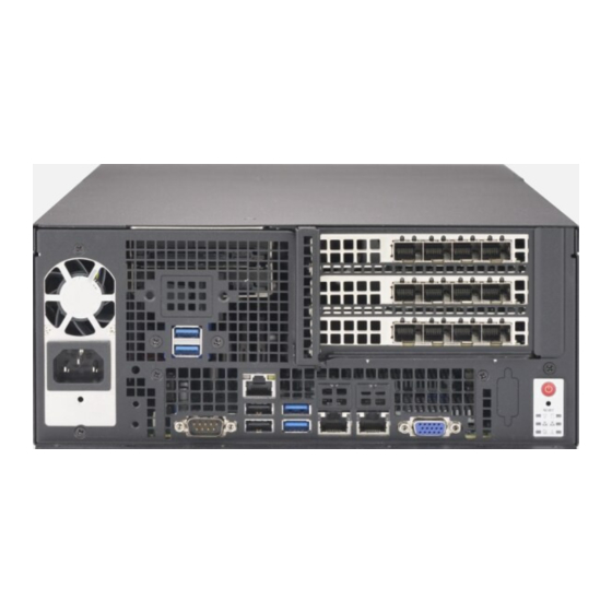
Page 12: Chassis Rear
SuperServer E403-9P-FN2T User's Manual Figure 1-3. Rear I/O Ports Description Description COM Port 1 USB7 (3.0) Dedicated BMC LAN LAN1 USB1 (2.0) LAN2 USB0 (2.0) VGA Port USB8 (3.0) UID Switch Chassis Rear The illustration below shows three system fans included on the rear of the chassis. -
Page 13: Motherboard Layout
Chapter 1: Introduction 1.5 Motherboard Layout Below is a layout of the X11SPW-TF with jumper, connector and LED locations shown. See the table on the following page for descriptions. For detailed descriptions, pinout information and jumper settings, refer to Chapter 4. BMC Password Label JWD1 USB7/8 (3.0) -
Page 14: Quick Reference
M.2 PCIe 3.0 x4 or SATA 3.0 Slot MH10, MH11 M.2 Mounting Holes Internal Speaker/Buzzer S-SATA0~1 SATA 3.0 Ports with SATA DOM Power SXB1A, SXB1B, SXB1C Supermicro Proprietary WIO Left Add-on Card Slots SXB2 Supermicro Proprietary WIO Right Add-on Card Slot... - Page 15 Chapter 1: Introduction Connector Description USB0/1 Back Panel Universal Serial Bus (USB) 2.0 Ports USB2/3, USB4/5 Front Accessible USB 2.0 Headers USB6 USB 2.0 Header (Not customized for the front panel) USB7/8 Back Panel USB 3.0 Ports USB9 USB 3.0 Type-A Header USB10/11 Front Accessible USB 3.0 Header VGA Port...
-
Page 16: System Block Diagram
SuperServer E403-9P-FN2T User's Manual System Block Diagram VCCP0 12v VR13 5+1 PHASE #F-1 #C-1 205W #E-1 #B-1 #D-1 #A-1 VCCP0 SNB CORE PECI:30 DDR-IV SOCKET ID:0 DMI3 PCI-E X8 G3 DMI3 PCI-E X16 G3 PCI-E X16 G3 PCI-E X4 G3... -
Page 17: Server Installation And Setup
Chapter 1: Introduction 1.6 Server Installation and Setup The server is shipped with the motherboard installed in the chassis. Several steps are necessary to begin using your server. You must add memory, mount the hard disk drive, and mount the system in place. Unpacking the System Inspect the box in which the system was shipped and note if it was damaged. -
Page 18: Where To Get Replacement Components
(http://www.supermicro.com/ support/rma/). Whenever possible, repack the chassis in the original Supermicro carton, using the original packaging material. If these are no longer available, be sure to pack the chassis securely, using packaging material to surround the chassis so that it does not shift within the carton and become damaged during shipping. -
Page 19: Chapter 2 Maintenance And Component Installation
Chapter 2: Maintenance and Component Installation Chapter 2 Maintenance and Component Installation This chapter provides instructions on installing and replacing main system components. To prevent compatibility issues, only use components that match the specifications and/or part numbers given. Installation or replacement of most components require that power first be removed from the system. -
Page 20: Accessing The System
SuperServer E403-9P-FN2T User's Manual 2.2 Accessing the System The E403 chassis has a removable top cover to access internal components. Removing the Top Cover 1. Remove the three screws and rotate the rear portion of the cover up. Remove Screw... - Page 21 Chapter 2: Maintenance and Component Installation 2. Remove the final screw, then slide the cover toward the rear and lift. Remove Screw Figure 2-2. Removing the Chassis Cover Caution: Except for short periods of time, do not operate the server without the cover in place. The chassis cover must be in place to allow for proper airflow and to prevent overheating.
-
Page 22: Enabling The Top Cover Lock Function
SuperServer E403-9P-FN2T User's Manual Enabling the Top Cover Lock Function The chassis includes a lock plate that allows the top cover to be locked. 1. Pull the lock plate into a vertical position. 2. Close the fan cover. Make sure the lock plate fits through the slot on the cover. - Page 23 Chapter 2: Maintenance and Component Installation Figure 2-4. Top Cover Lock Tab...
-
Page 24: Motherboard Components
Thermal grease is pre-applied on a new heatsink. No additional thermal grease is needed. • Refer to the Supermicro website for updates on processor support. • All graphics in this manual are for illustration only. Your components may look different. -
Page 25: Overview Of The Processor Heatsink Module
Chapter 2: Maintenance and Component Installation Overview of the Processor Heatsink Module The Processor Heatsink Module (PHM) contains a heatsink, a processor carrier, and the processor. Heatsink with Thermal Grease Processor Carrier Processor Processor Heatsink Module Bottom View... -
Page 26: Creating The Processor Carrier Assembly
SuperServer E403-9P-FN2T User's Manual Creating the Processor Carrier Assembly To install a processor into the processor carrier, follow the steps below: 1. Hold the processor with the LGA lands (gold contacts) facing up. Locate the small, gold triangle in the corner of the processor and the corresponding hollowed triangle on the processor carrier. -
Page 27: Assembling The Processor Heatsink Module
Chapter 2: Maintenance and Component Installation Assembling the Processor Heatsink Module After creating the processor carrier assembly, mount it onto the heatsink to create the processor heatsink module (PHM): 1. Note the label on top of the heatsink, which marks the heatsink mounting holes as 1, 2, 3, and 4. -
Page 28: Preparing The Cpu Socket For Installation
SuperServer E403-9P-FN2T User's Manual Preparing the CPU Socket for Installation This motherboard comes with a plastic protective cover on the CPU socket. Remove it carefully to install the Processor Heatsink Module (PHM). CPU Socket with Plastic Protective Cover Remove the plastic protective cover from the CPU socket. -
Page 29: Installing The Processor Heatsink Module
Chapter 2: Maintenance and Component Installation Installing the Processor Heatsink Module After assembling the Processor Heatsink Module (PHM), install it onto the CPU socket: 1. Align hole 1 of the heatsink with the printed triangle on the CPU socket. See the left image below. -
Page 30: Memory
*4Gb DRAM density is only supported on speeds up to 2666 MT/s **Only the 82xx and 62xx series support 2933 MT/s; for other processors, memory speed as supported by the CPU. Check the Supermicro website for possible updates to memory support. -
Page 31: Memory Population Guidelines
Then, if using two DIMMs per channel, install the second DIMM in the black slot. The following memory population sequence table was created based on guidelines provided by Intel to support Supermicro motherboards. The diagram is for illustrative purposes; your motherboard may look different. - Page 32 SuperServer E403-9P-FN2T User's Manual Memory Population, 6 DIMM Slots DIMMs Memory Population Sequence DIMMA1 DIMMA1 / DIMMD1 DIMMC1 / DIMMB1 / DIMMA1 DIMMB1 / DIMMA1 / DIMMD1 / DIMME1 DIMMC1 / DIMMB1 / DIMMA1 / DIMMD1 / DIMME1 DIMMC1 / DIMMB1 / DIMMA1 / DIMMD1 / DIMME1 / DIMMF1 *Unbalanced, not recommended.
-
Page 33: Installing Memory
Chapter 2: Maintenance and Component Installation Installing Memory ESD Precautions Electrostatic Discharge (ESD) can damage electronic com ponents including memory modules. To avoid damaging DIMM modules, it is important to handle them carefully. The following measures are generally sufficient. • Use a grounded wrist strap designed to prevent static discharge. -
Page 34: Motherboard Battery
SuperServer E403-9P-FN2T User's Manual Motherboard Battery The motherboard uses non-volatile memory to retain system information when system power is removed. This memory is powered by a lithium battery residing on the motherboard. Replacing the Battery Begin by removing power from the system as described in section 3.1. -
Page 35: Chassis Components
The E403-9P-FN2T can accommodate up to four fixed 2.5" SATA storage drives that are installed to a drive cage, and then inserted into the chassis. Note: Enterprise level hard disk drives are recommended for use in Supermicro chassis and servers. For information on recommended HDDs, visit the Supermicro website at https://www. - Page 36 SuperServer E403-9P-FN2T User's Manual 3. Pull the drive cage upwards using the provided plastic handles. Figure 2-8. Installing the Drives 4. Place the drives inside the cage, stacked up to two units on each end, then secure them inside the drive bays with the included screws, as shown above.
-
Page 37: System Cooling
Chapter 2: Maintenance and Component Installation System Cooling The system includes three replaceable 8-cm x 3.8-cm fans and shrouds to direct air flow. Caution: Since the system continues to draw a small amount of power in standby mode (and fans are off), there is a potential for overheating if the system is idle for a long time. In this situation, there is no warning from the overheat/fan fail LED. -
Page 38: Installing The Air Shrouds
SuperServer E403-9P-FN2T User's Manual Installing the Air Shrouds Air shroud concentrates airflow to maximize fan efficiency. It does not require screws to install. Installing the Air Shrouds 1. If you are installing full height PCIe expansion cards, you must cut one, two, or three sections of the shroud to create space for the cards. -
Page 39: Checking The Server Air Flow
Chapter 2: Maintenance and Component Installation 3. Place the air shroud. The small rectangular portion covers the DIMMA1/DIMMB1/ DIMMC1 memory modules. 4. Replace the chassis cross bracket. Checking the Server Air Flow • Make sure there are no objects to obstruct airflow in and out of the server. •... - Page 40 SuperServer E403-9P-FN2T User's Manual Note: When you add or change an expansion card, and if you load the BIOS default, clear CMOS, or update your BIOS, you must configure: UEFI BIOS > Advanced tab > Chipset Configuration > North Bridge > IIO Configuration >...
- Page 41 Chapter 2: Maintenance and Component Installation Screw Plastic Handle Expansion Card Module Locking Lever Figure 2-11. Expansion Card Module...
-
Page 42: Solid State Drives
SuperServer E403-9P-FN2T User's Manual M.2 Solid State Drives An M.2 solid state drive (SSD) can be installed on the motherboard, supporting PCIe and SATA. Two lengths are supported—80mm or 110mm. For each length, there is an hole in the storage adapter card for a plastic standoff. - Page 43 Chapter 2: Maintenance and Component Installation Installing an M.2 SSD Caution: Use industry-standard anti-static equipment, such as gloves or wrist strap, and follow precautions to avoid damage caused by ESD. Locate the M.2 slot on the motherboard and the standoff holes for each possible length card, MH10 and MH11.
-
Page 44: Wall Mount Procedure
SuperServer E403-9P-FN2T User's Manual Wall Mount Procedure The CSE-403iF can be mounted directly on a surface using the mounting brackets and mounting screws or nails. The following procedure describes how to mount the system to a sturdy surface. Note that formal testing has only been performed on dry wall. Use screws or nails of sufficient strength to support the weight of the system. - Page 45 Chapter 2: Maintenance and Component Installation 2. Decide on an orientation to mount the server. The server can only be mounted with the I/O panel facing left or right. 420 mm I/O Facing Left 420 mm I/O Facing Right Figure 2-15. Possible Mounting Orientations...
- Page 46 SuperServer E403-9P-FN2T User's Manual 3. Mark two keyhole spots on the surface where the server will be mounted. The two keyholes for each orientation are circled in red. See Figure 2-15. 4. Install the two keyhole screws or nails. 5. Mount the server onto the two screws or nails.
-
Page 47: Power Supply
Chapter 2: Maintenance and Component Installation Power Supply The E403-9P-FN2T includes an internal power supply that can be replaced. Removing and Replacing the Power Supply PRESS FIT LED2 JBM2 1. Remove the power cord by following the steps in Section 2.1, and remove the top cover. JSXB1A LED3 2. - Page 48 SuperServer E403-9P-FN2T User's Manual Figure 2-17. Removing the Power Supply...
-
Page 49: Chapter 3 Motherboard Connections
Chapter 3: Motherboard Connections Chapter 3 Motherboard Connections This section describes the connections on the motherboard and provides pinout definitions. Note that depending on how the system is configured, not all connections are required. The LEDs on the motherboard are also described here. A motherboard layout indicating component locations may be found in Chapter 1. - Page 50 SuperServer E403-9P-FN2T User's Manual Power Connector for GPU JPWR3 is a 4-pin 12V power connector for GPU cards that requires an extra 12V power with up to 75W. 8-pin GPU Power Pin Definitions Pin# Definition 1 - 4 Ground 5 - 8...
-
Page 51: Headers And Connectors
Chapter 3: Motherboard Connections 3.2 Headers and Connectors Fan Headers There are seven fan headers on the motherboard. These are 4-pin fan headers, although pins 1-3 are backward compatible with traditional 3-pin fans. Four-pin fans allow fan speeds to be controlled by Thermal Management in IPMI. - Page 52 The JTPM1 header is used to connect a Trusted Platform Module (TPM)/Port 80, which is available from Supermicro. A TPM/Port 80 connector is a security device that supports encryption and authentication in hard drives. It allows the motherboard to deny access if the TPM associated with the hard drive is not installed in the system.
- Page 53 Chapter 3: Motherboard Connections Power SMB (I C) Header A Power System Management Bus (I C) header at JPI C1 monitors the power supply, fan, and system temperatures. Power SMB Header Pin Definitions Pin# Definition Clock Data PMBUS_Alert +3.3V Overheat/Fan Fail LED Header Connect an LED indicator to JOH1 to display warnings of chassis overheating and fan failure.
- Page 54 NVMe I C Header Connector JNVI C1 is a management header for the Supermicro AOC NVMe PCIe peripheral cards. Connect the I C cable to this connector. Note: When installing an NVMe device on the motherboard, connect the first NVMe port (JNVI C1) first for your system to work properly.
-
Page 55: Control Panel
Chapter 3: Motherboard Connections Control Panel JF1 contains header pins for various control panel connections. See the figure below for the pin locations and definitions of the control panel buttons and LED indicators. All JF1 wires have been bundled into a single cable to simplify this connection. Make sure the red wire plugs into pin 1 as marked on the motherboard. - Page 56 SuperServer E403-9P-FN2T User's Manual Power Fail LED The Power Fail LED connection is located on pins 5 and 6 of JF1. Power Fail LED Pin Definitions (JF1) Pin# Definition 3.3V PWR Supply Fail Overheat (OH)/Fan Fail Connect an LED cable to pins 7 and 8 of JF1 to use the Overheat/Fan Fail LED connections.
- Page 57 Chapter 3: Motherboard Connections Power LED The Power LED connection is located on pins 15 and 16 of JF1. Power LED Pin Definitions (JF1) Pin# Definition 3.3V Power LED NMI Button The non-maskable interrupt button header is located on pins 19 and 20 of JF1. NMI Button Pin Definitions (JF1) Pin#...
-
Page 58: Input/Output Ports
SuperServer E403-9P-FN2T User's Manual 3.3 Input/Output Ports Figure 3-2. Rear I/O Ports Description Description COM Port 1 USB7 (3.0) Dedicated IPMI LAN LAN1 USB1 (2.0) LAN2 USB0 (2.0) VGA Port USB8 (3.0) UID Switch LAN Ports Two 10 Gigabit Ethernet ports (LAN1, LAN2) are located on the I/O back panel. In addition, a dedicated IPMI LAN is located above USB ports 0/1 on the back panel. -
Page 59: Jumpers
Chapter 3: Motherboard Connections 3.4 Jumpers Explanation of Jumpers To modify the operation of the motherboard, jumpers are used to choose between optional settings. Jumpers create shorts between two pins to change the function associated with it. Pin 1 is identified with a square solder pad on the printed circuit board. See the motherboard layout page for jumper locations. - Page 60 SuperServer E403-9P-FN2T User's Manual VGA Enable/Disable JPG1 allows you to enable or disable the VGA port using the onboard graphics controller. The default setting is Enabled. VGA Enable/Disable Jumper Settings Jumper Setting Definition Pins 1-2 Enabled Pins 2-3 Disabled 10Gb LAN Enable/Disable JPTG1 allows you to enable or disable the 10Gb LAN.
-
Page 61: Led Indicators
Chapter 3: Motherboard Connections 3.5 LED Indicators LAN LEDs The Ethernet ports each have two LEDs. One LED indicates activity when flashing, while the other LED may be green, amber or off to indicate the speed of the connection. LAN LED (Connection Speed Indicator) LED Color... - Page 62 SuperServer E403-9P-FN2T User's Manual BMC Heartbeat LED LEDM1 is the BMC heartbeat LED. When the LED is blinking green, BMC is functioning normally. M.2 LED The M.2 LED is located at LE3. When LE3 is blinking, M.2 functions normally.
-
Page 63: Chapter 4 Software
USB/SATA DVD drive, or a USB flash drive, or the IPMI KVM console. 2. Retrieve the proper RST/RSTe driver. Go to the Supermicro web page for your motherboard and click on "Download the Latest Drivers and Utilities", select the proper driver, and copy it to a USB flash drive. - Page 64 SuperServer E403-9P-FN2T User's Manual 4. During Windows Setup, continue to the dialog where you select the drives on which to install Windows. If the disk you want to use is not listed, click on “Load driver” link at the bottom left corner.
-
Page 65: Driver Installation
The Supermicro website contains drivers and utilities for your system at https://www. supermicro.com/wdl/driver. Some of these must be installed, such as the chipset driver. After accessing the website, go into the CDR_Images (in the parent directory of the above link) and locate the ISO file for your motherboard. Download this file to a USB flash drive or a DVD. -
Page 66: Superdoctor ® 5
4.3 SuperDoctor ® The Supermicro SuperDoctor 5 is a program that functions in a command-line or web-based interface for Windows and Linux operating systems. The program monitors such system health information as CPU temperature, system voltages, system power consumption, fan speed, and provides alerts via email or Simple Network Management Protocol (SNMP). -
Page 67: Bmc
There are several BIOS settings that are related to BMC. For general documentation and information on BMC, visit our website at: www.supermicro.com/en/solutions/management-software/bmc-resources BMC ADMIN User Password For security, each system is assigned a unique default BMC password for the ADMIN user. -
Page 68: Chapter 5 Uefi Bios
SuperServer E403-9P-FN2T User's Manual Chapter 5 UEFI BIOS 5.1 Introduction This chapter describes the AMI UEFI BIOS setup utility for the X11SPW-TF-P and provides the instructions on navigating the setup screens. The BIOS is stored in a Flash EEPROM and can be updated. - Page 69 HH:MM:SS format. Note: The time is in the 24-hour format. For example, 5:30 P.M. appears as 17:30:00. The date's default value is 01/01/2016 after RTC reset. Supermicro X11SPW-TF-P (Motherboard model) BIOS Version Build Date (of the BIOS) CPLD (Complex Programmable Logic Device) Version: This item displays the CPLD version used in the system.
-
Page 70: Advanced Setup Configurations
SuperServer E403-9P-FN2T User's Manual 5.3 Advanced Setup Configurations Use the arrow keys to select the Advanced tab and press <Enter> to access the submenu items. Caution: Take caution when changing the Advanced settings. An incorrect value, a very high DRAM frequency, or an incorrect DRAM timing setting may make the system unstable. If this occurs, revert to the manufacture default settings. - Page 71 Chapter 5: UEFI BIOS Wait For "F1" If Error Use this feature to force the system to wait until the "F1" key is pressed if an error occurs. The options are Disabled and Enabled. INT19 (Interrupt 19) Trap Response Interrupt 19 is the software interrupt that handles the disk function. When this feature is set to Immediate, the ROM BIOS of the host adaptors will "capture"...
- Page 72 SuperServer E403-9P-FN2T User's Manual CPU Configuration The following CPU information will display: • Processor BSP Revision • Processor Socket • Processor ID • Processor Frequency • Processor Max Ratio • Processor Min Ratio • Microcode Revision • L1 Cache RAM •...
- Page 73 Chapter 5: UEFI BIOS Intel Virtualization Technology Use this feature to enable the Vanderpool Technology. This technology allows the system to run several operating systems simultaneously. The options are Disable and Enable. PPIN Control Select Unlock/Enable to use the Protected Processor Inventory Number (PPIN) in the system. The options are Unlock/Disable and Unlock/Enable.
- Page 74 SuperServer E403-9P-FN2T User's Manual Advanced Power Management Configuration Power Technology Select Energy Effiency to support power-saving mode. Select Custom to customize system power settings. Select Disable to disable power-saving settings. The options are Disable, Energy Efficient, and Custom. If the feature above is set to Custom, the following features will become available...
- Page 75 Chapter 5: UEFI BIOS Hardware PM State Control Hardware P-States This setting allows the user to select between OS and hardware-controlled P-states. Selecting Native Mode allows the OS to choose a P-state. Selecting Out of Band Mode allows the hardware to autonomously choose a P-state without OS guidance. Selecting Native Mode with No Legacy Support functions as Native Mode with no support for older hardware.
- Page 76 SuperServer E403-9P-FN2T User's Manual Chipset Configuration Warning: Setting the wrong values in the following features may cause the system to malfunc- tion. North Bridge This feature allows the user to configure the following North Bridge settings: UPI Configuration The following UPI information will display: •...
- Page 77 Chapter 5: UEFI BIOS Hybrid Push, InvItoM AllocFlow, Enable for Remote InvItoM Hybrid AllocNonAlloc, and Enable for Remote InvItoM and Remote WViLF. Sub NUMA Clustering (SNC) is a feature that breaks up the Last Level Cache (LLC) into clusters based on address range. Each cluster is connected to a subset of the memory controller.
- Page 78 SuperServer E403-9P-FN2T User's Manual Enforce POR Select POR (Plan of Record) to enforce POR restrictions on DDR4 frequency and volt- age programming. The options are POR and Disable. PPR Type Use this feature to set the Post Package Repair type. The options are Auto, Hard PPR, Soft PPR, and PPR Disabled.
- Page 79 Chapter 5: UEFI BIOS Static Virtual Lockstep Mode Select Enable to run the system's memory channels in lockstep mode to minimize memory access latency. The options are Disable and Enable. Mirror Mode This feature allows memory to be mirrored between two channels, providing 100% redundancy.
- Page 80 SuperServer E403-9P-FN2T User's Manual Patrol Scrub Interval This feature allows you to decide how many hours the system should wait before the next complete patrol scrub is performed. Use the keyboard to enter a value from 0-24. The default setting is 24.
- Page 81 Chapter 5: UEFI BIOS Intel® VT for Directed I/O (VT-d) Intel VT for Directed I/O (VT-d) ® Select Enable to use Intel Virtualization Technology for Direct I/O VT-d support by reporting the I/O device assignments to the VMM (Virtual Machine Monitor) through the DMAR ACPI tables.
- Page 82 SuperServer E403-9P-FN2T User's Manual VMD Config for PStack0~PStack2 Intel® VMD for Volume Management Device Select Enable to use the Intel Volume Management Device Technology for this stack. The options are Disable and Enable. *If the feature above is set to Enable, the following feature will be displayed: Hot Plug Capable (Available when the device is detected by the system) Use this feature to enable hot plug support for PCIe root ports 1A~1D/2A~2D/3A~3D.
- Page 83 Chapter 5: UEFI BIOS • Oper. Firmware Version • Backup Firmware Version • Recovery Firmware Version • ME Firmware Status #1 • ME Firmware Status #2 • Current State • Error Code PCH SATA Configuration When this submenu is selected, the AMI BIOS automatically detects the presence of the SATA devices that are supported by the Intel PCH chip and displays the following features: SATA Controller This feature enables or disables the onboard SATA controller supported by the Intel PCH...
- Page 84 SuperServer E403-9P-FN2T User's Manual SATA RAID Option ROM/UEFI Driver Select UEFI to load the EFI driver for system boot. Select Legacy to load a legacy driver for system boot. The options are Disable, EFI, and Legacy. SATA Port 0 ~ Port 7 This item displays the information detected on the installed SATA drive on the particular SATA port.
- Page 85 Chapter 5: UEFI BIOS of I/O inactivity, and will return the link to an active state when I/O activity resumes. The op- tions are Disable and Enable. *If the feature above "Configure sSATA as" is set to RAID, the following features will be displayed: sSATA RSTe Boot Info Select Enable to provide full int13h support for the devices attached to SATA controller.
- Page 86 SuperServer E403-9P-FN2T User's Manual SR-IOV Support Use this feature to enable or disable Single Root IO Virtualization Support. The options are Disabled and Enabled. MMIO High Base Use this feature to select the base memory size according to memory-address mapping for the IO hub.
- Page 87 Chapter 5: UEFI BIOS Master Atribute for DMA transactions. Some devices request Bus Master to be enabled for operations. The options are Disabled and Enabled. Onboard LAN Device Use this feature to enable or disable Onboard LAN devices. The options are Disabled and Enabled.
- Page 88 SuperServer E403-9P-FN2T User's Manual Super IO Configuration The following Super IO information will display: • Super IO Chip AST2500 Serial Port 1 Configuration This submenu allows the user to configure the settings of Serial Port 1. Serial Port 1 Select Enabled to enable the selected onboard serial port.
- Page 89 Chapter 5: UEFI BIOS Serial Port Console Redirection COM1 Console Redirection Select Enabled to enable console redirection support for a serial port specified by the user. The options are Enabled and Disabled. *If the feature above is set to Enabled, the following features will become available for the user's configuration: COM1 Console Redirection Settings This feature allows the user to specify how the host computer will exchange data with the...
- Page 90 SuperServer E403-9P-FN2T User's Manual COM1 Flow Control Use this feature to set the flow control for Console Redirection to prevent data loss caused by buffer overflow. Send a "Stop" signal to stop sending data when the receiving buffer is full. Send a "Start" signal to start sending data when the receiving buffer is empty. The options are None and Hardware RTS/CTS.
- Page 91 Chapter 5: UEFI BIOS COM2 Terminal Type Use this feature to select the target terminal emulation type for Console Redirection. Select VT100 to use the ASCII Character set. Select VT100+ to add color and function key support. Select ANSI to use the Extended ASCII Character Set. Select VT-UTF8 to use UTF8 encoding to map Unicode characters into one or more bytes.
- Page 92 SuperServer E403-9P-FN2T User's Manual COM2 Resolution 100x31 Select Enabled for extended-terminal resolution support. The options are Disabled and Enabled. COM2 Legacy OS Redirection Resolution Use this feature to select the number of rows and columns used in Console Redirection for legacy OS support. The options are 80x24 and 80x25.
- Page 93 Chapter 5: UEFI BIOS UTF8 encoding to map Unicode characters into one or more bytes. The options are VT100, VT100+, VT-UTF8, and ANSI. Bits Per Second This feature sets the transmission speed for a serial port used in Console Redirection. Make sure that the same speed is used in the host computer and the client computer.
- Page 94 Use this feature to disable or enable Platform Hiearchy (PH) Randomization. The options are Disabled and Enabled. SMCI BIOS-Based TPM Provision Support Use this feature to enable the Supermicro TPM Provision support. The options are Disabled and Enabled. TXT Support Intel Trusted Execution Technology (TXT) helps protect against software-based attacks and ensures protection, confidentiality, and integrity of data stored or created on the system.
- Page 95 Chapter 5: UEFI BIOS HTTP Boot Configuration HTTP BOOT Configuration Http Boot One Time Use this feature to create the HTTP boot option. The options are Disabled and Enable. Input the description Highlight the feature and press enter to create a description. Boot URI Highlight the feature and press enter to create a boot URI.
- Page 96 SuperServer E403-9P-FN2T User's Manual Add an Attempt Delete Attempts Change Attempt Order Driver Health Intel ® DCPMM 1.0.0 3880 Driver This feature provides health status for the drivers and controllers.
-
Page 97: Event Logs
Chapter 5: UEFI BIOS 5.4 Event Logs Use this tab page to configure Event Log settings. Change SMBIOS Event Log Settings Enabling/Disabling Options SMBIOS Event Log Change this feature to enable or disable all features of the SMBIOS Event Logging during system boot. - Page 98 SuperServer E403-9P-FN2T User's Manual SMBIOS Event Log Standard Settings Log System Boot Event This option toggles the System Boot Event logging to enabled or disabled. The options are Disabled and Enabled. MECI The Multiple Event Count Increment (MECI) counter counts the number of occurences that a duplicate event must happen before the MECI counter is incremented.
-
Page 99: Ipmi
Chapter 5: UEFI BIOS 5.5 IPMI Use this tab page to configure Intelligent Platform Management Interface (IPMI) settings. BMC Firmware Revision This item indicates the IPMI firmware revision used in your system. IPMI Status (Baseboard Management Controller) This item indicates the status of the IPMI firmware installed in your system. System Event Log Enabling/Disabling Options SEL Components... - Page 100 SuperServer E403-9P-FN2T User's Manual When SEL is Full This feature allows the user to decide what the BIOS should do when the system event log is full. Select Erase Immediately to erase all events in the log when the system event log is full.
- Page 101 Chapter 5: UEFI BIOS Gateway IP Address This item displays the Gateway IP address for this computer. This should be in decimal and in dotted quad form (i.e., 172.31.0.1). VLAN This feature displays the virtual LAN settings. The options are Disable and Enable. Configure IPV6 Support This section displays configuration features for IPV6 support.
-
Page 102: Security
SuperServer E403-9P-FN2T User's Manual 5.6 Security Use this tab page to configure Security settings. Administrator Password Press Enter to create a new, or change an existing, Administrator password. User Password Press Enter to create a new, or change an existing, User password. - Page 103 Chapter 5: UEFI BIOS Secure Boot Use this feature to enable secure boot. The options are Disabled and Enabled. Secure Boot Mode Use this feature to configure Secure Boot variables without authentication. The options are Standard and Custom. CSM Support Select Enabled to support the EFI Compatibility Support Module (CSM), which provides compatibility support for traditional legacy BIOS for system boot.
- Page 104 SuperServer E403-9P-FN2T User's Manual Use this feature to remove the Microsoft UEFI CA certificate from the database. The options are Yes and No. Restore DB defaults Select Yes to restore the DB defaults. Secure Boot variable Platform Key (PK) This feature allows the user to configure the settings of the platform keys.
- Page 105 Chapter 5: UEFI BIOS Delete Select Yes to delete the Key Exchange Keys. Select No to delete only a certificate from the key database. The options are Yes and No. Authorized Signatures Details Review details on current settings of the Authorized Signatures. Export This feature allows the user to export Authorized Signatures to an available file system.
- Page 106 SuperServer E403-9P-FN2T User's Manual Delete Select Yes to delete the Forbidden Signatures key database. Select No to delete only a certificate from the key database. The options are Yes and No. Authorized TimeStamps Details Review details on current settings of Authorized Time Stamps.
- Page 107 Chapter 5: UEFI BIOS Export This feature allows the user to export OsRecovery Signatures to an available file system. Set New Select Yes to load the DBR from the manufacturer's defaults. Select No to load the DBR from a file. The options are Yes and No. Append This feature uploads and adds an OsRecovery Signature into the Key Management.
- Page 108 SuperServer E403-9P-FN2T User's Manual 5.7 Boot Use this tab page to configure Boot Settings. Boot Mode Select Use this feature to select the type of device that the system is going to boot from. The options are Legacy, UEFI, and Dual.
- Page 109 Chapter 5: UEFI BIOS • Legacy/UEFI/Dual Boot Option #5 • Legacy/UEFI/Dual Boot Option #6 • Legacy/UEFI/Dual Boot Option #7 • Legacy/UEFI/Dual Boot Option #8 • UEFI/Dual Boot Option #9 • Dual Boot Option #10 • Dual Boot Option #11 • Dual Boot Option #12 •...
- Page 110 SuperServer E403-9P-FN2T User's Manual Add New Boot Option This feature allows the user to add a new boot option to the boot priority features for your system. Add Boot Option Use this featire to specify the name for the new boot option.
- Page 111 Chapter 5: UEFI BIOS 5.8 Save & Exit Use this tab page to configure Save & Exit settings. Save Options Discard Changes and Exit Select this option to quit the BIOS Setup without making any permanent changes to the system configuration and reboot the computer. Select Discard Changes and Exit from the Save &...
- Page 112 SuperServer E403-9P-FN2T User's Manual Default Options Restore Optimized Defaults To set this feature, select Restore Defaults from the Save & Exit menu and press <Enter>. These are factory settings designed for maximum system stability, but not for maximum performance. Save As User Defaults To set this feature, select Save as User Defaults from the Save &...
- Page 113 When BIOS performs the Power On Self Test, it writes checkpoint codes to I/O port 0080h. If the computer cannot complete the boot process, a diagnostic card can be attached to the computer to read I/O port 0080h (Supermicro p/n AOC-LPC80-20). For information on AMI updates, please refer to http://www.ami.com/products/.
- Page 114 Supermicro's Technical Support department for assistance. Only certified technicians should attempt to install or configure components. Read this appendix in its entirety before installing or configuring components in the Supermicro chassis. These warnings may also be found on our website at http://www.supermicro.com/about/...
- Page 115 Appendix B: Standardized Warning Statements Warnung WICHTIGE SICHERHEITSHINWEISE Dieses Warnsymbol bedeutet Gefahr. Sie befinden sich in einer Situation, die zu Verletzungen führen kann. Machen Sie sich vor der Arbeit mit Geräten mit den Gefahren elektrischer Schaltungen und den üblichen Verfahren zur Vorbeugung vor Unfällen vertraut. Suchen Sie mit der am Ende jeder Warnung angegebenen Anweisungsnummer nach der jeweiligen Übersetzung in den übersetzten Sicherheitshinweisen, die zusammen mit diesem Gerät ausgeliefert wurden.
- Page 116 SuperServer E403-9P-FN2T User's Manual . ٌ ا ك ً ف حالة و ٌ يك أى تتسبب ف اصابة جسذ ة ٌ هذا الزهز ع ٌ خطز !تحذ ز قبل أى تعول عىل أي هعذات،يك عىل علن بالوخاطز ال ا ٌجوة عي الذوائز...
- Page 117 Appendix B: Standardized Warning Statements Warnung Vor dem Anschließen des Systems an die Stromquelle die Installationsanweisungen lesen. ¡Advertencia! Lea las instrucciones de instalación antes de conectar el sistema a la red de alimentación. Attention Avant de brancher le système sur la source d'alimentation, consulter les directives d'installation. .יש...
- Page 118 SuperServer E403-9P-FN2T User's Manual Warnung Dieses Produkt ist darauf angewiesen, dass im Gebäude ein Kurzschluss- bzw. Überstromschutz installiert ist. Stellen Sie sicher, dass der Nennwert der Schutzvorrichtung nicht mehr als: 250 V, 20 A beträgt. ¡Advertencia! Este equipo utiliza el sistema de protección contra cortocircuitos (o sobrecorrientes) del edificio.
- Page 119 Appendix B: Standardized Warning Statements Power Disconnection Warning Warning! The system must be disconnected from all sources of power and the power cord removed from the power supply module(s) before accessing the chassis interior to install or remove system components. 電源切断の警告...
- Page 120 SuperServer E403-9P-FN2T User's Manual אזהרה מפני ניתוק חשמלי !אזהרה יש לנתק את המערכת מכל מקורות החשמל ויש להסיר את כבל החשמלי מהספק .לפני גישה לחלק הפנימי של המארז לצורך התקנת או הסרת רכיבים يجب فصم اننظاو من جميع مصادر انطاقت وإ ز انت سهك انكهرباء من وحدة امداد...
- Page 121 Appendix B: Standardized Warning Statements Attention Il est vivement recommandé de confier l'installation, le remplacement et la maintenance de ces équipements à des personnels qualifiés et expérimentés. !אזהרה .צוות מוסמך בלבד רשאי להתקין, להחליף את הציוד או לתת שירות עבור הציוד واملدربيه...
- Page 122 SuperServer E403-9P-FN2T User's Manual Warnung Diese Einheit ist zur Installation in Bereichen mit beschränktem Zutritt vorgesehen. Der Zutritt zu derartigen Bereichen ist nur mit einem Spezialwerkzeug, Schloss und Schlüssel oder einer sonstigen Sicherheitsvorkehrung möglich. ¡Advertencia! Esta unidad ha sido diseñada para instalación en áreas de acceso restringido. Sólo puede obtenerse acceso a una de estas áreas mediante la utilización de una herramienta especial,...
- Page 123 Appendix B: Standardized Warning Statements Battery Handling Warning! There is the danger of explosion if the battery is replaced incorrectly. Replace the battery only with the same or equivalent type recommended by the manufacturer. Dispose of used batteries according to the manufacturer's instructions 電池の取り扱い...
- Page 124 SuperServer E403-9P-FN2T User's Manual هناك خطر من انفجار يف حالة اسحبذال البطارية بطريقة غري صحيحة فعليل اسحبذال البطارية فقط بنفس النىع أو ما يعادلها مام أوصث به الرشمة املصنعة جخلص من البطاريات املسحعملة وفقا لحعليامت الرشمة الصانعة 경고! 배터리가 올바르게 교체되지 않으면 폭발의 위험이 있습니다. 기존 배터리와 동일하거나 제...
- Page 125 Appendix B: Standardized Warning Statements ¡Advertencia! Puede que esta unidad tenga más de una conexión para fuentes de alimentación. Para cortar por completo el suministro de energía, deben desconectarse todas las conexiones. Attention Cette unité peut avoir plus d'une connexion d'alimentation. Pour supprimer toute tension et tout courant électrique de l'unité, toutes les connexions d'alimentation doivent être débranchées.
- Page 126 SuperServer E403-9P-FN2T User's Manual Backplane Voltage Warning! Hazardous voltage or energy is present on the backplane when the system is operating. Use caution when servicing. バックプレーンの電圧 システムの稼働中は危険な電圧または電力が、 バックプレーン上にかかっています。 修理する際には注意く ださい。 警告 当系统正在进行时,背板上有很危险的电压或能量,进行维修时务必小心。 警告 當系統正在進行時,背板上有危險的電壓或能量,進行維修時務必小心。 Warnung Wenn das System in Betrieb ist, treten auf der Rückwandplatine gefährliche Spannungen oder Energien auf.
- Page 127 Appendix B: Standardized Warning Statements هناك خطز مه التيار الكهزبايئ أوالطاقة املىجىدة عىل اللىحة عندما يكىن النظام يعمل كه حذ ر ا عند خدمة هذا الجهاس 경고! 시스템이 동작 중일 때 후면판 (Backplane)에는 위험한 전압이나 에너지가 발생 합니다. 서비스 작업 시 주의하십시오. Waarschuwing Een gevaarlijke spanning of energie is aanwezig op de backplane wanneer het systeem in gebruik is.
- Page 128 SuperServer E403-9P-FN2T User's Manual תיאום חוקי החשמל הארצי !אזהרה .התקנת הציוד חייבת להיות תואמת לחוקי החשמל המקומיים והארציים تركيب املعدات الكهربائية يجب أن ميتثل للقىاويه املحلية والىطىية املتعلقة بالكهرباء 경고! 현 지역 및 국가의 전기 규정에 따라 장비를 설치해야 합니다.
- Page 129 Appendix B: Standardized Warning Statements Attention La mise au rebut ou le recyclage de ce produit sont généralement soumis à des lois et/ou directives de respect de l'environnement. Renseignez-vous auprès de l'organisme compétent. סילוק המוצר !אזהרה .סילוק סופי של מוצר זה חייב להיות בהתאם להנחיות וחוקי המדינה التخلص...
- Page 130 SuperServer E403-9P-FN2T User's Manual Warnung Gefährlich Bewegende Teile. Von den bewegenden Lüfterblätter fern halten. Die Lüfter drehen sich u. U. noch, wenn die Lüfterbaugruppe aus dem Chassis genommen wird. Halten Sie Finger, Schraubendreher und andere Gegenstände von den Öffnungen des Lüftergehäuses entfernt.
- Page 131 Verbindungskabeln, Stromkabeln und/oder Adapater, die Ihre örtlichen Sicherheitsstandards einhalten. Der Gebrauch von anderen Kabeln und Adapter können Fehlfunktionen oder Feuer verursachen. Die Richtlinien untersagen das Nutzen von UL oder CAS zertifizierten Kabeln (mit UL/CSA gekennzeichnet), an Geräten oder Produkten die nicht mit Supermicro gekennzeichnet sind.
- Page 132 .قيرح وأ لطع يف ببستي دق ىرخأ تالوحمو تالباك يأ مادختسا .ميلسلا سباقلاو لصوملا مجح لبق نم ةدمتعملا تالباكلا مادختسا تادعملاو ةيئابرهكلا ةزهجألل ةمالسلا نوناق رظحيUL وأCSA ( ةمالع لمحت يتلاوUL/CSA) لبق نم ةددحملاو ةينعملا تاجتنملا ريغ ىرخأ تادعم يأ عمSupermicro.
- Page 133 사항을 준수하여 제공되거나 지정된 연결 혹은 구매 케이블, 전원 케이블 및 AC 어댑터를 사용하십시오. 다른 케이블이나 어댑터를 사용하면 오작동이나 화재가 발생할 수 있습니다. 전기 용품 안전법은 UL 또는 CSA 인증 케이블 (코드에 UL / CSA가 표시된 케이블)을 Supermicro 가 지정한 제품 이외의 전기 장치에 사용하는 것을 금지합니다. Stroomkabel en AC-Adapter...
- Page 134 SuperServer E403-9P-FN2T User's Manual Appendix C System Specifications Processors Single Intel Xeon 81xx/61xx/51xx/41xx/31xx or Xeon 82xx/62xx/52xx/42xx/32xx processors (Intel Scalable Processors) with up to 28 cores and a thermal design power (TDP) of up to 205W in Socket P0 (LGA3647) Note: Refer to the motherboard specifications pages on our website for updates to supported processors.
- Page 135 Appendix C: System Specifications Regulatory Compliance FCC, ICES, CE, VCCI, RCM, NRTL, CB Applied Directives, Standards EMC/EMI: 2014/30/EU (EMC Directive) FCC Part 15 ICES-003 VCCI 32-1 AS/NZS CISPR 32 EN55032 EN55035 CISPR 24 EN 61000-3-2 EN 61000-3-3 EN 61000-4-2 EN 61000-4-3 EN 61000-4-4 EN 61000-4-5 EN 61000-4-6...
- Page 136 SuperServer E403-9P-FN2T User's Manual BSMI Chinese Safety Warnings 限 限 用 用 物 物 質 質 含 含 有 有 情 情 況 況 標 標 示 示 聲 聲 明 明 書 書 Declaration of the Presence Condition of the Restricted Substances Marking 設備名稱:...
- Page 137 Note 2:“○” indicates that the percentage content of the restricted substance does not exceed the percentage of reference value of presence. Appendix C: System Specifications 備考3.〝-〞係指該項限用物質為排除項目。 Note 3:The “−” indicates that the restricted substance corresponds to the exemption. 輸入額定: 100-240V ~ ,60-50 Hz ,7.5-3.1A *使用者不能任意拆除或替換內部配備...
- Page 138 Warning: Do not upgrade the BIOS unless your system has a BIOS-related issue. Flashing the wrong BIOS can cause irreparable damage to the system. In no event shall Supermicro be liable for direct, indirect, special, incidental, or consequential damages arising from a BIOS update.
- Page 139 USB device or a writable CD/DVD. Note 1: If you cannot locate the "Super.ROM" file in your drive disk, visit our website at www.supermicro.com to download the BIOS package. Extract the BIOS binary image into a USB flash device and rename it "Super.ROM" for the BIOS recovery use.
- Page 140 SuperServer E403-9P-FN2T User Manual 3. After locating the healthy BIOS binary image, the system will enter the BIOS Recovery menu as shown below. Note: At this point, you may decide if you want to start the BIOS recovery. If you decide to proceed with BIOS recovery, follow the procedures below.
- Page 141 Appendix D: UEFI BIOS Recovery 5. After the BIOS recovery process is complete, press any key to reboot the system. 6. Using a different system, extract the BIOS package into a USB flash drive. 7. Press <Del> continuously during system boot to enter the BIOS Setup utility. From the top of the tool bar, select Boot to enter the submenu.
- Page 142 SuperServer E403-9P-FN2T User Manual 8. When the UEFI Shell prompt appears, type fs# to change the device directory path. Go to the directory that contains the BIOS package you extracted earlier from Step 6. Enter flash.nsh BIOSname.### at the prompt to start the BIOS update process.
- Page 143 In the event of a processor internal error (IERR) that crashes your system, you may want to provide information to support staff. You can download a crash dump of status information using IPMI. The IPMI manual is available at https://www.supermicro.com/solutions/IPMI.cfm. Check IPMI Error Log 1.
- Page 144 SuperServer E403-9P-FN2T User's Manual Downloading the Crash Dump File 1. In the IPMI interface, click the Miscellaneous tab, then the Trouble Shooting option. 2. Click the Dump button and wait five minutes for the file to be created. (No confirm ation message will appear.)
Need help?
Do you have a question about the SuperServer E403-9P-FN2T and is the answer not in the manual?
Questions and answers