Table of Contents
Advertisement
Quick Links
Advertisement
Table of Contents

Related Manuals for Supermicro SuperServer E300-9A-4CN10P


Summary of Contents for Supermicro SuperServer E300-9A-4CN10P
- Page 1 SuperServer ® E300-9A-4CN10P USER’S MANUAL Revision 1.0...
- Page 2 State of California, USA. The State of California, County of Santa Clara shall be the exclusive venue for the resolution of any such disputes. Supermicro's total liability for all claims will not exceed the price paid for the hardware product.
- Page 3 Preface About this Manual This manual is written for professional system integrators and PC technicians. It provides information for the installation and use of the SuperServer E300-9A-4CN10P. Installation and maintenance should be performed by experienced technicians only. Notes For your system to work properly, please follow the links below to download all necessary drivers/utilities and the user’s manual for your server.
-
Page 4: Table Of Contents
SuperServer E300-9A-4CN10P User's Manual Contents Chapter 1 Introduction 1.1 Overview ..........................7 1.2 System Features ........................8 1.3 Chassis Features .........................9 Front Features ........................9 Rear Features ........................10 1.4 Motherboard Layout ......................11 Quick Reference Table ......................12 System Block Diagram ......................14 1.5 Server Installation and Setup .....................15 Unpacking the System ......................15... - Page 5 Preface 3.4 Jumpers ..........................34 Explanation of Jumpers.....................34 3.5 LED Indicators ........................37 Chapter 4 Software 4.1 OS Installation ........................38 Installing the Windows OS for a RAID System ..............38 Installing Windows to a Non-RAID System ..............38 4.2 Driver Installation ........................39 4.3 SuperDoctor 5 ........................40 ®...
- Page 6 SuperServer E300-9A-4CN10P User's Manual Contacting Supermicro Headquarters Address: Super Micro Computer, Inc. 980 Rock Ave. San Jose, CA 95131 U.S.A. Tel: +1 (408) 503-8000 Fax: +1 (408) 503-8008 Email: marketing@supermicro.com (General Information) support@supermicro.com (Technical Support) Website: www.supermicro.com Europe Address: Super Micro Computer B.V.
-
Page 7: Chapter 1 Introduction
Chapter 1 Introduction 1.1 Overview The SuperServer E300-9A-4CN10P is a compact, embedded system comprised of the SCE300-LED+ chassis and the A2SDV-4C-LN10PF single processor motherboard. Refer to our website for information on operating systems that have been certified for use with the system (www.supermicro.com). -
Page 8: System Features
SuperServer E300-9A-4CN10P User's Manual 1.2 System Features The following table provides an overview of the main features of the E300-9A-4CN10P. Please refer to Appendix C for additional specifications. System Features Motherboard A2SDV-4C-LN10PF Chassis Compact Embedded Mini ITX Box, SCE300-LED+ Intel® Atom C3558 (System on a Chip), 4 Cores, 4 Threads, 2.2 GHz,16W... -
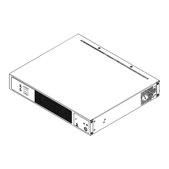
Page 9: Chassis Features
Chapter 1: Introduction 1.3 Chassis Features The SCE300-LED+ is a compact embedded 1U chassis for Mini ITX and Flex ATX motherboards. Front Features The front of the chassis includes the control panel. Figure 1-1. Chassis Front and Control Panel Control Panel Features Item Features Description... -
Page 10: Rear Features
SuperServer E300-9A-4CN10P User's Manual Rear Features The chassis rear holds input/output ports, described in Chapter 3. Figure 1-2. Rear Chassis View Rear Chassis Features Item Features Description The main power input applies or removes primary power from the power supply Power Input to the server but maintains standby power. -
Page 11: Motherboard Layout
Chapter 1: Introduction 1.4 Motherboard Layout The A2SDV-4C-LN10PF motherboard shares the same layout as the A2SDV-4C-LN8F motherboard pictured below but has one to three SATA3 ports and a dual 1GbE SFP LAN from i210 Controller. See the table on the following page for descriptions. For detailed descriptions, pin-out information and jumper settings, refer to Chapter 3. -
Page 12: Quick Reference Table
SuperServer E300-9A-4CN10P User's Manual Quick Reference Table Jumper Description Default Setting JBR1 BIOS Recovery Pins 1-2 (Normal) JBT1 CMOS Clear Open (Normal) C1, JI SMB to PCI-E Slots Enable/Disable Pins 2-3 (Disabled) JPG1 Onboard VGA Enable/Disable Pins 1-2 (Enabled) JPL1... - Page 13 Chapter 1: Introduction Connector Description JMD2 M.2 M-Key PCI-E3.0/SATA3 Slot Power Supply SMBus I C Header JPH1 4-pin Power Connector for HDD use JPW1 24-pin ATX Power Connector JPV1 4-pin 12V DC Power Connector (To provide alternative power for a special enclosure when the 24-pin ATX power is not in use.) JRT3 Thermal Diode 1...
-
Page 14: System Block Diagram
SuperServer E300-9A-4CN10P User's Manual System Block Diagram CPLD SMBUS2 LCMXO2-1200HC AST2400 COM1 HEADER UART1 FAN X5 TACHOMETER RTL8211F RJ45 RGMII2 GIGALAN TPM Header -4C SKUs: PCIE x2 SVID VR13 HSIO[14] , PCIE X1 USB 2.0 [0] PCIE X4 SLOT 6... -
Page 15: Server Installation And Setup
Chapter 1: Introduction 1.5 Server Installation and Setup The server is shipped with the onboard processor and the motherboard installed in the chassis. Several steps are necessary to begin using your server. You must add memory, mount the hard disk drive, and mount the system in place. Unpacking the System Inspect the box in which the system was shipped and note if it was damaged. -
Page 16: Installing Rack Mounting Brackets
SuperServer E300-9A-4CN10P User's Manual Installing Rack Mounting Brackets The chassis can be mounted in a rack using two rack brackets and a two-part power adapter shelf bracket (optional, MCP-290-30002-0B). 1. Attach the rack brackets using three screws through the holes in each bracket to secure the bracket to the chassis. -
Page 17: Mounting On A Wall
Chapter 1: Introduction Mounting on a Wall Optionally, the chassis can be mounted directly on a wall, using holes in the bottom. 1. Measure and install two screws into the wall where you want to mount the server. 2. Hang the server on the screws with the Input/Output ports on the top. Mounting Holes Figure 1-6. -
Page 18: Chapter 2 Maintenance And Component Installation
SuperServer E300-9A-4CN10P User's Manual Chapter 2 Maintenance and Component Installation This chapter provides instructions on installing and replacing main system components. To prevent compatibility issues, only use components that match the specifications and/or part numbers given. Installation or replacement of most components require that power first be removed from the system. -
Page 19: Accessing The System
Chapter 2 Maintenance and Component Installation 2.2 Accessing the System The SCE300-LED+ features a removable top cover to access to the inside of the chassis. Figure 2-1. Removing the Chassis Cover Removing the Top Cover 1. Power down the system as described in Section 2.1. 2. -
Page 20: Motherboard Components
Note: Check the Supermicro website for recommended memory modules. Memory Population Guidelines For optimal memory performance, follow the table below when populating memory. Populate... -
Page 21: Installing Memory
Chapter 2 Maintenance and Component Installation Installing Memory DIMM Installation 1. Insert the desired number of DIMMs into the memory slots, starting with DIMMA1, DIMMB1, DIMMA2, DIMMB2. For best performance, please use the memory modules of the same type and speed. Notches 2. -
Page 22: Motherboard Battery
SuperServer E300-9A-4CN10P User's Manual Motherboard Battery The motherboard uses non-volatile memory to retain system information when system power is removed. This memory is powered by a lithium battery residing on the motherboard. Figure 2-2. Installing the Onboard Battery Replacing the Battery 1. -
Page 23: Chassis Components
Chapter 2 Maintenance and Component Installation 2.4 Chassis Components Installing the Storage Drive The SCE300-LED+ can accommodate a single fixed 2.5" storage drive of 9.5 mm thickness. It is installed to a mounting tray inside the chassis. Use an enterprise quality drive. Figure 2-3. - Page 24 SuperServer E300-9A-4CN10P User's Manual 4. Return the drive tray assembly into the chassis, aligning the tabs of the tray with the slots in the chassis. Secure the tray to the chassis support bracket with the screws previously set aside. 5. Attach the cable SATA connector and to the motherboard connector. This cable carries both the SATA signal and the SATA power.
-
Page 25: System Cooling
Chapter 2 Maintenance and Component Installation System Cooling The SCE300-LED+ includes one replaceable 4-cm fan. An optional second fan can be purchased if needed. Replacing the System Fan 1. Power down the system as described in Section 2.1 and remove the AC power cord and the chassis cover. -
Page 26: Chapter 3 Motherboard Connections
SuperServer E300-9A-4CN10P User's Manual Chapter 3 Motherboard Connections This section describes the connections on the A2SDV-4C-LN10PF motherboard and provides pinout definitions. Note that depending on how the system is configured, not all connections are required. The LEDs on the motherboard are also described here. A motherboard layout indicating component locations may be found in Chapter 1. -
Page 27: Headers And Connectors
Chapter 3 Motherboard Connections JMD2 3.2 Headers and Connectors 12V DC Power Connector The 4-pin (JPV1) connector is used to provide alternative power for a special enclosure when BIOS LICENS the 24-pin ATX power is not in use. I-SATA1 I-SATA2 I-SATA3 I-SATA4 +12V 4-pin Power Pin Definitions SRW4... - Page 28 SuperServer E300-9A-4CN10P User's Manual Chassis Intrusion A Chassis Intrusion header is located at JL1 on the motherboard. Attach the appropriate cable from the chassis to inform you of a chassis intrusion when the chassis is opened. Refer to the table below for pin definitions.
- Page 29 Chapter 3 Motherboard Connections System Management Bus Header A System Management Bus header for additional slave devices or sensors is located at JSMB1. See the table below for pin definitions. SMBus Header Pin Definitions Pin# Definition Data Ground Clock BMC External I2C Header A System Management Bus header for IPMI 2.0 is located at JIPMB1.
- Page 30 SuperServer E300-9A-4CN10P User's Manual COM1 SRW2 JWD1 TPM/Port 80 Header A Trusted Platform Module (TPM)/Port 80 header is located at JTPM1 to provide TPM support and a Port 80 connection. Use this header to enhance system performance and data security.
- Page 31 Front RJ45 Link and Activity LED Header JFPCLED1 is the 1GbE RJ45 link and activity LED header. Attach a cable from this header to the Supermicro LED board (Part Number: FPB-FPE300-LED10) to display the status of the RJ45 LAN link and activity LED.
-
Page 32: Ports
SuperServer E300-9A-4CN10P User's Manual 3.3 Ports Figure 3-1. Rear Input/Output Ports Rear I/O Ports Description Description Description IPMI LAN Port LAN4 LAN7 USB1 LAN3 USB0 LAN6 LAN2 LAN5 LAN1 LAN8 VGA Port A VGA port is located on the I/O back panel. Use this port to connect to a compatible VGA display. - Page 33 Note: UID can also be triggered via IPMI on the motherboard. For more information on IPMI, please refer to the IPMI User's Guide posted on our website at https://www. supermicro.com/support/manuals/. UID Button UID LED Pin Definitions...
-
Page 34: Jumpers
SuperServer E300-9A-4CN10P User's Manual 3.4 Jumpers Explanation of Jumpers To modify the operation of the motherboard, jumpers are used to choose between optional settings. Jumpers create shorts between two pins to change the function associated with it. Pin 1 is identified with a square solder pad on the printed circuit board. See the motherboard layout page for jumper locations. - Page 35 Chapter 3 Motherboard Connections Watch Dog JWD1 controls the Watch Dog function. Watch Dog is a monitor that can reboot the system when a software application hangs. Jumping pins 1-2 will cause Watch Dog to reset the system if an application hangs. Jumping pins 2-3 will generate a non-maskable interrupt signal for the application that hangs.
- Page 36 SuperServer E300-9A-4CN10P User's Manual VGA Enable/Disable Use jumper JPG1 to enable or disable the onboard VGA connector. Refer to the table below for jumper settings. VGA Enable/Disable Jumper Settings Jumper Setting Definition Pins 1-2 Enabled (Default) Pins 2-3 Disabled BIOS Recovery Close pins 2-3 of jumper JBR1 for BIOS recovery.
-
Page 37: Led Indicators
Chapter 3 Motherboard Connections 3.5 LED Indicators LAN LEDs Eight RJ45 LAN ports and two SFP LAN ports are located on the I/O back panel. Each Ethernet LAN port has two LEDs. One LED indicates activity, while the other Link LED may be green, amber, or off to indicate the speed of the connection. -
Page 38: Chapter 4 Software
You must first configure RAID settings (if using RAID) before you install the Windows OS and the software drivers. To configure RAID settings, please refer to the RAID Configuration User Guides posted on our website at www.supermicro.com/support/manuals. Installing the Windows OS for a RAID System 1. -
Page 39: Driver Installation
The Supermicro website contains drivers and utilities for your system at https://www. supermicro.com/wftp/driver. Some of these must be installed, such as the chipset driver. After accessing the website, go into the CDR_Images (in the parent directory of the above link) and locate the ISO file for your motherboard. Download this file to create a DVD of the drivers and utilities it contains. -
Page 40: Superdoctor ® 5
4.3 SuperDoctor ® The Supermicro SuperDoctor 5 is a program that functions in a command-line or web-based interface for Windows and Linux operating systems. The program monitors such system health information as CPU temperature, system voltages, system power consumption, fan speed, and provides alerts via email or Simple Network Management Protocol (SNMP). -
Page 41: Ipmi
The A2SDV-4C-LN10PF supports the Intelligent Platform Management Interface (IPMI). IPMI is used to provide remote access, monitoring and management. There are several BIOS settings that are related to IPMI. For general documentation and information on IPMI, please visit our website at: http://www.supermicro.com/products/nfo/IPMI.cfm. -
Page 42: Chapter 5 Bios
SuperServer E300-9A-4CN10P User's Manual Chapter 5 BIOS 5.1 Introduction This chapter describes the AMI BIOS setup utility for the A2SDV-4C-LN10PF. The AMI ROM BIOS is stored in a Flash EEPROM and can be easily updated. This chapter describes the basic navigation of the AMI BIOS utility setup screens. -
Page 43: Main Setup
Note: The time is in the 24-hour format. For example, 5:30 P.M. appears as 17:30:00. The date's default value is the BIOS build date after RTC reset. Supermicro A2SDV-4C-LN10PF BIOS Version This feature displays the version of the BIOS ROM used in the system. - Page 44 SuperServer E300-9A-4CN10P User's Manual Memory Information Total Memory This feature displays the total size of memory available in the system. Memory Speed This feature displays the default speed of the memory modules installed in the system.
-
Page 45: Advanced
Chapter 5 BIOS 5.3 Advanced Use this menu to configure Advanced settings. Warning: Take caution when changing the Advanced settings. An incorrect value, a very high DRAM frequency or an incorrect BIOS timing setting may cause the system to malfunction. When this occurs, restore to default manufacturer settings. - Page 46 SuperServer E300-9A-4CN10P User's Manual Power Configuration Watch Dog Function If enabled, the Watch Dog timer will allow the system to reboot when it is inactive for more than 5 minutes. The options are Disabled and Enabled. Power Button Function This feature controls how the system shuts down when the power button is pressed. Select 4 Seconds Override for the user to power off the system after pressing and holding the power button for 4 seconds or longer.
- Page 47 Chapter 5 BIOS Select Enable to activate TM1 support for system thermal monitoring. TM1 allows the CPU to regulate its power consumption based upon the modulation of the CPU Internal clock when the CPU temperature reaches a pre-defined overheating threshold. The options are Disable and Enable.
- Page 48 SuperServer E300-9A-4CN10P User's Manual L2 Prefetcher If enabled, the hardware prefetcher will prefetch streams of data and instructions from the main memory to the L2 cache to improve CPU performance. The options are Enable and Disable. ACPI 3.0 T-States Select Enable to support ACPI (Advanced Configuration and Power Interface) 3.0 T-States to determine how the processor will report to the operating system during CPU-Throttling states.
- Page 49 Chapter 5 BIOS Lock PACKAGE_RAPL_LIMIT Use this feature to lock the MSR 0x610 bit. The options are Disable and Enable. *If the feature above is set to Disable, the next three features will be available for configuration: PL1 Time Window Use this feature to define the Running Average Power Limit (RAPL) time window 1 in miliseconds.
- Page 50 SuperServer E300-9A-4CN10P User's Manual VT-d Interrupt remapping Use this feature to enable Interrupt Remapping support, which detects and controls external interrupt requests. The options are Disabled and Enabled. Fast Boot Use this feature to enable or disable fast path through the memory reference code. The options are Disabled and Enabled.
- Page 51 Chapter 5 BIOS Demand Scrub Enable Demand Scrubbing is a process that allows the CPU to correct correctable memory errors found in a memory module. When the CPU or I/O issues a demand-read command, and the read data from memory turns out to be a correctable error, the error is corrected and sent to the requestor (the original source).
- Page 52 SuperServer E300-9A-4CN10P User's Manual South Bridge Configuration South Bridge Configuration • USB Module Version • USB Controllers: • USB Devices: Legacy USB Support Select Enabled to support onboard legacy USB devices. Select Auto to disable legacy support if there are no legacy USB devices present. Select Disable to have all USB devices available for EFI applications only.
- Page 53 Chapter 5 BIOS SATA Configuration SATA0 SATA 0 Enable controller This item enables or disables the onboard SATA controller supported by the processor. The options are Enabled and Disabled. SATA 0 ALPM When this feature is set to Enabled, the SATA AHCI controller manages the power usage of the SATA link.
- Page 54 SuperServer E300-9A-4CN10P User's Manual SATA1 SATA 1 Enable controller This item enables or disables the onboard SATA controller supported by the processor. The options are Enabled and Disabled. SATA 1 ALPM When this feature is set to Enabled, the SATA AHCI controller manages the power usage of the SATA link.
- Page 55 Chapter 5 BIOS Intel Server Platform Services General ME Configuration • Operational Firmware Version • ME Firmware Type • Backup Firmware Version • Recovery Firmware Version • ME Firmware Features • ME Firmware Status #1 • ME Firmware Status #2 •...
- Page 56 SuperServer E300-9A-4CN10P User's Manual Maximum Payload Select Auto for the system BIOS to automatically set the maximum payload value for a PCI-E device to enhance system performance. The options are Auto, 128 Bytes, 256 Bytes, 512 Bytes, 1024 Bytes, 2048 Bytes, and 4096 Bytes.
- Page 57 Chapter 5 BIOS Network Stack Select Enabled to enable PXE (Preboot Execution Environment) or UEFI (Unified Extensible Firmware Interface) for network stack support. The options are Enabled and Disabled. *If "Network Stack" is set to Enabled, the next four features will be available for configuration: Ipv4 PXE Support Use this feature to enable Ipv4 PXE Boot Support.
- Page 58 SuperServer E300-9A-4CN10P User's Manual Serial Port 1 Change Settings This feature specifies the base I/O port address and the Interrupt Request address of Serial Port 1. Select Auto for the BIOS to automatically assign the base I/O and IRQ address to a serial port specified.
- Page 59 Chapter 5 BIOS COM1 Stop Bits A stop bit indicates the end of a serial data packet. Select 1 Stop Bit for standard serial data communication. Select 2 Stop Bits if slower devices are used. The options are 1 and 2. COM1 Flow Control Use this item to set the flow control for Console Redirection to prevent data loss caused by buffer overflow.
- Page 60 SuperServer E300-9A-4CN10P User's Manual SOL Terminal Type Use this feature to select the target terminal emulation type for Console Redirection. Select VT100 to use the ASCII Character set. Select VT100+ to add color and function key support. Select ANSI to use the Extended ASCII Character Set. Select VT-UTF8 to use UTF8 encoding to map Unicode characters into one or more bytes.
- Page 61 Chapter 5 BIOS SOL Resolution 100x31 Select Enabled for extended-terminal resolution support. The options are Disabled and Enabled. SOL Putty KeyPad This feature selects Function Keys and KeyPad settings for Putty, which is a terminal emulator designed for the Windows OS. The options are VT100, LINUX, XTERMR6, SCO, ESCN, and VT400.
- Page 62 SuperServer E300-9A-4CN10P User's Manual Flow Control Use this feature to set the flow control for Console Redirection to prevent data loss caused by buffer overflow. Send a "Stop" signal to stop sending data when the receiving buffer is full. Send a "Start" signal to start sending data when the receiving buffer is empty. The options are None, Hardware RTS/CTS, and Software Xon/Xoff.
- Page 63 Chapter 5 BIOS Pending operation Use this item to schedule a TPM-related operation to be performed by a security device for system data integrity. Your system will reboot to carry out a pending TPM operation. The options are None and TPM Clear. Note: Reboot the computer to change the state of the security device.
- Page 64 SuperServer E300-9A-4CN10P User's Manual SHA256 PCR Bank Use this item to disable or enable the SHA256 Platform Configuration Register (PCR) bank for the installed TPM device. The options are Disabled and Enabled. Pending operation Use this item to schedule a TPM-related operation to be performed by a security device for system data integrity.
- Page 65 Chapter 5 BIOS iSCSI Configuration iSCSI Initiator Name This feature allows the user to enter the unique name of the iSCSI Initiator in IQN format. Once the name of the iSCSI Initiator is entered into the system, configure the proper settings for the following items.
- Page 66 SuperServer E300-9A-4CN10P User's Manual UEFI Driver This feature displays the UEFI driver version. Adapter PBA This feature displays the Processor Bus Adapter (PBA) model number. The PBA number is a nine digit number (i.e., 010B00-000) located near the serial number.
-
Page 67: Event Logs
Chapter 5 BIOS 5.4 Event Logs Use this menu to configure Event Log settings. Change SMBIOS Event Log Settings Enabling/Disabling Options PCIe ELog Support Use this feature to enable or disable PCI-e error logging suport. The options are Disabled and Enabled. Memory ELog Support Use this feature to enable or disable memory error logging suport. - Page 68 SuperServer E300-9A-4CN10P User's Manual Erasing Settings Erase Event Log Select Enabled to erase all error events in the SMBIOS (System Management BIOS) log before an event logging is initialized at bootup. The options are No, Yes, Next reset, and Yes, Every reset.
-
Page 69: Ipmi
Chapter 5 BIOS 5.5 IPMI Use this menu to configure Intelligent Platform Management Interface (IPMI) settings. BMC Firmware Revision This feature indicates the IPMI firmware revision used in your system. IPMI Status This feature indicates the status of the IPMI firmware installed in your system. System Event Log Enabling/Disabling Options SEL Components... - Page 70 SuperServer E300-9A-4CN10P User's Manual When SEL is Full This feature allows the user to determine what the BIOS should do when the system event log is full. Select Erase Immediately to erase all events in the log when the system event log is full.
- Page 71 Chapter 5 BIOS Station MAC Address This feature displays the Station MAC address for this computer. Mac addresses are 6 two-digit hexadecimal numbers. Gateway IP Address This feature displays the Gateway IP address for this computer. This should be in decimal and in dotted quad form (i.e., 192.168.10.253).
-
Page 72: Security
SuperServer E300-9A-4CN10P User's Manual 5.6 Security Use this menu to configure Security settings. Password Check Select Setup for the system to check for a password at Setup. Select Always for the system to check for a password at bootup or upon entering the BIOS Setup utility. The options are Setup and Always. - Page 73 Chapter 5 BIOS Enable Secure Boot Select Enable for secure boot support to ensure system security at bootup. The options are Disabled and Enabled. Secure Boot Mode This feature allows the user to select the desired secure boot mode for the system. The options are Standard and Custom.
- Page 74 SuperServer E300-9A-4CN10P User's Manual Erase Select Yes to delete the PK from NVRAM. The options are Yes and No. Key Exchange Keys Save to File Select Yes to save the KEK to a storage device. Set New Select Yes to load the KEK from the manufacturer's defaults. Select No to load the KEK from a file.
- Page 75 Chapter 5 BIOS Append Select Yes to add the dbx from the manufacturer's defaults to the existing dbx. Select No to load the dbx from a file. The options are Yes and No. Erase Select Yes to delete the dbx from NVRAM. The options are Yes and No. ...
-
Page 76: Boot
SuperServer E300-9A-4CN10P User's Manual 5.7 Boot Use this menu to configure Boot settings: Boot mode select Use this feature to select the boot mode for bootable devices in the system. The options are LEGACY, UEFI, and DUAL. Fixed Boot Order Priorities This option prioritizes the order of bootable devices that the system boots from. - Page 77 Chapter 5 BIOS • LEGACY/UEFI/DUAL Boot Option #8 • LEGACY/UEFI/DUAL Boot Option #9 UEFI Application Boot Priorities • Boot Option # - This feature sets the system boot order of detected devices. The options are [the list of detected boot device(s)] and Disable. ...
-
Page 78: Save & Exit
SuperServer E300-9A-4CN10P User's Manual 5.8 Save & Exit Use this menu to save settings and exit the BIOS. Save Options Save Changes and Reset When you have completed the system configuration changes, select this option to save all changes made and reset the system. - Page 79 Chapter 5 BIOS Default Options Restore Optimized Defaults To set this feature, select Restore Optimized Defaults and press <Enter>. These are factory settings designed for maximum system performance but not for maximum stability. Save as User Defaults To set this feature, select Save as User Defaults from the Exit menu and press <Enter>. This enables the user to save any changes to the BIOS setup for future use.
-
Page 80: Appendix A Bios Error Codes
When BIOS performs the Power On Self Test, it writes checkpoint codes to I/O port 0080h. If the computer cannot complete the boot process, a diagnostic card can be attached to the computer to read I/O port 0080h (Supermicro p/n AOC-LPC80-20). For information on AMI updates, please refer to http://www.ami.com/products/. -
Page 81: Appendix B Standardized Warning Statements For Dc Systems
Supermicro's Technical Support department for assistance. Only certified technicians should attempt to install or configure components. Read this appendix in its entirety before installing or configuring components in the Supermicro chassis. These warnings may also be found on our website at http://www.supermicro.com/about/... - Page 82 Appendix B: Standardized Warning Statements Warnung WICHTIGE SICHERHEITSHINWEISE Dieses Warnsymbol bedeutet Gefahr. Sie befinden sich in einer Situation, die zu Verletzungen führen kann. Machen Sie sich vor der Arbeit mit Geräten mit den Gefahren elektrischer Schaltungen und den üblichen Verfahren zur Vorbeugung vor Unfällen vertraut. Suchen Sie mit der am Ende jeder Warnung angegebenen Anweisungsnummer nach der jeweiligen Übersetzung in den übersetzten Sicherheitshinweisen, die zusammen mit diesem Gerät ausgeliefert wurden.
- Page 83 SuperServer E300-9A-4CN10P User's Manual . ٌ ا ك ً ف حالة و ٌ يك أى تتسبب ف اصابة جسذ ة ٌ هذا الزهز ع ٌ خطز !تحذ ز قبل أى تعول عىل أي هعذات،يك عىل علن بالوخاطز ال ا ٌجوة عي الذوائز...
- Page 84 Appendix B: Standardized Warning Statements Warnung Vor dem Anschließen des Systems an die Stromquelle die Installationsanweisungen lesen. ¡Advertencia! Lea las instrucciones de instalación antes de conectar el sistema a la red de alimentación. Attention Avant de brancher le système sur la source d'alimentation, consulter les directives d'installation. .יש...
- Page 85 SuperServer E300-9A-4CN10P User's Manual Warnung Dieses Produkt ist darauf angewiesen, dass im Gebäude ein Kurzschluss- bzw. Überstromschutz installiert ist. Stellen Sie sicher, dass der Nennwert der Schutzvorrichtung nicht mehr als: 60VDC, 20A beträgt. ¡Advertencia! Este equipo utiliza el sistema de protección contra cortocircuitos (o sobrecorrientes) del edificio.
- Page 86 Appendix B: Standardized Warning Statements Power Disconnection Warning Warning! The system must be disconnected from all sources of power and the power cord removed from the power supply module(s) before accessing the chassis interior to install or remove system components. 電源切断の警告...
- Page 87 SuperServer E300-9A-4CN10P User's Manual يجب فصم اننظاو من جميع مصادر انطاقت وإ ز انت سهك انكهرباء من وحدة امداد انطاقت قبم انىصىل إىن امنناطق انداخهيت نههيكم نتثبيج أو إ ز انت مكىناث الجهاز 경고! 시스템에 부품들을 장착하거나 제거하기 위해서는 섀시 내부에 접근하기 전에 반드시 전원...
- Page 88 Appendix B: Standardized Warning Statements Attention Il est vivement recommandé de confier l'installation, le remplacement et la maintenance de ces équipements à des personnels qualifiés et expérimentés. !אזהרה .צוות מוסמך בלבד רשאי להתקין, להחליף את הציוד או לתת שירות עבור הציוד واملدربيه...
- Page 89 SuperServer E300-9A-4CN10P User's Manual Warnung Diese Einheit ist zur Installation in Bereichen mit beschränktem Zutritt vorgesehen. Der Zutritt zu derartigen Bereichen ist nur mit einem Spezialwerkzeug, Schloss und Schlüssel oder einer sonstigen Sicherheitsvorkehrung möglich. ¡Advertencia! Esta unidad ha sido diseñada para instalación en áreas de acceso restringido. Sólo puede obtenerse acceso a una de estas áreas mediante la utilización de una herramienta especial,...
- Page 90 Appendix B: Standardized Warning Statements Battery Handling Warning! There is the danger of explosion if the battery is replaced incorrectly. Replace the battery only with the same or equivalent type recommended by the manufacturer. Dispose of used batteries according to the manufacturer's instructions 電池の取り扱い...
- Page 91 SuperServer E300-9A-4CN10P User's Manual هناك خطر من انفجار يف حالة اسحبذال البطارية بطريقة غري صحيحة فعليل اسحبذال البطارية فقط بنفس النىع أو ما يعادلها مام أوصث به الرشمة املصنعة جخلص من البطاريات املسحعملة وفقا لحعليامت الرشمة الصانعة 경고! 배터리가 올바르게 교체되지 않으면 폭발의 위험이 있습니다. 기존 배터리와 동일하거나 제...
- Page 92 Appendix B: Standardized Warning Statements ¡Advertencia! Puede que esta unidad tenga más de una conexión para fuentes de alimentación. Para cortar por completo el suministro de energía, deben desconectarse todas las conexiones. Attention Cette unité peut avoir plus d'une connexion d'alimentation. Pour supprimer toute tension et tout courant électrique de l'unité, toutes les connexions d'alimentation doivent être débranchées.
- Page 93 SuperServer E300-9A-4CN10P User's Manual Backplane Voltage Warning! Hazardous voltage or energy is present on the backplane when the system is operating. Use caution when servicing. バックプレーンの電圧 システムの稼働中は危険な電圧または電力が、 バックプレーン上にかかっています。 修理する際には注意く ださい。 警告 当系统正在进行时,背板上有很危险的电压或能量,进行维修时务必小心。 警告 當系統正在進行時,背板上有危險的電壓或能量,進行維修時務必小心。 Warnung Wenn das System in Betrieb ist, treten auf der Rückwandplatine gefährliche Spannungen oder Energien auf.
- Page 94 Appendix B: Standardized Warning Statements هناك خطز مه التيار الكهزبايئ أوالطاقة املىجىدة عىل اللىحة عندما يكىن النظام يعمل كه حذ ر ا عند خدمة هذا الجهاس 경고! 시스템이 동작 중일 때 후면판 (Backplane)에는 위험한 전압이나 에너지가 발생 합니다. 서비스 작업 시 주의하십시오. Waarschuwing Een gevaarlijke spanning of energie is aanwezig op de backplane wanneer het systeem in gebruik is.
- Page 95 SuperServer E300-9A-4CN10P User's Manual תיאום חוקי החשמל הארצי !אזהרה .התקנת הציוד חייבת להיות תואמת לחוקי החשמל המקומיים והארציים تركيب املعدات الكهربائية يجب أن ميتثل للقىاويه املحلية والىطىية املتعلقة بالكهرباء 경고! 현 지역 및 국가의 전기 규정에 따라 장비를 설치해야 합니다.
- Page 96 Appendix B: Standardized Warning Statements Attention La mise au rebut ou le recyclage de ce produit sont généralement soumis à des lois et/ou directives de respect de l'environnement. Renseignez-vous auprès de l'organisme compétent. סילוק המוצר !אזהרה .סילוק סופי של מוצר זה חייב להיות בהתאם להנחיות וחוקי המדינה التخلص...
- Page 97 SuperServer E300-9A-4CN10P User's Manual Warnung Gefährlich Bewegende Teile. Von den bewegenden Lüfterblätter fern halten. Die Lüfter drehen sich u. U. noch, wenn die Lüfterbaugruppe aus dem Chassis genommen wird. Halten Sie Finger, Schraubendreher und andere Gegenstände von den Öffnungen des Lüftergehäuses entfernt.
- Page 98 Appendix B: Standardized Warning Statements DC Power Supply Warning! When stranded wiring is required, use approved wiring terminations, such as closedloop or spade-type with upturned lugs. These terminations should be the appropriate size for the wires and should clamp both the insulation and conductor. 警告...
- Page 99 SuperServer E300-9A-4CN10P User's Manual وأ ةقلغم ةقلح لثم ،اهيلع ةقفاوملا ءاهنإ كالسألا مادختساو ،لبسلا مهب تعطقت نيذلا كالسألا ابولطم نوكي امدنع بجيو كالسألل بسانملا مجحلا نوكي تاءاهنإلا هذهل يغبنيو .ةبولقم تاورعلا عم عونلا ةيقيقحلا اهئامسأب ءايشألا .لصومو لزعلا نم لك حبك...
- Page 100 Appendix B: Standardized Warning Statements Warnung Vor Ausführung der folgenden Vorgänge ist sicherzustellen, daß die Gleichstromschaltung keinen Strom erhält. ¡Advertencia! Antes de proceder con los siguientes pasos, comprobar que la alimentación del circuito de corriente continua (CC) esté cortada (OFF). Attention Avant de pratiquer l'une quelconque des procédures ci-dessous, vérifier que le circuit en courant continu n'est plus sous tension.
- Page 101 SuperServer E300-9A-4CN10P User's Manual Hazardous Voltage or Energy Present on DC Power Terminals Warning! Hazardous voltage or energy may be present on DC power terminals. Always replace cover when terminals are not in service. Be sure uninsulated conductors are not accessible when cover is in place.
- Page 102 Appendix B: Standardized Warning Statements امدنع امئاد ءاطغ لادبتسا .ةمصاعلا ةقاطلا تاطحم ىلع ةدوجوم نوكت ةقاطلا وأ ةرطخلا دهجلا دق ءاطغلا امدنع اهيلإ لوصولا نكمي ال لوزعم ريغ تالصوملا هيف كش ال امم .ةمدخلا يف تسيل تاطحملا .هناكم يف 주의! DC전원...
-
Page 103: Appendix C System Specifications
Appendix C: System Specifications Appendix C System Specifications Processors Single Intel® Atom C3558 (System on a Chip) 4 Cores, 4 Threads, 2.2 GHz,16W Memory Four DIMM slots, DDR4 2400MHz up to 256GB RDIMM, or 64GB for ECC/Non-ECC UDIMM SATA Controller SoC controller for four SATA3 (6Gbps) ports Drive Bay One 2.5"... -
Page 104: Appendix D Uefi Bios Recovery
Warning: Do not upgrade the BIOS unless your system has a BIOS-related issue. Flashing the wrong BIOS can cause irreparable damage to the system. In no event shall Supermicro be liable for direct, indirect, special, incidental, or consequential damages arising from a BIOS update. - Page 105 Directory of a USB device or a writeable CD/DVD. Note: If you cannot locate the "Super.ROM" file in your driver disk, visit our website at www.supermicro.com to download the BIOS image into a USB flash device and rename it "Super.ROM" for BIOS recovery use.
- Page 106 E300-9A-4CN10P User's Manual 4. After locating the new BIOS binary image, the system will enter the BIOS Recovery menu as shown below. Note: At this point, you may decide if you want to start the BIOS recovery. If you decide to proceed with BIOS recovery, follow the procedures below.
- Page 107 Appendix D: UEFI BIOS Recovery 6. After the BIOS recovery process is completed, press any key to reboot the system. 7. Using a different system, extract the BIOS package into a USB flash drive. 8. Press <Del> continuously to enter the BIOS setup utility. Set the item, Boot Option #1, to [UEFI AP:UEFI: Built-in EFI Shell].
- Page 108 E300-9A-4CN10P User's Manual 9. When the UEFI Shell prompt appears, type fs# to change the device directory path. Go to the directory which contains the BIOS package extracted earlier from Step 7. Enter flash.nsh BIOSname.### at the prompt to start the BIOS update process. Note: Do not interrupt this process until the BIOS flashing is complete.
-
Page 109: Appendix E Traditional Chinese Version Safety Warnings
Appendix E: Traditional Chinese Version Safety Warnings Traditional Chinese Version Appendix E Safety Warnings Traditional Chinese Version Safety Warnings Additional Traditional Chinese Version warning statements are included here in this appendix. 安全警告 (注意這些警告標誌) 以下的警告標誌對於安全使用本設備非常重要,可以避免操作人員遭遇危險,以及財產 受到任何損失。 錯誤使用本機器或忽視這本手冊,所引起的傷害或損失等級分類如下: Warning! (警告) 此注意標誌提醒未能依照正確指示使用機器,可能導致生 命危險 或造成嚴重傷害。 Caution ( 注意... - Page 110 SuperServer E300-9A-4CN10P User's Manual Traditional Chinese Version Safety Warnings 1. 勿使用多孔插座或延長線,否則可能造成溫度過高而引起火災。 2. 勿在電源線放置重物,否則可能引起火災或受到電擊。 3. 勿踏在電源線上,及勿損傷或任意處理電源線, 否則可能引起火災或 受到電擊。 4. 勿綁住或紮緊電源線,否則可能引起火災或受到電擊。 5. 勿將花瓶、花盆或盛水容器放在機器上,如果水滴濺出,可能引起火 災或受 到電擊 1. 機器如果產生怪味或不正常聲響,必需立即關閉機器電源開關,然後 從插座 取下插頭 2. 絕對不可以沾濕的手插拔插頭,否則可能受到電擊。 3. 插頭必須確實插妥在插座上,如果未能妥善插好,可能會引起火災。 4. 僅可使用機器所附電源插頭。 拔取電源線時,確實抓住插頭部位,否則導致插頭破裂可能引起火 災或受到電 擊。 不可企圖拆解或擅自修改機器,否則可能引起火災或受到電擊。 不可將機器安裝在下列場所: 1. 濕氣高及多灰塵的地方。...
- Page 111 Appendix E: Traditional Chinese Version Safety Warnings 警告使用者: 這是乙類的資訊產品,在居住的環境中使用時,可能會造成射頻 干擾,在這種情況下,使用者會被要求採取某些適當的對策...
Need help?
Do you have a question about the SuperServer E300-9A-4CN10P and is the answer not in the manual?
Questions and answers