Table of Contents
Advertisement
Advertisement
Table of Contents

Related Manuals for Supermicro SuperServer E300-8D


Summary of Contents for Supermicro SuperServer E300-8D
- Page 1 ® UpER ERvER E300-8D USER’S MANUAL Revision 1.0c...
- Page 2 State of California, USA. The State of California, County of Santa Clara shall be the exclusive venue for the resolution of any such disputes. Supermicro's total liability for all claims will not exceed the price paid for the hardware product.
-
Page 3: About This Manual
Preface About this Manual This manual is written for professional system integrators and PC technicians. It provides information for the installation and use of the SuperServer E300-8D. Installation and maintenance should be performed by experienced technicians only. Notes For your system to work properly, please follow the links below to download all necessary drivers/utilities and the user’s manual for your server. -
Page 4: Table Of Contents
SuperServer E300-8D User's Manual Contents Chapter 1 Introduction 1.1 Overview ..........................7 1.2 System Features ........................8 1.3 Chassis Features .........................9 Front Features ........................9 Rear Features ........................10 1.4 Motherboard Layout ......................11 Quick Reference .......................12 System Block Diagram ......................14 1-5 Server Installation and Setup .....................15 Unpacking the System ......................15... - Page 5 Preface Chapter 3 Motherboard Connections 3.1 Power Connections ......................27 3.2 Headers and Connectors ....................28 Control Panel ........................32 3.3 Ports ...........................35 3.4 Jumpers ..........................36 Explanation of Jumpers.....................36 3.5 LED Indicators ........................39 3.6 SATA Connections ......................41 Chapter 4 Software 4.1 Driver Installation ........................42 4.2 SuperDoctor 5 ........................43 ®...
-
Page 6: Contacting Supermicro
SuperServer E300-8D User's Manual Contacting Supermicro Headquarters Address: Super Micro Computer, Inc. 980 Rock Ave. San Jose, CA 95131 U.S.A. Tel: +1 (408) 503-8000 Fax: +1 (408) 503-8008 Email: marketing@supermicro.com (General Information) support@supermicro.com (Technical Support) Website: www.supermicro.com Europe Address: Super Micro Computer B.V. -
Page 7: Chapter 1 Introduction
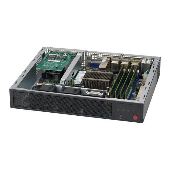
Introduction 1.1 Overview The SuperServer E300-8D is a compact, embedded system comprised of the SCE300 chassis and the X10SDV-TP8F single processor motherboard. Refer to our website for information on operating systems that have been certified for use with the system (www.supermicro.com). -
Page 8: System Features
SuperServer E300-8D User's Manual 1.2 System Features The following table provides an overview of the main features of the E300-8D. Please refer to Appendix C for additional specifications. System Features Motherboard X10SDV-TP8F Chassis Compact Embedded Mini ITX Box, SCE300 Intel Xeon D-1518 SoC (System on a Chip) in FCBGA1667 format; 4-Core, 8 Threads, 35W Memory Four DDR4 DIMM sockets;... -
Page 9: Chassis Features
Chapter 1: Introduction 1.3 Chassis Features The SCE300 is a compact embedded 1U chassis for Mini ITX and a Flex ATX motherboard. Front Features The front of the chassis includes the control panel. Figure 1-1. Chassis Front and Control Panel Control Panel Features Item Features... -
Page 10: Rear Features
SuperServer E300-8D User's Manual Information LED Status Description Continuously on and An overheat condition has occurred. (This may be caused by cable congestion.) Blinking red (1Hz) Fan failure, check for an inoperative fan. Power failure, check for a non-operational power Blinking red (0.25Hz) -
Page 11: Motherboard Layout
Chapter 1: Introduction 1.4 Motherboard Layout Below is a layout of the X10SDV-TP8F with jumper, connector and LED locations shown. See the table on the following page for descriptions. For detailed descriptions, pin-out information and jumper settings, refer to Chapter 4. LAN7/8 JPL3 LAN5/6... -
Page 12: Quick Reference
SuperServer E300-8D User's Manual Quick Reference Jumper Description Default Setting JBR1 BIOS Recovery Pins 1-2 (Normal) JBT1 CMOS Clear Open: Normal, Short: Clear CMOS JI2C1/JI2C2 SMB to PCI-Exp. Slots Pins 2-3 (Disabled) JPG1 VGA Enable Pins 1-2 (Enabled) JPL1 LAN1 Enable... - Page 13 Chapter 1: Introduction Connector Description JTPM1 Trusted Platform Module (TPM)/Port 80 Connector LAN1-LAN8 Gigabit Ethernet (RJ45) Ports LAN1-LAN6 10Gigabit Ethernet (SFP+) Ports LAN7-LAN8 M2-SRW1 - M2-SRW3 M.2 Mounting Screws MP-SRW1 - SRW2 PCI-E 2.0 X1 / I-SATA5 Slot Mounting Screws SLOT6, SLOT7 CPU PCI-E 3.0 x8 Slot Unit ID Button...
-
Page 14: System Block Diagram
SuperServer E300-8D User's Manual System Block Diagram DDR4 1600/1866/2133 PCIE 3.0 x8 JPCIE1 PCIE 3.0 x8 PCIE 3.0 x8 JPCIE2 PCIE 3.0 x8 MINI-SAS HD PROCESSOR PCIE 3.0 x3 SAS2 LSI SAS2116 PCIE 3.0 x3 M.2 CONN SFP+ iXFI INPHI CS4227... -
Page 15: Server Installation And Setup
Chapter 1: Introduction 1-5 Server Installation and Setup The server is shipped with the onboard processor and the motherboard installed in the chassis. Several steps are necessary to begin using your server. You must add memory, mount the hard disk drive, and mount the system in place. Unpacking the System Inspect the box in which the system was shipped and note if it was damaged. -
Page 16: Installing Rack Mounting Brackets
SuperServer E300-8D User's Manual Installing Rack Mounting Brackets The chassis can be mounted in a rack using two rack brackets and a two-part power adapter shelf bracket (optional, MCP-290-30002-0B). 1. Attach the rack brackets using three screws through the holes in each bracket to secure the bracket to the chassis. -
Page 17: Chapter 2 Maintenance And Component Installation
Chapter 2 Maintenance and Component Installation Chapter 2 Maintenance and Component Installation This chapter provides instructions on installing and replacing main system components. To prevent compatibility issues, only use components that match the specifications and/or part numbers given. Installation or replacement of most components require that power first be removed from the system. -
Page 18: Accessing The System
SuperServer E300-8D User's Manual 2.2 Accessing the System The SCE300 features a removable top cover to access to the inside of the chassis. Figure 2-1. Removing the Chassis Cover Removing the Top Cover 1. Power down the system as described in section 2.1. -
Page 19: Motherboard Components
16GB 16GB 32GB 16GB 16GB 16GB 16GB 64GB 32GB 32GB 64GB 32GB 32GB 32GB 32GB 128GB Check the Supermicro website for a list of memory modules that have been validated. Use memory modules of the same type, speed and frequency. -
Page 20: Installing Memory
SuperServer E300-8D User's Manual Installing Memory When installing memory modules, the DIMM slots should be populated in the following order: DIMMA1, DIMMB1, then DIMMA2, DIMMB2. • Always use DDR4 DIMM modules of the same size, type and speed. Mixing memory modules of different types and speeds is not allowed. -
Page 21: Solid State Storage
Chapter 2 Maintenance and Component Installation Solid State Storage This motherboard supports two internally mounted solid state storage cards: • One mini-PCIe mSATA slot • One M.2 slot supporting SATA Mini-PCIe Figure 2-2. Installing a Mini-PCIe mSATA Card and an M.2 Card... -
Page 22: Mini-Pcie Msata
SuperServer E300-8D User's Manual Mini-PCIe mSATA The X10SDV-TP8F supports a mini-PCIe mSATA SSD card. The mSATA is mux with the I-SATA5. Installing an mSATA Mini-PCIe Card 1. Access the motherboard and locate the mSATA mini PCIe connector (Figure 1.3, JMP1) 2. -
Page 23: Motherboard Battery
Chapter 2 Maintenance and Component Installation Motherboard Battery The motherboard uses non-volatile memory to retain system information when system power is removed. This memory is powered by a lithium battery residing on the motherboard. Figure 2-3. Installing the Onboard Battery Replacing the Battery 1. -
Page 24: Chassis Components
SuperServer E300-8D User's Manual 2.4 Chassis Components Installing the Storage Drive The SCE300 can accommodate a single fixed 2.5" storage drive of 9.5 mm thickness. It is installed to a mounting tray inside the chassis. Use an enterprise quality drive. -
Page 25: Installing The Riser Card
Chapter 2 Maintenance and Component Installation 4. Return the drive tray assembly into the chassis, aligning the tabs of the tray with the slots in the chassis. Secure the tray to the chassis support bracket with the screws previously set aside. 5. -
Page 26: System Cooling
SuperServer E300-8D User's Manual System Cooling The SCE300 includes two replaceable 4-cm fans. An optional third fan can be purchased. Replacing the System Fan 1. Power down the system as described in section 2.1 and remove the AC power cord and the chassis cover. -
Page 27: Chapter 3 Motherboard Connections
Chapter 3 Motherboard Connections Chapter 3 Motherboard Connections This section describes the connections on the X10SDV-TP8F motherboard and provides pinout definitions. Note that depending on how the system is configured, not all connections are required. The LEDs on the motherboard are also described here. A motherboard layout indicating component locations may be found in Chapter 1. -
Page 28: Headers And Connectors
SuperServer E300-8D User's Manual 3.2 Headers and Connectors Fan Headers This motherboard has six 4-pin fan headers. Although pins 1-3 of the fan headers are backward compatible with the traditional 3-pin fans, you can use 4-pin fans to take advantage of the fan speed control via Pulse Width Modulation through the BMC. - Page 29 Chapter 3 Motherboard Connections Disk-On-Module Power Connector The Disk-On-Module (DOM) power connectors (JSD1 and JSD2) provide 5V power to a solid state DOM storage device connected to one of the SATA ports. DOM Power Pin Definitions Pin# Definition 1 2 3 DOM Power Pin Layout Ground Ground...
-
Page 30: Standby Power
SuperServer E300-8D User's Manual Standby Power The Standby Power header is located at JSTBY1 on the motherboard. Standby Power Pin Definitions Pin# Definition +5V Standby Ground No Connection Speaker On the JD1 header, pins 1-3 can be used for the power LED while pins 4-7 can be used for an external speaker. - Page 31 A PCH System Management Bus header for additional slave devices or sensors is located at JSMB1. SMBus Header Pin Definitions Pin# Definition Data Ground Clock NVMe I2C Header Connector JNVI2C is a management header for the Supermicro AOC NVMe PCI-E peripheral cards. Connect the I C cable to this connector.
-
Page 32: Control Panel
SuperServer E300-8D User's Manual Control Panel JF1 contains header pins for various control panel connections. See the figure below for the pin locations and definitions of the control panel buttons and LED indicators. All JF1 wires have been bundled into a single cable to simplify this connection. Make sure the red wire plugs into pin 1 as marked on the motherboard. - Page 33 Chapter 3 Motherboard Connections Power Fail LED The Power Fail LED connection is located on pins 5 and 6 of JF1. Power Fail LED Pin Definitions (JF1) Pin# Definition 3.3V PWR Supply Fail Overheat (OH)/Fan Fail Connect an LED cable to pins 7 and 8 of JF1 (Front Control Panel) to use the Overheat/Fan Fail and UID LED connections.
- Page 34 SuperServer E300-8D User's Manual HDD LED/UID Switch The HDD LED connection is located on pins 13 and 14 of JF1. Attach a cable here to indicate the status of HDD-related activities, including SATA activities. HDD LED Pin Definitions (JF1) Pin# Definition 3.3V Standby/UID Switch...
-
Page 35: Ports
Chapter 3 Motherboard Connections 3.3 Ports Figure 3-1. Rear Input/Output Ports Rear Panel I/O A. IPMI LAN E. LAN Port 1 I. LAN Port 5 B. USB Port 1 F. LAN Port 4 J. LAN Port 8 (SFP+) C. USB Port 0 G. -
Page 36: Jumpers
SuperServer E300-8D User's Manual 3.4 Jumpers Explanation of Jumpers To modify the operation of the motherboard, jumpers are used to choose between optional settings. Jumpers create shorts between two pins to change the function associated with it. Pin 1 is identified with a square solder pad on the printed circuit board. See the motherboard layout page for jumper locations. - Page 37 Chapter 3 Motherboard Connections VGA Enable/Disable Jumper JPG1 allows you to enable or disable the VGA port using the onboard graphics controller. The default setting is Enabled. VGA Enable/Disable Jumper Settings Jumper Setting Definition Pins 1-2 Enabled Pins 2-3 Disabled PCI-E Slot SMB Enable I2C1/I2C2 are used to enable PCI-E SMB (System Management Bus) support to improve system management for the onboard PCI-E slot.
- Page 38 SuperServer E300-8D User's Manual USB Wake-Up Use the JPUSB1 jumper to enable the function of "System Waking-Up via USB devices" for USB0/1. This jumper allows you to "wake-up" the system by pressing a key on the USB keyboard or by clicking the USB mouse of your system. The JPUSB1 jumper is used together with the USB Wake-Up function in the BIOS.
-
Page 39: Led Indicators
Chapter 3 Motherboard Connections Gigabit LAN Ports Enable/Disable Jumpers JPL1 and JPL2 are used to enable or disable LAN ports 1 and 2, respectively. Use JPL3 to enable or disable LAN ports 3, 4, 5, and 6. The default setting is enabled. GbE LAN Enable Jumper Settings Pin#... - Page 40 SuperServer E300-8D User's Manual Main Power LED A Main Power LED is located at LED3 on the motherboard. When this LED is on, the system power is on. Main Power LED Indicator LED Color Definition System Off (power cable not connected)
-
Page 41: Sata Connections
SATA Ports There are six SATA 3.0 ports on the motherboard. I-SATA0 and I-SATA1 have built-in power pins to support Supermicro's SATA DOM (Disk On Module) solutions. M.2 Socket M.2 is formerly known as Next Generation Form Factor (NGFF). The JMD1 connector is designed for internal mounting devices. -
Page 42: Chapter 4 Software
This section describes the installation of drivers and management programs for the system. 4.1 Driver Installation The Supermicro FTP site contains drivers and utilities for your system at ftp://ftp.supermicro. com. Some of these must be installed, such as the chipset driver. -
Page 43: Superdoctor ® 5
4.2 SuperDoctor ® The Supermicro SuperDoctor 5 is a program that functions in a command-line or web-based interface for Windows and Linux operating systems. The program monitors such system health information as CPU temperature, system voltages, system power consumption, fan speed, and provides alerts via email or Simple Network Management Protocol (SNMP). -
Page 44: Ipmi
SuperServer E300-8D User's Manual 4.3 IPMI The X10SDV-TP8F supports the Intelligent Platform Management Interface (IPMI) v2.0. IPMI is used to provide remote access, monitoring and management. There are several BIOS settings that are related to IPMI. For general documentation and information on IPMI, please visit our website at:... -
Page 45: Chapter 5 Bios
The configuration data that determines the system parameters may be changed by entering the AMI BIOS setup utility. This setup utility can be accessed by pressing <Delete> at the appropriate time during system boot. Note: For AMI UEFI BIOS Recovery, please refer to the UEFI BIOS Recovery User Guide posted @ http://www.supermicro.com/support/manuals/. -
Page 46: Main Page
SuperServer E300-8D User's Manual Starting the Setup Utility Normally, the only visible Power-On Self-Test (POST) routine is the memory test. As the memory is being tested, press the <Delete> key to enter the main menu of the AMI BIOS setup utility. From the main menu, you can access the other setup screens. An AMI BIOS identification string is displayed at the left bottom corner of the screen below the copyright message. - Page 47 The date must be entered in Day MM/DD/YY format. The time is entered in HH:MM:SS format. Note: The time is in the 24-hour format. For example, 5:30 P.M. appears as 17:30:00. Supermicro X10SDV-TP8F BIOS Version This item displays the version of the BIOS ROM used in this system.
-
Page 48: Advanced Setup Configurations
SuperServer E300-8D User's Manual 5-3 Advanced Setup Configurations Use this tab page to set some boot, power, CPU, SATA, server ME, and input/output settings. Warning: Take caution when changing the Advanced settings. An incorrect value, a very high DRAM frequency, or an incorrect DRAM timing setting may make the system unstable. When this occurs, revert to the default to the manufacture default settings. -
Page 49: Power Configuration
Chapter 5 BIOS Wait For 'F1' If Error Use this feature to force the system to wait until the 'F1' key is pressed if an error occurs. The options are Disabled and Enabled. INT19 (Interrupt 19) Trap Response Interrupt 19 is the software interrupt that handles the boot disk function. When this item is set to Immediate, the ROM BIOS of the host adaptors will "capture"... - Page 50 SuperServer E300-8D User's Manual • Processor Max Ratio • Processor Min Ratio • Microcode Revision • L1 Cache RAM • L2 Cache RAM • L3 Cache Ram • CPU Version Clock Spread Spectrum If this feature is set to Enabled, the BIOS utility will monitor the level of Electromagnetic Interference caused by the components and will attempt to reduce the interference whenever needed.
-
Page 51: Advanced Power Management Configuration
Chapter 5 BIOS Hardware Prefetcher (Available when supported by the CPU) If set to Enabled, the hardware prefetcher will prefetch streams of data and instructions from the main memory to the L2 cache to improve CPU performance. The options are Disable and Enable. -
Page 52: Cpu P State Control
SuperServer E300-8D User's Manual If the above is set to Enable, CPU P State will display: CPU P State Control P State Domain This feature allows the user to indicate the P-State domain for each logical process in the system. All processes indicate the same domain in the same package. The options are ALL and ONE. -
Page 53: Cpu C State Control
Chapter 5 BIOS CPU C State Control CPU C State Use this feature to enable the enhanced C State of the CPU. The options are Disable and Enable. Package C State Limit This feature allows the user to set the limit on the C State package register. The options are C0/C1 State, C2 State, C6 (Non Retention) State, and C6 (Retention) state. - Page 54 SuperServer E300-8D User's Manual If the above is set to Disable, Energy Performance BIAS Setting will display: Energy Performance BIAS Setting This feature allows balancing Power Efficiency vs Performance. This will override whatever setting is in the Operating System. The options are Performance, Balanced Performance, Balanced Power, and Power.
-
Page 55: Chipset Configuration
Chapter 5 BIOS Chipset Configuration Warning: Setting the wrong values in the following features may cause the system to malfunction. North Bridge This feature allows the user to configure the following North Bridge settings. IIO Configuration EV DFX (Device Function On-Hide) Features When this feature is set to Enable, the EV_DFX Lock Bits that are located on a processor will always remain clear during electric tuning. -
Page 56: Memory Configuration
SuperServer E300-8D User's Manual Intel VT for Directed I/O (VT-d) Intel VT for Directed I/O (VT-d) Select Enable to use Intel Virtualization Technology support for Direct I/O VT-d support by reporting the I/O device assignments to the VMM (Virtual Machine Monitor) through the DMAR ACPI Tables. -
Page 57: Dimm Information
Chapter 5 BIOS DIMM Information This item displays the status of a DIMM module specified by the user. • DIMMA1 • DIMMB1 • DIMMA2 • DIMMB2 Memory RAS (Reliability_Availability_Serviceability) Configuration Use this submenu to configure the following Memory RAS settings. Patrol Scrub Patrol Scrubbing is a process that allows the CPU to correct correctable memory errors detected on a memory module and send the correction to the requestor (the original source). -
Page 58: Sata Configuration
SuperServer E300-8D User's Manual Legacy USB Support This feature enables support for legacy USB devices. Select Auto to disable legacy support if USB devices are not present. Select Disable to have USB devices available only for EFI applications. The options are Enabled, Disabled, and Auto. - Page 59 Chapter 5 BIOS Configure SATA as Select IDE to configure a SATA drive specified by the user as an IDE drive. Select AHCI to configure a SATA drive specified by the user as an AHCI drive. Select RAID to configure a SATA drive specified by the user as a RAID drive.
- Page 60 SuperServer E300-8D User's Manual *If the item "Configure SATA as" is set to IDE, the following items will display: SATA Frozen Use this item to enable the HDD Security Frozen Mode. The options are Disabled and Enabled. Port 0 ~ Port 5 SATA Device Type (Available when a SATA port is detected) Use this item to specify if the SATA port specified by the user should be connected to a Solid State drive or a Hard Disk Drive.
- Page 61 Chapter 5 BIOS SR-IOV (Available if the system supports Single-Root Virtualization) Select Enabled for Single-Root IO Virtualization support. The options are Disabled and Enabled. Maximum Payload Use this feature to select the setting for the PCI Express maximum payload size. The options are Auto, 128 Bytes, 256 Bytes, 512 Bytes, 1024 Bytes, 2048 Bytes, and 4096 Bytes.
-
Page 62: Super Io Configuration
SuperServer E300-8D User's Manual Onboard LAN1 Option ROM Use this option to select the type of device installed in LAN Port1 used for system boot. The default setting for LAN1 Option ROM is PXE. Onboard LAN2 ~ LAN8 Option ROM Use this option to select the type of device installed in the specified LAN Ports used for system boot. -
Page 63: Serial Port Console Redirection
Chapter 5 BIOS Serial Port Select Enabled to enable the selected onboard serial port. The options are Disabled and Enabled. Device Settings This item displays the status of a serial part specified by the user. Change Port 1 Settings This feature specifies the base I/O port address and the Interrupt Request address of a serial port specified by the user. - Page 64 SuperServer E300-8D User's Manual Data Bits Use this feature to set the data transmission size for Console Redirection. The options are 7 Bits and 8 Bits. Parity A parity bit can be sent along with regular data bits to detect data transmission errors. Select Even if the parity bit is set to 0, and the number of 1's in data bits is even.
- Page 65 Chapter 5 BIOS Redirection After BIOS POST Use this feature to enable or disable legacy console redirection after BIOS POST. When set to Bootloader, legacy console redirection is disabled before booting the OS. When set to Always Enable, legacy console redirection remains enabled when booting the OS. The options are Always Enable and Bootloader.
- Page 66 SuperServer E300-8D User's Manual Stop Bits A stop bit indicates the end of a serial data packet. Select 1 Stop Bit for standard serial data communication. Select 2 Stop Bits if slower devices are used. The options are 1 and 2.
- Page 67 Chapter 5 BIOS EMS (Emergency Management Services) Console Redirection Select Enabled to use a COM port selected by the user for EMS Console Redirection. The options are Enabled and Disabled. *If the item above set to Enabled, the following items will become available for user's configuration: EMS Console Redirection Settings This feature allows the user to specify how the host computer will exchange data with the...
-
Page 68: Acpi Settings
SuperServer E300-8D User's Manual to send a parity bit with your data bits in transmission. Select Mark to add a mark as a parity bit to be sent along with the data bits. Select Space to add a Space as a parity bit to be sent with your data bits. - Page 69 Chapter 5 BIOS Pending operation Use this item to schedule a TPM-related operation to be performed by a security device for system data integrity. Your system will reboot to carry out a pending TPM operation. The options are None and TPM Clear. Device Select Use this feature to select the TPM version.
-
Page 70: Event Logs
SuperServer E300-8D User's Manual 5-4 Event Logs Use this tab page to manage settings for system event logs. Change SMBIOS Event Log Settings Enabling/Disabling Options SMBIOS Event Log Change this item to enable or disable all features of the SMBIOS Event Logging during system boot. -
Page 71: View Smbios Event Log
Chapter 5 BIOS PCI-Ex (PCI-Express) Error Enable Select Yes for the BIOS to correct errors occurred in the PCI-E slots. The options are Yes and No. Erasing Settings Erase Event Log If No is selected, data stored in the event log will not be erased. Select Yes, Next Reset, data in the event log will be erased upon next system reboot. -
Page 72: Ipmi
SuperServer E300-8D User's Manual 5-5 IPMI Use this tab page to manage settings for IPMI. BMC Firmware Revision This item indicates the IPMI firmware revision used in your system. IPMI STATUS (Baseboard Management Controller) This item indicates the status of the IPMI firmware installed in your system. -
Page 73: Bmc Network Configuration
Chapter 5 BIOS When SEL is Full This feature allows the user to decide what the BIOS should do when the system event log is full. Select Erase Immediately to erase all events in the log when the system event log is full. -
Page 74: Security Settings
The Disable option is for applications that require faster power on time without using Supermicro Update Manager (SUM) or extended IPMI features. The BMC network configuration in the BIOS setup is also invalid when IPMI Function Support is disabled. The general BMC function and motherboard health monitor such as fan control are still functioning even when this option is disabled. -
Page 75: Secure Boot Menu
Chapter 5 BIOS Password Check Select Setup for the system to check for a password at Setup. Select Always for the system to check for a password at bootup or upon entering the BIOS Setup utility. The options are Setup and Always. Administrator Password Press Enter to create a new, or change an existing Administrator password. - Page 76 SuperServer E300-8D User's Manual Set New Key Select Yes to load the new platform keys (PK) from the manufacturer's defaults. Select No to load the platform keys from a file. The options are Yes and No. Key Exchange Key (KEK) ...
-
Page 77: Boot Settings
Chapter 5 BIOS 5-7 Boot Settings Use this tab page to manage boot settings. Boot Mode Select Use this item to select the type of device that the system is going to boot from. The options are Legacy, UEFI, and Dual. The default setting is Dual. Fixed Boot Order Priorities This option prioritizes the order of bootable devices that the system to boot from. - Page 78 SuperServer E300-8D User's Manual • Dual Boot Order #9 • Dual Boot Order #10 • Dual Boot Order #11 • Dual Boot Order #12 • Dual Boot Order #13 • Dual Boot Order #14 • Dual Boot Order #15 Delete Boot Option ...
-
Page 79: Save & Exit
Chapter 5 BIOS 5-8 Save & Exit Use this tab page to manage your exit from the Setup Utility. Discard Changes and Exit Select this option to quit the BIOS Setup without making any permanent changes to the system configuration, and reboot the computer. Select Discard Changes and Exit from the Exit menu and press <Enter>. - Page 80 SuperServer E300-8D User's Manual Restore Defaults To set this feature, select Restore Defaults from the Save & Exit menu and press <Enter>. These are factory settings designed for maximum system stability, but not for maximum performance. Save As User Defaults To set this feature, select Save as User Defaults from the Exit menu and press <Enter>.
-
Page 81: Appendix A Bios Error Codes
When BIOS performs the Power On Self Test, it writes checkpoint codes to I/O port 0080h. If the computer cannot complete the boot process, a diagnostic card can be attached to the computer to read I/O port 0080h (Supermicro p/n AOC-LPC80-20). For information on AMI updates, please refer to http://www.ami.com/products/. -
Page 82: Appendix B Standardized Warning Statements For Ac Systems
Supermicro's Technical Support department for assistance. Only certified technicians should attempt to install or configure components. Read this appendix in its entirety before installing or configuring components in the Supermicro chassis. These warnings may also be found on our website at http://www.supermicro.com/about/... - Page 83 Appendix B: Standardized Warning Statements Warnung WICHTIGE SICHERHEITSHINWEISE Dieses Warnsymbol bedeutet Gefahr. Sie befinden sich in einer Situation, die zu Verletzungen führen kann. Machen Sie sich vor der Arbeit mit Geräten mit den Gefahren elektrischer Schaltungen und den üblichen Verfahren zur Vorbeugung vor Unfällen vertraut. Suchen Sie mit der am Ende jeder Warnung angegebenen Anweisungsnummer nach der jeweiligen Übersetzung in den übersetzten Sicherheitshinweisen, die zusammen mit diesem Gerät ausgeliefert wurden.
-
Page 84: Installation Instructions
SuperServer E300-8D User's Manual . ٌ ا ك ً ف حالة و ٌ يك أى تتسبب ف اصابة جسذ ة ٌ هذا الزهز ع ٌ خطز !تحذ ز قبل أى تعول عىل أي هعذات،يك عىل علن بالوخاطز ال ا ٌجوة عي الذوائز... -
Page 85: Circuit Breaker
Appendix B: Standardized Warning Statements Warnung Vor dem Anschließen des Systems an die Stromquelle die Installationsanweisungen lesen. ¡Advertencia! Lea las instrucciones de instalación antes de conectar el sistema a la red de alimentación. Attention Avant de brancher le système sur la source d'alimentation, consulter les directives d'installation. .יש... - Page 86 SuperServer E300-8D User's Manual Warnung Dieses Produkt ist darauf angewiesen, dass im Gebäude ein Kurzschluss- bzw. Überstromschutz installiert ist. Stellen Sie sicher, dass der Nennwert der Schutzvorrichtung nicht mehr als: 250 V, 20 A beträgt. ¡Advertencia! Este equipo utiliza el sistema de protección contra cortocircuitos (o sobrecorrientes) del edificio.
-
Page 87: Power Disconnection Warning
Appendix B: Standardized Warning Statements Power Disconnection Warning Warning! The system must be disconnected from all sources of power and the power cord removed from the power supply module(s) before accessing the chassis interior to install or remove system components. 電源切断の警告... -
Page 88: Equipment Installation
SuperServer E300-8D User's Manual يجب فصم اننظاو من جميع مصادر انطاقت وإ ز انت سهك انكهرباء من وحدة امداد انطاقت قبم انىصىل إىن امنناطق انداخهيت نههيكم نتثبيج أو إ ز انت مكىناث الجهاز 경고! 시스템에 부품들을 장착하거나 제거하기 위해서는 섀시 내부에 접근하기 전에 반드시 전원... -
Page 89: Restricted Area
Appendix B: Standardized Warning Statements Attention Il est vivement recommandé de confier l'installation, le remplacement et la maintenance de ces équipements à des personnels qualifiés et expérimentés. !אזהרה .צוות מוסמך בלבד רשאי להתקין, להחליף את הציוד או לתת שירות עבור הציוד واملدربيه... - Page 90 SuperServer E300-8D User's Manual Warnung Diese Einheit ist zur Installation in Bereichen mit beschränktem Zutritt vorgesehen. Der Zutritt zu derartigen Bereichen ist nur mit einem Spezialwerkzeug, Schloss und Schlüssel oder einer sonstigen Sicherheitsvorkehrung möglich. ¡Advertencia! Esta unidad ha sido diseñada para instalación en áreas de acceso restringido. Sólo puede obtenerse acceso a una de estas áreas mediante la utilización de una herramienta especial,...
-
Page 91: Battery Handling
Appendix B: Standardized Warning Statements Battery Handling Warning! There is the danger of explosion if the battery is replaced incorrectly. Replace the battery only with the same or equivalent type recommended by the manufacturer. Dispose of used batteries according to the manufacturer's instructions 電池の取り扱い... -
Page 92: Redundant Power Supplies
SuperServer E300-8D User's Manual هناك خطر من انفجار يف حالة اسحبذال البطارية بطريقة غري صحيحة فعليل اسحبذال البطارية فقط بنفس النىع أو ما يعادلها مام أوصث به الرشمة املصنعة جخلص من البطاريات املسحعملة وفقا لحعليامت الرشمة الصانعة 경고! 배터리가 올바르게 교체되지 않으면 폭발의 위험이 있습니다. 기존 배터리와 동일하거나 제... - Page 93 Appendix B: Standardized Warning Statements ¡Advertencia! Puede que esta unidad tenga más de una conexión para fuentes de alimentación. Para cortar por completo el suministro de energía, deben desconectarse todas las conexiones. Attention Cette unité peut avoir plus d'une connexion d'alimentation. Pour supprimer toute tension et tout courant électrique de l'unité, toutes les connexions d'alimentation doivent être débranchées.
-
Page 94: Backplane Voltage
SuperServer E300-8D User's Manual Backplane Voltage Warning! Hazardous voltage or energy is present on the backplane when the system is operating. Use caution when servicing. バックプレーンの電圧 システムの稼働中は危険な電圧または電力が、 バックプレーン上にかかっています。 修理する際には注意く ださい。 警告 当系统正在进行时,背板上有很危险的电压或能量,进行维修时务必小心。 警告 當系統正在進行時,背板上有危險的電壓或能量,進行維修時務必小心。 Warnung Wenn das System in Betrieb ist, treten auf der Rückwandplatine gefährliche Spannungen oder Energien auf. -
Page 95: Comply With Local And National Electrical Codes
Appendix B: Standardized Warning Statements هناك خطز مه التيار الكهزبايئ أوالطاقة املىجىدة عىل اللىحة عندما يكىن النظام يعمل كه حذ ر ا عند خدمة هذا الجهاس 경고! 시스템이 동작 중일 때 후면판 (Backplane)에는 위험한 전압이나 에너지가 발생 합니다. 서비스 작업 시 주의하십시오. Waarschuwing Een gevaarlijke spanning of energie is aanwezig op de backplane wanneer het systeem in gebruik is. -
Page 96: Product Disposal
SuperServer E300-8D User's Manual תיאום חוקי החשמל הארצי !אזהרה .התקנת הציוד חייבת להיות תואמת לחוקי החשמל המקומיים והארציים تركيب املعدات الكهربائية يجب أن ميتثل للقىاويه املحلية والىطىية املتعلقة بالكهرباء 경고! 현 지역 및 국가의 전기 규정에 따라 장비를 설치해야 합니다. - Page 97 Appendix B: Standardized Warning Statements Attention La mise au rebut ou le recyclage de ce produit sont généralement soumis à des lois et/ou directives de respect de l'environnement. Renseignez-vous auprès de l'organisme compétent. סילוק המוצר !אזהרה .סילוק סופי של מוצר זה חייב להיות בהתאם להנחיות וחוקי המדינה التخلص...
- Page 98 SuperServer E300-8D User's Manual Warnung Gefährlich Bewegende Teile. Von den bewegenden Lüfterblätter fern halten. Die Lüfter drehen sich u. U. noch, wenn die Lüfterbaugruppe aus dem Chassis genommen wird. Halten Sie Finger, Schraubendreher und andere Gegenstände von den Öffnungen des Lüftergehäuses entfernt.
- Page 99 Verbindungskabeln, Stromkabeln und/oder Adapater, die Ihre örtlichen Sicherheitsstandards einhalten. Der Gebrauch von anderen Kabeln und Adapter können Fehlfunktionen oder Feuer verursachen. Die Richtlinien untersagen das Nutzen von UL oder CAS zertifizierten Kabeln (mit UL/CSA gekennzeichnet), an Geräten oder Produkten die nicht mit Supermicro gekennzeichnet sind.
- Page 100 .قيرح وأ لطع يف ببستي دق ىرخأ تالوحمو تالباك يأ مادختسا .ميلسلا سباقلاو لصوملا مجح لبق نم ةدمتعملا تالباكلا مادختسا تادعملاو ةيئابرهكلا ةزهجألل ةمالسلا نوناق رظحيUL وأCSA ( ةمالع لمحت يتلاوUL/CSA) لبق نم ةددحملاو ةينعملا تاجتنملا ريغ ىرخأ تادعم يأ عمSupermicro.
- Page 101 사항을 준수하여 제공되거나 지정된 연결 혹은 구매 케이블, 전원 케이블 및 AC 어댑터를 사용하십시오. 다른 케이블이나 어댑터를 사용하면 오작동이나 화재가 발생할 수 있습니다. 전기 용품 안전법은 UL 또는 CSA 인증 케이블 (코드에 UL / CSA가 표시된 케이블)을 Supermicro 가 지정한 제품 이외의 전기 장치에 사용하는 것을 금지합니다. Stroomkabel en AC-Adapter...
-
Page 102: Appendix C System Specifications
SuperServer E300-8D User's Manual Appendix C System Specifications Processors Single Intel Xeon D-1518 SoC (System on a Chip) in FCBGA1667 format; 4-Core, 8 Threads, 35W Note: Please refer to the motherboard specifications pages on our website for updates to supported processors. - Page 103 Appendix C System Specifications Regulatory Compliance Electromagnetic Emissions: FCC Class B, EN 55032 Class B, EN 61000-3-2/3-3, CISPR 32/22 Class B Electromagnetic Immunity: EN 55024/CISPR 24, (EN 61000-4-2, EN 61000-4-3, EN 61000-4-4, EN 61000-4-5, EN 61000-4-6, EN 61000-4-8, EN 61000-4-11) Safety: CSA/EN/IEC/UL 60950-1 Compliant, UL or CSA Listed (USA and Canada), CE Marking (Europe) Perchlorate Warning California Best Management Practices Regulations for Perchlorate Materials: This Perchlorate warning applies only to products...
-
Page 104: Appendix D Chinese Safety Warnings
SuperServer E300-8D User's Manual Appendix D Chinese Safety Warnings (Traditional Chinese) 安全警告 (注意這些警告標誌) 以下的警告標誌對於安全使用本設備非常重要,可以避免操作人員遭遇危險,以及財產 受到 任何損失。 錯誤使用本機器或忽視這本手冊,所引起的傷害或損失等級分類如下: WARNING (警告) 此注意標誌提醒未能依照正確指示使用機器,可能導致生命危險 或造成嚴 重傷害。 CAUTION (注意) 此注意標誌提醒未能依照正確指示使用機器,可能導致受傷或財產損失。 此標誌提示絕對不可做的動作。 此標誌提示一般性務必要採取的行為。... - Page 105 Appendix D Chinese Safety Warnings WARNINGS (警告) 本機器必須用接地線與地面確實連接。 否則受到電擊或閃電時,將對您 造成危險。如果電源插座沒有接地端子,或是有無法接地情況,請務必 洽詢 專業技術人員,妥善安裝這些設施。 1. 電源必須在100V至240V正負10%之間。 2. 使用額定合格開關來提供電源迴路。 3. 機器安裝愈接近電源插座愈好。 4. 移動機器必須由維護工程師來處理。 1. 勿使用多孔插座或延長線,否則可能造成溫度過高而引起火災。 2. 勿在電源線放置重物,否則可能引起火災或受到電擊。 3. 勿踏在電源線上,及勿損傷或任意處理電源線,否則可能引起火災或 受到電擊。 4. 勿綁住或紮緊電源線,否則可能引起火災或受到電擊。 5. 勿將花瓶、花盆或盛水容器放在機器上,如果水滴濺出,可能引起火 災或受到電擊。 1. 機器如果產生怪味或不正常聲響,必需立即關閉機器電源開關,然後 從插座取下插頭。 2. 絕對不可以沾濕的手插拔插頭,否則可能受到電擊。 3. 插頭必須確實插妥在插座上,如果未能妥善插好,可能會引起火災。 4. 僅可使用機器所附電源插頭。...
- Page 106 SuperServer E300-8D User's Manual 拔取電源線時,確實抓住插頭部位,否則導致插頭破裂可能引起火災或 受到電擊。 不可企圖拆解或擅自修改機器,否則可能引起火災或受到電擊。 不可將機器安裝在下列場所: 1. 濕氣高及多灰塵的地方。 2. 地板不穩的地方。如果機器傾倒,可能造成傷害。 關閉上機蓋時,千萬不可將手放在上機蓋與主機體之間。 1. 移動機器前,必須記住拔下插頭,否則插頭可能受損而引起火災或受 到電擊。 2. 為安全起見,夜晚無人使用伺服器時,必須確實將它的電源關閉。 3. 連續假日長期無人使用伺服器時,必須確實將它的電源關閉。 4. 插座周圍必須淨空,以便隨時可以很輕易的拔下插頭。 警告使用者:這是乙類的資訊產品,在居住的環境中使用時,可能會造 成射頻干擾,在這種情況下,使用者會被要求採取某些適當的對策。...
- Page 107 Appendix D Chinese Safety Warnings 限用物質含有情況標示聲明書 Declaration of the Presence Condition of the Restricted Substances Marking 型號(型式):適用於 E300-8D及其所有系列機種 設備名稱:伺服器, Type designation (Type): E300-8D and all its series models Equipment name: Server 限用物質及其化學符號 Restricted substances and its chemical symbols 單元 (Unit) 六價鉻...
Need help?
Do you have a question about the SuperServer E300-8D and is the answer not in the manual?
Questions and answers