Table of Contents
Advertisement
Quick Links
Advertisement
Table of Contents

Related Manuals for Supermicro SuperServer E50-9AP-N5


Summary of Contents for Supermicro SuperServer E50-9AP-N5
- Page 1 SuperServer ® E50-9AP-N5 USER’S MANUAL Revision 1.0a...
- Page 2 State of California, USA. The State of California, County of Santa Clara shall be the exclusive venue for the resolution of any such disputes. Supermicro's total liability for all claims will not exceed the price paid for the hardware product.
- Page 3 About this Manual This manual is written for professional system integrators and PC technicians. It provides information for the installation and use of the SuperServer E50-9AP-N5. Installation and maintenance should be performed by experienced technicians only. Please refer to the E50-9AP-N5 server specifications page on our website for updates on supported memory, processors and operating systems (http://www.supermicro.com).
-
Page 4: Table Of Contents
SuperServer E50-9AP-N5 User's Manual Contents Chapter 1 Introduction 1.1 Overview ..........................7 1.2 System Features ........................8 1.3 I/O Placement ........................9 Rear I/O ..........................9 Front I/O ..........................10 1.4 Motherboard Layout ......................11 Quick Reference Table ......................12 System Block Diagram ......................13 1.5 AOM-PICO Card ........................14 1.6 Installation ..........................14... - Page 5 Preface Chapter 4 Software Installation 4.1 Driver Installation ........................36 4.2 SuperDoctor 5 ........................37 ® Chapter 5 BIOS 5.1 Introduction .........................38 Starting the Setup Utility ....................38 5.2 Main Page ..........................39 5.3 Advanced Page ........................40 5.4 Security ..........................59 5.5 Boot ............................63 5.6 Save & Exit .........................65 Appendix A BIOS Error Codes Appendix B Standardized Warning Statements for DC Systems Appendix C System Specifications...
- Page 6 SuperServer E50-9AP-N5 User's Manual Contacting Supermicro Headquarters Address: Super Micro Computer, Inc. 980 Rock Ave. San Jose, CA 95131 U.S.A. Tel: +1 (408) 503-8000 Fax: +1 (408) 503-8008 Email: marketing@supermicro.com (General Information) support@supermicro.com (Technical Support) Website: www.supermicro.com Europe Address: Super Micro Computer B.V.
-
Page 7: Chapter 1 Introduction
Introduction 1.1 Overview The SuperServer E50-9AP-N5 is a compact, embedded system comprised of the CSE-E50 chassis and the A2SAP-H single processor motherboard. Refer to our website for information on operating systems that have been certified for use with the system (www.supermicro.com). -
Page 8: System Features
SuperServer E50-9AP-N5 User's Manual 1.2 System Features The following table provides an overview of the main features of the E50-9AP-N5. Refer to Appendix C for additional specifications. System Features Motherboard A2SAP-H Carrier Board AOM-PICO-3L Chassis CSE-E50 Intel® Atom x5-E3940 (System on Chip) Socket BGA... -
Page 9: I/O Placement
Chapter 1: Introduction 1.3 I/O Placement Rear I/O The illustration below shows the features included on the rear of the system. Figure 1-1. Rear I/O Rear I/O Features Item Features Description Power Input 12V DC power input. USB1 USB 3.0 Port USB0 USB 3.0 Port HDMI... -
Page 10: Front I/O
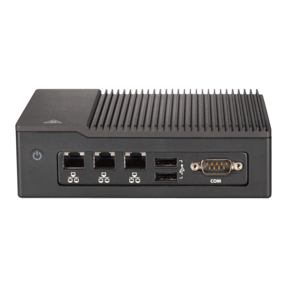
SuperServer E50-9AP-N5 User's Manual Front I/O The illustration below shows the features included on the rear of the system. Figure 1-2. Rear I/O Rear I/O Features Item Features Description Power Button Applies or removes power from the system. LAN Port GbE LAN Port USB 3.0 Ports... -
Page 11: Motherboard Layout
Chapter 1: Introduction 1.4 Motherboard Layout Below is a layout of the A2SAP-H with jumper, connector, and LED locations shown. See the table on the following page for descriptions. For detailed descriptions, pinout information, and jumper settings, refer to Chapter 3. JLAN2 JHDMI1 JLAN1... -
Page 12: Quick Reference Table
SuperServer E50-9AP-N5 User's Manual Quick Reference Table Jumper Description Jumper Setting Pins 2-4 (Force Power On) Force Power On Pins 4-6 (Power Button On) JLCDPWR1 Pins 1-3 (3.3V) LVDS Panel Power Source Selection Pins 3-5 (5V) Description Status Solid Green: S0 mode... -
Page 13: System Block Diagram
Chapter 1: Introduction System Block Diagram MAX. 8G SO-DIMM SUPPORTED Intel SINGLE CHANNEL DDI0 Non-ECC-SODIMM0 HDMI connector DDR3L DDR3L non ECC SKU 1866/1600/1333 MHz REALTEK High Definition PTN3460 Audio FRONT AUDIO Header LVDS Connector ALC888S-VD2-GR DP to LVDSBridge FLASH FST_SPI SPI 128Mb USB 2.0 [0] 5.0Gb/s... -
Page 14: Aom-Pico Card
SuperServer E50-9AP-N5 User's Manual 1.5 AOM-PICO Card One M.2 (M-key) connector is supported by the AOM-PICO-3L add-on module. M.2 devices are used for solid state storage and internal expansion. See Section 2.3 for the procedure to install an M.2 device. -
Page 15: Installing Mounting Brackets
Chapter 1: Introduction Installing Mounting Brackets The chassis includes mounting brackets that allow it to be mounted in any convenient space. 1. Install the brackets to the chassis with two screws in each bracket. 2. Secure the brackets to the surface where you want the system to be mounted. Figure 1-6. -
Page 16: Chapter 2 Maintenance And Component Installation
SuperServer E50-9AP-N5 User's Manual Chapter 2 Maintenance and Component Installation This chapter provides instructions on installing and replacing main system components. To prevent compatibility issues, only use components that match the specifications and/or part numbers given. Installation or replacement of most components require that power first be removed from the system. -
Page 17: Motherboard Components
The E50-9AP-N5 features an embedded Intel® Atom x5-E3940 processor. Memory Support The A2SAP-H supports up to 8GB of DDR3L Non-ECC SO-DIMM with speeds of up to 1866MHz in one memory slot on the top side of the motherboard. Note: Check the Supermicro website for recommended memory modules. -
Page 18: Installing Memory
SuperServer E50-9AP-N5 User's Manual Installing Memory Caution: Exercise extreme care when installing or removing DIMM modules to prevent damage. Figure 2-2. Installing a DIMM... - Page 19 Chapter 2: Maintenance and Component Installation SO-DIMM Installation 1. Power down the system as described in Section 2.1 and remove the cover as described in Section 2.2 2. Position the SODIMM module's bottom key so it aligns with the receptive point on the slot.
-
Page 20: Solid State Drive
SuperServer E50-9AP-N5 User's Manual Solid State Drive The E50-9AP-N5 supports one 2.5" SSD 7-mm in height. Figure 2-3. Installing an Solid State Drive (SSD) Installation 1. Power down the system as described in Section 2.1 and remove the cover as described in Section 2.2... -
Page 21: E-Key 2230 And Mini Pci-E
Chapter 2: Maintenance and Component Installation M.2 E-key 2230 and Mini PCI-E The E50-9AP-N5 supports one M.2-key 2230 and one full-size Mini PCI-E. Figure 2-4. M.2 B-Key 2242 and Half-size Mini PCI-E Installation 1. Power down the system as described in Section 2.1 and remove the cover as described in Section 2.2 2. -
Page 22: Chapter 3 Motherboard Connections
SuperServer E50-9AP-N5 User's Manual Chapter 3 Motherboard Connections This section describes the connections on the motherboard and provides pinout definitions. Depending on how the system is configured, not all connections are required. The LEDs on the motherboard are also described here. A motherboard layout indicating component locations can be found in Chapter 1. - Page 23 Chapter 3: Motherboard Connections HDMI Port The HDMI (High-Definition Multimedia Interface) ports are used to display both high definition video and digital sound through an HDMI-capable display, using the same cable. Universal Serial Bus (USB) Ports There are two USB 3.0 ports (JUSB1) on the I/O back panel. The motherboard has two additional USB 2.0 connections via the JEIO1 header.
-
Page 24: Led Indicators
SuperServer E50-9AP-N5 User's Manual 3.2 LED Indicators LAN Port LEDs There are two LAN ports (JLAN1 and JLAN2) on the I/O back panel of the motherboard. Each Ethernet LAN port has two LEDs. The green LED indicates activity, while the other Link LED may be green, amber, or off to indicate the speed of the connection. -
Page 25: Headers And Connectors
Chapter 3: Motherboard Connections 3.3 Headers and Connectors Front Panel Audio Header A 10-pin front panel audio header located on the motherboard allows you to use the onboard sound for audio playback. Connect an audio cable to the this header to use this feature. Refer to the table below for pin definitions. - Page 26 SuperServer E50-9AP-N5 User's Manual Battery Connector BT1 is a two-pin connector for an external CMOS battery. Refer to Chapter 2 for battery installation instructions. This connector is also used to clear the CMOS. To clear the CMOS, remove the battery, short pins 1-2 and then re-install the battery.
- Page 27 Chapter 3: Motherboard Connections General Purpose I/O Header The JGP1 (General Purpose Input/Output) header is an 8-bit general purpose I/O expander on a pin header via the SMBus. Refer to the table below for pin definitions. GPIO Header Pin Definition Pin# Definition Pin#...
- Page 28 SuperServer E50-9AP-N5 User's Manual JEIO1 This Supermicro I/O header provides support for the following functions: DP/HDMI, two PCIe x1, two USB 2.0, LPC, SATA, SMBus, and Power. Supermicro EI/O Pin Definition Pin# Definition Pin# Definition PCIE_EIO_RX_DP0 PCIE_EIO_TX_DP0 PCIE_EIO_RX_DN0 PCIE_EIO_TX_DN0 Functions...
- Page 29 Chapter 3: Motherboard Connections Mini PCI-E Slot The Mini PCI-E slot, located at JMP1 on the bottom side of the motherboard, is used to install a compatible Mini PCI-E device. The Mini PCI-E slot supports modules which are USB or PCI-E x1 devices, such as wireless, GNSS, and Bluetooth modules.
- Page 30 SuperServer E50-9AP-N5 User's Manual System Management Bus Header and SATA Power A System Management Bus header for additional slave devices or sensors is located at JSMBUS1 on the bottom side of the motherboard. This header also serves as a 5V SATA power box header.
- Page 31 The distance between the board-to-board stack is 11mm in height while using the male pin header (PINREX P/N:225-97-16GBEW) to stack onto the female mating connector (PINREX P/N: 620-92-16GB00). 32-Pin Connector A Connector Supermicro P/N Vendor Manufacture P/N Description CNT, PIN/HEADER, 2X16 PIN, PITCH 2MM,...
- Page 32 SuperServer E50-9AP-N5 User's Manual 34-Pin Connector B (JCOM1 + J3) A2SAP-H combines JCOM1 and J3 into a 34-pin, 2.0mm pitch pin header, including two RS- 232/422/485 connections and an audio (Mic-in/Headphone-out) connection. Refer to the table below for pin definitions and the female mating connector information. The distance between board-to-board stack is 11mm in height while using male pin header (PINREX P/N:225-97- 17GBEW) to stack onto female mating connector (PINREX P/N:620-92-17GB00).
-
Page 33: Control Panel
JF1 contains header pins for various buttons and indicators that are normally located on a control panel at the front of the chassis. These connectors are designed specifically for use with Supermicro chassis. Refer to the figure below for the descriptions of the front control panel buttons and LED indicators. - Page 34 SuperServer E50-9AP-N5 User's Manual Reset Button The Reset Button connection is located on pins 3 and 4 of JF1. Attach it to a hardware reset switch on the computer case to reset the system. Refer to the table below for pin definitions.
-
Page 35: Jumper Settings
Chapter 3: Motherboard Connections 3.4 Jumper Settings How Jumpers Work To modify the operation of the motherboard, jumpers can be used to choose between optional settings. Jumpers create shorts between two pins to change the function of the connector. Pin 1 is identified with a square solder pad on the printed circuit board. See the diagram below for an example of jumping pins 1 and 2. -
Page 36: Chapter 4 Software Installation
The Supermicro website contains drivers and utilities for your system at https://www. supermicro.com/wdl/driver. Some of these must be installed, such as the chipset driver. After accessing the website, go into the CDR_Images (in the parent directory of the above link) and locate the ISO file for your motherboard. Download this file to create a DVD of the drivers and utilities it contains. -
Page 37: Superdoctor ® 5
The bottom icon with a CD on it allows you to view the entire contents. 4.2 SuperDoctor ® The Supermicro SuperDoctor 5 is a hardware monitoring program that functions in a command-line or web-based interface in Windows and Linux operating systems. The program monitors system health information such as CPU temperature, system voltages, system power consumption, fan speed, and provides alerts via email or Simple Network Management Protocol (SNMP). -
Page 38: Chapter 5 Bios
SuperServer E50-9AP-N5 User's Manual Chapter 5 BIOS 5.1 Introduction This chapter describes the AMI BIOS setup utility for the A2SAP-H motherboard. It also provides the instructions on how to navigate the AMI BIOS setup utility screens. The AMI ROM BIOS is stored in a Flash EEPROM and can be easily updated. -
Page 39: Main Page
The date must be entered in Day MM/DD/YYYY format. The time is entered in HH:MM:SS format. Note: The time is in the 24-hour format. For example, 5:30 P.M. appears as 17:30:00. Supermicro A2SAP-H BIOS Version; Build Date Memory Information: Total Memory; Memory Speed... -
Page 40: Advanced Page
SuperServer E50-9AP-N5 User's Manual 5.3 Advanced Page Use this tab page to set some boot, power, CPU, SATA, server ME, and input/output settings. Caution: Take caution when changing the Advanced settings. An incorrect value, a very high DRAM frequency, or an incorrect DRAM timing setting might make the system unstable. When this occurs, revert to the manufacture default settings. - Page 41 Chapter 5: BIOS Wait For "F1" If Error This feature forces the system to wait until the F1 key is pressed if an error occurs. The options are Disabled and Enabled. INT19 Trap Response Interrupt 19 is the software interrupt that handles the boot disk function. When this item is set to Immediate, the ROM BIOS of the host adaptors will "capture"...
- Page 42 SuperServer E50-9AP-N5 User's Manual • Max CPU Speed • Min CPU Speed • Processor Cores • Intel HT Technology • Intel VT-x Technology • L1 Data Cache • L1 Code Cache • L2 Cache • L3 Cache • Speed •...
- Page 43 Chapter 5: BIOS Power Limit 1 Power Use this item to configure the value for Power Limit 1. The value is in milli watts and the step size is 125mW. Use the number keys on your keyboard to enter the value. Enter Auto to use the manufacture default setting.
- Page 44 SuperServer E50-9AP-N5 User's Manual Chipset Warning: Setting the wrong values in the following sections may cause the system to malfunc- tion. North Bridge Memory Information Memory Slot0 - 8192 MB (LPDDR3) Max TOLUD This feature sets the maximum TOLUD value, which specifies the "Top of Low Usable DRAM"...
- Page 45 Chapter 5: BIOS GTT Size Use this feature to set the memory size to be used by the graphics translation table (GTT). The options are 2MB, 4MB, and 8MB. Aperture Size Use this feature to set the Aperture size, which is the size of system memory reserved by the BIOS for graphics device use.
- Page 46 SuperServer E50-9AP-N5 User's Manual system configuration. Select Disabled to disable ASPM support. The options are Disable, L0s, L1, L0sL1, and Auto. PCIe Speed Uses this feature to select the PCI speed for the device installed in the slot. The options are Auto, Gen1, and Gen2.
- Page 47 Chapter 5: BIOS PCIe Speed Use this feature to select the PCI speed for the device installed in the slot. The options are Auto, Gen1, and Gen2. Mini PCIe ASPM Use this item to set the Active State Power Management (ASPM) level for a PCI-E de- vice.
- Page 48 SuperServer E50-9AP-N5 User's Manual SATA Mode Selection Use this item to select the mode for the installed SATA drives. The options are AHCI and RAID. Aggressive LPM (Link Power Management) Support When this item is set to Enabled, the SATA AHCI controller manages the power usage of the SATA link.
- Page 49 Chapter 5: BIOS Spin Up Device When the value of an edge detect or the value of an image binary (pixel) of a device is from 0 to 1, select Enabled to allow the PCH to start a COMRESET initialization sequence on this device.
- Page 50 SuperServer E50-9AP-N5 User's Manual Device Settings This item displays the base I/O port address and the Interrupt Request address of a serial port specified by the user. Change Settings This feature specifies the base I/O port address and the Interrupt Request address of Serial Port 1.
- Page 51 Chapter 5: BIOS • VCORE • VDIMM • 3VCC • 3VSB • VBAT • AVSB Serial Port Console Redirection COM1 Console Redirection Select Enabled to enable console redirection support for a serial port specified by the user. The options are Enabled and Disabled. *If the item above set to Enabled, the following items will become available for configuration: COM1 Console Redirection Settings...
- Page 52 SuperServer E50-9AP-N5 User's Manual the parity bit is set to 0, and the number of 1's in data bits is odd. Select None if you do not want to send a parity bit with your data bits in transmission. Select Mark to add a mark as a parity bit to be sent along with the data bits.
- Page 53 Chapter 5: BIOS *If the item above set to Enabled, the following items will become available for configuration: COM2 Console Redirection Settings Use this feature to specify how the host computer will exchange data with the client computer, which is the remote computer used by the user. The options are Enabled and Disabled.
- Page 54 SuperServer E50-9AP-N5 User's Manual COM2 VT-UTF8 Combo Key Support Select Enabled to enable VT-UTF8 Combination Key support for ANSI/VT100 terminals. The options are Disabled and Enabled. COM2 Recorder Mode Select Enabled to capture the data displayed on a terminal and send it as text messages to a remote server.
- Page 55 Chapter 5: BIOS Bits Per Second This item sets the transmission speed for a serial port used in Console Redirection. Make sure that the same speed is used in the host computer and the client computer. A lower transmission speed may be required for long and busy lines. The options are 9600, 19200, 57600, and 115200 (bits per second).
- Page 56 SuperServer E50-9AP-N5 User's Manual Network Stack Select Enabled to enable PXE (Preboot Execution Environment) or UEFI (Unified Extensible Firmware Interface) for network stack support. The options are Disabled and Enabled. *If Network Stack is Enabled, the following four items will become available for...
- Page 57 Chapter 5: BIOS Link Speed This feature allows the user to specify the port speed used for the selected boot protocol. The options are Auto Negotiated, 10 Mbps Half, 10 Mbps Full, 100 Mbps Half, and 100 Mbps Full. Wake On LAN Select Enabled for Wake On LAN support, which will allow the system to wake up when an onboard device receives an incoming signal.
- Page 58 SuperServer E50-9AP-N5 User's Manual Intel® I210 Gigabit Network Connection - 00:25:90:5E:CE:37 NIC Configuration Link Speed This feature allows the user to specify the port speed used for the selected boot protocol. The options are Auto Negotiated, 10 Mbps Half, 10 Mbps Full, 100 Mbps Half, and 100 Mbps Full.
-
Page 59: Security
Chapter 5: BIOS Virtual MAC Address This item displays the Virtual MAC address for this computer. MAC addresses are six two- digit hexadecimal numbers. 5.4 Security This menu allows the user to configure Security settings. Password Check Use this feature to determine when a password entry is required. Select Setup to require the password only when entering setup. - Page 60 SuperServer E50-9AP-N5 User's Manual Secure Boot Secure Boot Support Select Enable for secure boot support to ensure system security at bootup. The options are Enabled and Disabled. Secure Boot Mode This feature allows the user to select the desired secure boot mode for the system. The options are Standard and Customized.
- Page 61 Chapter 5: BIOS Key Exchange Keys (KEK) Set New Var Select Yes to load the KEK from the manufacturer's defaults. Select No to load the KEK from a file. The options are Yes and No. Append Key Select Yes to add the KEK from the manufacturer's defaults list to the existing KEK. Select No to load the KEK from a file.
- Page 62 SuperServer E50-9AP-N5 User's Manual OsRecovery Signature This item uploads and installs an OSRecovery Signature. You may insert a factory default key or load from a file. The file formats accepted are: 1) Public Key Certificate a. EFI Signature List b.
-
Page 63: Boot
Chapter 5: BIOS 5.5 Boot Use this tab page to manage security settings. Boot mode select Use this feature to select the boot mode. The options are LEGACY, UEFI, and DUAL. Fixed Boot Order Priorities This option prioritizes the order of bootable devices that the system can boot from. Press <Enter>... - Page 64 SuperServer E50-9AP-N5 User's Manual • Boot Option #8 • Boot Option #9 UEFI Application Boot Priorities This feature allows the user to specify which UEFI devices are boot devices. • UEFI Boot Option #1 UEFI NETWORK Drive BBS Priorities This feature allows the user to specify which UEFI network drive devices are boot devices.
-
Page 65: Save & Exit
Chapter 5: BIOS 5.6 Save & Exit Select the Exit tab from the BIOS setup utility screen to enter the Exit BIOS Setup screen. Save Options Discard Changes and Exit Select this option to quit the BIOS Setup without making any permanent changes to the system configuration, and reboot the computer. - Page 66 SuperServer E50-9AP-N5 User's Manual Default Options Restore Defaults To set this feature, select Restore Defaults from the Exit menu and press <Enter>. These are factory settings designed for maximum system performance but not for maximum stability. Save as User Defaults To set this feature, select Save as User Defaults from the Exit menu and press <Enter>.
-
Page 67: Appendix A Bios Error Codes
When BIOS performs the Power-On Self-Test, it writes checkpoint codes to I/O port 0080h. If the computer cannot complete the boot process, a diagnostic card can be attached to the computer to read I/O port 0080h (Supermicro p/n AOC-LPC80-20). For information on AMI updates, please refer to http://www.ami.com/products/. -
Page 68: Appendix B Standardized Warning Statements For Dc Systems
Supermicro's Technical Support department for assistance. Only certified technicians should attempt to install or configure components. Read this appendix in its entirety before installing or configuring components in the Supermicro chassis. These warnings may also be found on our website at http://www.supermicro.com/about/... - Page 69 Appendix B: Standardized Warning Statements Warnung WICHTIGE SICHERHEITSHINWEISE Dieses Warnsymbol bedeutet Gefahr. Sie befinden sich in einer Situation, die zu Verletzungen führen kann. Machen Sie sich vor der Arbeit mit Geräten mit den Gefahren elektrischer Schaltungen und den üblichen Verfahren zur Vorbeugung vor Unfällen vertraut. Suchen Sie mit der am Ende jeder Warnung angegebenen Anweisungsnummer nach der jeweiligen Übersetzung in den übersetzten Sicherheitshinweisen, die zusammen mit diesem Gerät ausgeliefert wurden.
- Page 70 SuperServer E50-9AP-N5 User's Manual . ٌ ا ك ً ف حالة و ٌ يك أى تتسبب ف اصابة جسذ ة ٌ هذا الزهز ع ٌ خطز !تحذ ز قبل أى تعول عىل أي هعذات،يك عىل علن بالوخاطز ال ا ٌجوة عي الذوائز...
- Page 71 Appendix B: Standardized Warning Statements Warnung Vor dem Anschließen des Systems an die Stromquelle die Installationsanweisungen lesen. ¡Advertencia! Lea las instrucciones de instalación antes de conectar el sistema a la red de alimentación. Attention Avant de brancher le système sur la source d'alimentation, consulter les directives d'installation. .יש...
- Page 72 SuperServer E50-9AP-N5 User's Manual Warnung Dieses Produkt ist darauf angewiesen, dass im Gebäude ein Kurzschluss- bzw. Überstromschutz installiert ist. Stellen Sie sicher, dass der Nennwert der Schutzvorrichtung nicht mehr als: 12VDC, 3A beträgt. ¡Advertencia! Este equipo utiliza el sistema de protección contra cortocircuitos (o sobrecorrientes) del edificio.
- Page 73 Appendix B: Standardized Warning Statements Power Disconnection Warning Warning! The system must be disconnected from all sources of power and the power cord removed from the power supply module(s) before accessing the chassis interior to install or remove system components. 電源切断の警告...
- Page 74 SuperServer E50-9AP-N5 User's Manual يجب فصم اننظاو من جميع مصادر انطاقت وإ ز انت سهك انكهرباء من وحدة امداد انطاقت قبم انىصىل إىن امنناطق انداخهيت نههيكم نتثبيج أو إ ز انت مكىناث الجهاز 경고! 시스템에 부품들을 장착하거나 제거하기 위해서는 섀시 내부에 접근하기 전에 반드시 전원...
- Page 75 Appendix B: Standardized Warning Statements Attention Il est vivement recommandé de confier l'installation, le remplacement et la maintenance de ces équipements à des personnels qualifiés et expérimentés. !אזהרה .צוות מוסמך בלבד רשאי להתקין, להחליף את הציוד או לתת שירות עבור הציוד واملدربيه...
- Page 76 SuperServer E50-9AP-N5 User's Manual Warnung Diese Einheit ist zur Installation in Bereichen mit beschränktem Zutritt vorgesehen. Der Zutritt zu derartigen Bereichen ist nur mit einem Spezialwerkzeug, Schloss und Schlüssel oder einer sonstigen Sicherheitsvorkehrung möglich. ¡Advertencia! Esta unidad ha sido diseñada para instalación en áreas de acceso restringido. Sólo puede obtenerse acceso a una de estas áreas mediante la utilización de una herramienta especial,...
- Page 77 Appendix B: Standardized Warning Statements Battery Handling Warning! There is the danger of explosion if the battery is replaced incorrectly. Replace the battery only with the same or equivalent type recommended by the manufacturer. Dispose of used batteries according to the manufacturer's instructions 電池の取り扱い...
- Page 78 SuperServer E50-9AP-N5 User's Manual هناك خطر من انفجار يف حالة اسحبذال البطارية بطريقة غري صحيحة فعليل اسحبذال البطارية فقط بنفس النىع أو ما يعادلها مام أوصث به الرشمة املصنعة جخلص من البطاريات املسحعملة وفقا لحعليامت الرشمة الصانعة 경고! 배터리가 올바르게 교체되지 않으면 폭발의 위험이 있습니다. 기존 배터리와 동일하거나 제...
- Page 79 Appendix B: Standardized Warning Statements Comply with Local and National Electrical Codes Warning! Installation of the equipment must comply with local and national electrical codes. 地方および国の電気規格に準拠 機器の取り付けはその地方および国の電気規格に準拠する必要があります。 警告 设备安装必须符合本地与本国电气法规。 警告 設備安裝必須符合本地與本國電氣法規。 Warnung Die Installation der Geräte muss den Sicherheitsstandards entsprechen. ¡Advertencia! La instalacion del equipo debe cumplir con las normas de electricidad locales y nacionales.
- Page 80 SuperServer E50-9AP-N5 User's Manual Product Disposal Warning! Ultimate disposal of this product should be handled according to all national laws and regulations. 製品の廃棄 この製品を廃棄処分する場合、 国の関係する全ての法律 ・ 条例に従い処理する必要があります。 警告 本产品的废弃处理应根据所有国家的法律和规章进行。 警告 本產品的廢棄處理應根據所有國家的法律和規章進行。 Warnung Die Entsorgung dieses Produkts sollte gemäß allen Bestimmungen und Gesetzen des Landes erfolgen.
- Page 81 Appendix B: Standardized Warning Statements Waarschuwing De uiteindelijke verwijdering van dit product dient te geschieden in overeenstemming met alle nationale wetten en reglementen. DC Power Supply Warning! When stranded wiring is required, use approved wiring terminations, such as closedloop or spade-type with upturned lugs. These terminations should be the appropriate size for the wires and should clamp both the insulation and conductor.
- Page 82 SuperServer E50-9AP-N5 User's Manual وأ ةقلغم ةقلح لثم ،اهيلع ةقفاوملا ءاهنإ كالسألا مادختساو ،لبسلا مهب تعطقت نيذلا كالسألا ابولطم نوكي امدنع بجيو كالسألل بسانملا مجحلا نوكي تاءاهنإلا هذهل يغبنيو .ةبولقم تاورعلا عم عونلا ةيقيقحلا اهئامسأب ءايشألا .لصومو لزعلا نم لك حبك...
- Page 83 Appendix B: Standardized Warning Statements Warnung Vor Ausführung der folgenden Vorgänge ist sicherzustellen, daß die Gleichstromschaltung keinen Strom erhält. ¡Advertencia! Antes de proceder con los siguientes pasos, comprobar que la alimentación del circuito de corriente continua (CC) esté cortada (OFF). Attention Avant de pratiquer l'une quelconque des procédures ci-dessous, vérifier que le circuit en courant continu n'est plus sous tension.
- Page 84 SuperServer E50-9AP-N5 User's Manual Hazardous Voltage or Energy Present on DC Power Terminals Warning! Hazardous voltage or energy may be present on DC power terminals. Always replace cover when terminals are not in service. Be sure uninsulated conductors are not accessible when cover is in place.
- Page 85 Appendix B: Standardized Warning Statements امدنع امئاد ءاطغ لادبتسا .ةمصاعلا ةقاطلا تاطحم ىلع ةدوجوم نوكت ةقاطلا وأ ةرطخلا دهجلا دق ءاطغلا امدنع اهيلإ لوصولا نكمي ال لوزعم ريغ تالصوملا هيف كش ال امم .ةمدخلا يف تسيل تاطحملا .هناكم يف 주의! DC전원...
-
Page 86: Appendix C System Specifications
SuperServer E50-9AP-N5 User's Manual Appendix C System Specifications Processors Single Intel® Atom x5-E3940 (System on Chip) Note: Please refer to the motherboard specifications pages on our website for updates to supported processors. BIOS AMI® UEFI BIOS Memory Supports up to 8 GB non-ECC SODIMM; Memory Type DDR3L 1866 MHz;... - Page 87 Appendix C: System Specifications Regulatory Compliance FCC, ICES, CE, UKCA, VCCI, RCM, NRTL, CB Applied Directives, Standards EMC/EMI: 2014/30/EU (EMC Directive) Electromagnetic Compatibility Regulations 2016 FCC Part 15 Subpart B ICES-003 VCCI-CISPR 32 AS/NZS CISPR 32 BS/EN 55032 BS/EN 55035 CISPR 32 CISPR 24/CISPR 35 BS/EN 61000-3-2...
-
Page 88: Appendix D Traditional Chinese Safety Warnings
SuperServer E50-9AP-N5 User's Manual Traditional Chinese Version Appendix D Safety Warnings Traditional Chinese Safety Warnings Additional Traditional Chinese Version warning statements are included here in this appendix. 安全警告 (注意這些警告標誌) 以下的警告標誌對於安全使用本設備非常重要,可以避免操作人員遭遇危險,以及財產 受到任何損失。 錯誤使用本機器或忽視這本手冊,所引起的傷害或損失等級分類如下: Warning! (警告) 此注意標誌提醒未能依照正確指示使用機器,可能導致生 命危險 或造成嚴重傷害。 Caution ( 注意... - Page 89 Appendix D: Traditional Chinese Safety Warnings Traditional Chinese Version Safety Warnings 1. 勿使用多孔插座或延長線,否則可能造成溫度過高而引起火災。 2. 勿在電源線放置重物,否則可能引起火災或受到電擊。 3. 勿踏在電源線上,及勿損傷或任意處理電源線, 否則可能引起火災或 受到電擊。 4. 勿綁住或紮緊電源線,否則可能引起火災或受到電擊。 5. 勿將花瓶、花盆或盛水容器放在機器上,如果水滴濺出,可能引起火 災或受 到電擊 1. 機器如果產生怪味或不正常聲響,必需立即關閉機器電源開關,然後 從插座 取下插頭 2. 絕對不可以沾濕的手插拔插頭,否則可能受到電擊。 3. 插頭必須確實插妥在插座上,如果未能妥善插好,可能會引起火災。 4. 僅可使用機器所附電源插頭。 拔取電源線時,確實抓住插頭部位,否則導致插頭破裂可能引起火 災或受到電 擊。 不可企圖拆解或擅自修改機器,否則可能引起火災或受到電擊。 不可將機器安裝在下列場所: 1.
- Page 90 SuperServer E50-9AP-N5 User's Manual 限 限 用 用 物 物 質 質 含 含 有 有 情 情 況 況 標 標 示 示 聲 聲 明 明 書 書 Declaration of the Presence Condition of the Restricted Substances Marking 設備名稱:嵌入式系統/ Embedded System...
-
Page 91: Appendix E Uefi Bios Recovery
Warning: Do not upgrade the BIOS unless your system has a BIOS-related issue. Flashing the wrong BIOS can cause irreparable damage to the system. In no event shall Supermicro be liable for direct, indirect, special, incidental, or consequential damages arising from a BIOS update. - Page 92 SuperServer E50-9AP-N5 User's Manual The file system supported by UEFI is FAT (including FAT12, FAT16, and FAT32) which is installed on a bootable or non-bootable USB-attached device. However, the BIOS might need several minutes to locate the SUPER.ROM file if the media size becomes too large due to the huge volumes of folders and files stored in the device.
- Page 93 Appendix E: UEFI BIOS Recovery 4. After locating the new BIOS binary image, the system will enter the BIOS Recovery menu as shown below. Note: At this point, you may decide if you want to start the BIOS recovery. If you decide to proceed with BIOS recovery, follow the procedures below.
- Page 94 SuperServer E50-9AP-N5 User's Manual Note: Do not interrupt the BIOS flashing process until it has completed. 6. After the BIOS recovery process is completed, press any key to reboot the system. 7. Using a different system, extract the BIOS package into a USB flash drive.
- Page 95 Appendix E: UEFI BIOS Recovery 9. When the UEFI Shell prompt appears, type fs# to change the device directory path. Go to the directory that contains the BIOS package you extracted earlier from Step 7. Enter flash.nsh BIOSname.### at the prompt to start the BIOS update process. Note: Do not interrupt this process until the BIOS flashing is complete.
Need help?
Do you have a question about the SuperServer E50-9AP-N5 and is the answer not in the manual?
Questions and answers