Table of Contents
Advertisement
Advertisement
Table of Contents

Related Manuals for Supermicro SuperServer E300-9D


Summary of Contents for Supermicro SuperServer E300-9D
- Page 1 ® UpER ERvER E300-9D USER’S MANUAL Revision 1.0...
- Page 2 State of California, USA. The State of California, County of Santa Clara shall be the exclusive venue for the resolution of any such disputes. Supermicro's total liability for all claims will not exceed the price paid for the hardware product.
- Page 3 Preface About this Manual This manual is written for professional system integrators and PC technicians. It provides information for the installation and use of the SuperServer E300-9D. Installation and maintenance should be performed by experienced technicians only. Notes For your system to work properly, please follow the links below to download all necessary drivers/utilities and the user’s manual for your server.
-
Page 4: Table Of Contents
SuperServer E300-9D User's Manual Contents Chapter 1 Introduction 1.1 Overview ..........................7 1.2 System Features ........................8 1.3 Chassis Features .........................9 Front Features ........................9 Rear Features ........................10 1.4 Motherboard Layout ......................11 Quick Reference Table ......................12 Chipset Block Diagram......................13 1-5 Server Installation and Setup .....................14 Unpacking the System ......................14... - Page 5 Preface 3.4 Jumpers ..........................33 Explanation of Jumpers.....................33 3.5 LED Indicators ........................35 3.6 SATA Connections ......................38 Chapter 4 Software 4.1 Driver Installation ........................39 4.2 SuperDoctor 5 ........................40 ® 4.3 IPMI ............................41 Chapter 5 BIOS 5.1 Introduction .........................42 Starting the Setup Utility ....................42 5.2 Main Setup .........................43 5.3 Advanced ..........................45 5.4 Event Logs .........................71...
- Page 6 SuperServer E300-9D User's Manual Contacting Supermicro Headquarters Address: Super Micro Computer, Inc. 980 Rock Ave. San Jose, CA 95131 U.S.A. Tel: +1 (408) 503-8000 Fax: +1 (408) 503-8008 Email: marketing@supermicro.com (General Information) support@supermicro.com (Technical Support) Website: www.supermicro.com Europe Address: Super Micro Computer B.V.
-
Page 7: Chapter 1 Introduction
Introduction 1.1 Overview The SuperServer E300-9D is a compact, embedded system comprised of the SCE300 chassis and the X11SDV-4C-TLN2F single processor motherboard. Refer to our website for information on operating systems that have been certified for use with the system (www. -
Page 8: System Features
SuperServer E300-9D User's Manual 1.2 System Features The following table provides an overview of the main features of the E300-9D. Please refer to Appendix C for additional specifications. System Features Motherboard X11SDV-4C-TLN2F Chassis Compact Embedded Mini ITX Box, SCE300 Intel Xeon D-2123IT (System on a Chip) Memory Four DDR4 DIMM sockets;... -
Page 9: Chassis Features
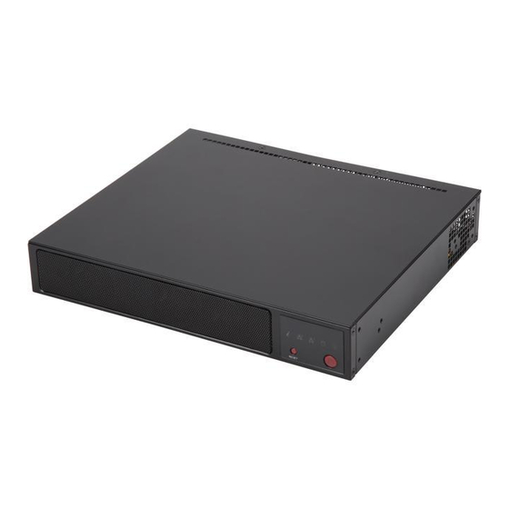
Chapter 1: Introduction 1.3 Chassis Features The SCE300 is a compact embedded 1U chassis for Mini ITX and a Flex ATX motherboard. Front Features The front of the chassis includes the control panel. Figure 1-1. Chassis Front and Control Panel Control Panel Features Item Features... -
Page 10: Rear Features
SuperServer E300-9D User's Manual Information LED Status Description Continuously on and An overheat condition has occurred. (This may be caused by cable congestion.) Blinking red (1Hz) Fan failure, check for an inoperative fan. Power failure, check for a non-operational power Blinking red (0.25Hz) -
Page 11: Motherboard Layout
Chapter 1: Introduction 1.4 Motherboard Layout Below is a layout of the X11SDV-4C-TLN2F with jumper, connector and LED locations shown. See the table on the following page for descriptions. For detailed descriptions, pin-out information and jumper settings, refer to Chapter 4. LED2 JUIDB1 LED3... -
Page 12: Quick Reference Table
SuperServer E300-9D User's Manual Quick Reference Table Jumper Description Default Setting JBT1 CMOS Clear Open: Normal, Closed: Clear CMOS C1, JI SMB to PCI-E Slots Enable/Disable Pins 2-3 (Disabled) JNS1 OCuLink to 4x SATA or PCI-E x4 Selection Pins 2-3: (PCI-E x4) -
Page 13: Chipset Block Diagram
Chapter 1: Introduction Chipset Block Diagram DDR4 1866/2133/2400/2666 DDR4 1866/2133/2400/2666 PCIE 3.0 x8 JPCIE2 SLOT7 PCIE 3.0 x8 PE1[7:0] PE1[15:8] JLAN1 10G PHY X557-AT2 SATA3.0#3 SATA3.0#2 SATA3.0 Flexible I/O FLASH 15~12 SATA3.0#1 SATA3.0#0 USB 3.0/2.0 Flexible I/O USB 3.0 Rear I/O x2 Flexible I/O PCIE3.0 or SATA3.0 x4 OCuLink... -
Page 14: Server Installation And Setup
SuperServer E300-9D User's Manual 1-5 Server Installation and Setup The server is shipped with the onboard processor and the motherboard installed in the chassis. Several steps are necessary to begin using your server. You must add memory, mount the hard disk drive, and mount the system in place. -
Page 15: Installing Rack Mounting Brackets
Chapter 1: Introduction Installing Rack Mounting Brackets The chassis can be mounted in a rack using two rack brackets and a two-part power adapter shelf bracket (optional, MCP-290-30002-0B). 1. Attach the rack brackets using three screws through the holes in each bracket to secure the bracket to the chassis. -
Page 16: Chapter 2 Maintenance And Component Installation
SuperServer E300-9D User's Manual Chapter 2 Maintenance and Component Installation This chapter provides instructions on installing and replacing main system components. To prevent compatibility issues, only use components that match the specifications and/or part numbers given. Installation or replacement of most components require that power first be removed from the system. -
Page 17: Accessing The System
Chapter 2 Maintenance and Component Installation 2.2 Accessing the System The SCE300 features a removable top cover to access to the inside of the chassis. Figure 2-1. Removing the Chassis Cover Removing the Top Cover 1. Power down the system as described in section 2.1. 2. -
Page 18: Motherboard Components
Populating these DIMM slots with memory modules of the same type and size will result in interleaved memory, which will improve memory performance. Note: Check the Supermicro website for recommended memory modules. Memory Population Sequence When installing memory modules, the DIMM slots should be populated in the following order: DIMMA1, DIMMB1, DIMMD1, DIMME1. -
Page 19: Installing Memory
Chapter 2 Maintenance and Component Installation Installing Memory When installing memory modules, the DIMM slots should be populated in the following order: DIMMA1, DIMMB1, then DIMMA2, DIMMB2. • Always use DDR4 DIMM modules of the same size, type and speed. Mixing memory modules of different types and speeds is not allowed. -
Page 20: Solid State Storage
SuperServer E300-9D User's Manual Solid State Storage This motherboard supports four internally mounted solid state storage cards: • Four SATA 3.0 ports(SATA/SAS HDD/SSD). Up to eight SATA 3.0 ports (four via OCuLink connection). • One OCuLink port can be utilized as four SATA ports or a single U.2 NVMe port. -
Page 21: Motherboard Battery
Chapter 2 Maintenance and Component Installation Motherboard Battery The motherboard uses non-volatile memory to retain system information when system power is removed. This memory is powered by a lithium battery residing on the motherboard. Figure 2-3. Installing the Onboard Battery Replacing the Battery 1. -
Page 22: Chassis Components
SuperServer E300-9D User's Manual 2.4 Chassis Components Installing the Storage Drive The SCE300 can accommodate a single fixed 2.5" storage drive of 9.5 mm thickness. It is installed to a mounting tray inside the chassis. Use an enterprise quality drive. -
Page 23: Installing The Riser Card
Chapter 2 Maintenance and Component Installation 4. Return the drive tray assembly into the chassis, aligning the tabs of the tray with the slots in the chassis. Secure the tray to the chassis support bracket with the screws previously set aside. 5. -
Page 24: System Cooling
SuperServer E300-9D User's Manual System Cooling The SCE300 includes two replaceable 4-cm fans. An optional third fan can be purchased. Replacing the System Fan 1. Power down the system as described in section 2.1 and remove the AC power cord and the chassis cover. -
Page 25: Chapter 3 Motherboard Connections
Chapter 3 Motherboard Connections Chapter 3 Motherboard Connections This section describes the connections on the X11SDV-4C-TLN2F motherboard and provides pinout definitions. Note that depending on how the system is configured, not all connections are required. The LEDs on the motherboard are also described here. A motherboard layout indicating component locations may be found in Chapter 1. -
Page 26: Headers And Connectors
SuperServer E300-9D User's Manual 3.2 Headers and Connectors Fan Headers The X11SDV-4C-TLN2F has three 4-pin fan headers (FAN1, FAN2, FANA). These headers are backwards-compatible with the traditional 3-pin fans. However, fan speed control is available for 4-pin fans only by Thermal Management via the IPMI 2.0 interface. Refer to the table below for pin definitions. - Page 27 Chapter 3 Motherboard Connections OCuLink Connector The X11SDV-4C-TLN2F includes an OCuLink connector, which can be used either for high- performance storage connectivity via the NVMe interface or for additional SATA storage. Depending on the setting of jumper JNS1, this OCuLink connector (P1NVMe0) can be utilized as four SATA ports or as a single U.2 NVMe port.
- Page 28 SuperServer E300-9D User's Manual TPM/Port 80 Header A Trusted Platform Module (TPM)/Port 80 header is located at JTPM1 to provide TPM support and a Port 80 connection. Use this header to enhance system performance and data security. Refer to the table below for pin definitions.
-
Page 29: Control Panel
Chapter 3 Motherboard Connections Control Panel JF1 contains header pins for various control panel connections. See the figure below for the pin locations and definitions of the control panel buttons and LED indicators. All JF1 wires have been bundled into a single cable to simplify this connection. Make sure the red wire plugs into pin 1 as marked on the motherboard. - Page 30 SuperServer E300-9D User's Manual Power Fail LED The Power Fail LED connection is located on pins 5 and 6 of JF1. Power Fail LED Pin Definitions (JF1) Pin# Definition 3.3V PWR Supply Fail Overheat (OH)/Fan Fail/PWR Fail LED Connect an LED cable to pins 7 and 8 of the Front Control Panel to use the Overheat (OH)/ Fan Fail/PWR Fail LED connections.
-
Page 31: Ports
Chapter 3 Motherboard Connections HDD LED The HDD LED connection is located on pins 13 and 14 of JF1. Attach a cable to show the hard drive activity status. Refer to the table below for pin definitions. HDD LED Pin Definitions (JF1) Pin# Definition 3.3V Stdby... - Page 32 SuperServer E300-9D User's Manual VGA Port A VGA video port is located on the I/O back panel. Use this connection for a VGA display. LAN Ports There are two LAN ports located on the I/O back panel of the motherboard. LAN1 and LAN2 are 10GbE RJ45 Ethernet ports.
-
Page 33: Jumpers
Chapter 3 Motherboard Connections 3.4 Jumpers Explanation of Jumpers To modify the operation of the motherboard, jumpers are used to choose between optional settings. Jumpers create shorts between two pins to change the function associated with it. Pin 1 is identified with a square solder pad on the printed circuit board. See the motherboard layout page for jumper locations. - Page 34 SuperServer E300-9D User's Manual SMBus to PCI-E Slots Use jumpers JI C1 and JI C2 to enable PCI-E SMB (System Management Bus) support to improve system management for the onboard PCI-E slot. SMBus to PCI-E Slots Jumper Settings Jumper Setting...
-
Page 35: Led Indicators
Chapter 3 Motherboard Connections Watch Dog JWD1 controls the Watch Dog function. Watch Dog is a monitor that can reboot the system when a software application hangs. Jumping pins 1-2 will cause Watch Dog to reset the system if an application hangs. Jumping pins 2-3 will generate a non-maskable interrupt signal for the application that hangs. - Page 36 SuperServer E300-9D User's Manual Power LED LED1 is an Onboard Power LED. When this LED is lit, it means power is present on the motherboard. In suspend mode, this LED will blink on and off. Be sure to turn off the system and unplug the power cord(s) before removing or installing components.
- Page 37 Chapter 3 Motherboard Connections Main Power LED A Main Power LED is located at LED3 on the motherboard. When this LED is on, the system power is on. Be sure to turn off the system power and unplug the power cord before removing or installing components.
-
Page 38: Sata Connections
SATA Ports (S-SATA0 - S-SATA3) There are four SATA 3.0 ports on the motherboard. These ports provide serial-link signal connections with the option of Intel RSTe [RAID 0,1,5,10]. S-SATA1 also supports SuperDOM, Supermicro's proprietary SATA DOM with a built-in power connection via pin 8. -
Page 39: Chapter 4 Software
This section describes the installation of drivers and management programs for the system. 4.1 Driver Installation The Supermicro FTP site contains drivers and utilities for your system at ftp://ftp.supermicro. com. Some of these must be installed, such as the chipset driver. -
Page 40: Superdoctor ® 5
4.2 SuperDoctor ® The Supermicro SuperDoctor 5 is a program that functions in a command-line or web-based interface for Windows and Linux operating systems. The program monitors such system health information as CPU temperature, system voltages, system power consumption, fan speed, and provides alerts via email or Simple Network Management Protocol (SNMP). -
Page 41: Ipmi
The X11SDV-4C-TLN2F supports the Intelligent Platform Management Interface (IPMI) v2.0. IPMI is used to provide remote access, monitoring and management. There are several BIOS settings that are related to IPMI. For general documentation and information on IPMI, please visit our website at: http://www.supermicro.com/products/nfo/IPMI.cfm. -
Page 42: Chapter 5 Bios
SuperServer E300-9D User's Manual Chapter 5 BIOS 5.1 Introduction This chapter describes the AMIBIOS™ Setup utility for the X11SDV-4C-TLN2F motherboard. The BIOS is stored on a chip and can be easily upgraded using a flash program. Note: Due to periodic changes to the BIOS, some settings may have been added or deleted and might not yet be recorded in this manual. -
Page 43: Main Setup
Note: The time is in the 24-hour format. For example, 5:30 P.M. appears as 17:30:00. The date's default value is the BIOS build date after RTC reset. Supermicro X11SDV-4C-TLN2F BIOS Version This feature displays the version of the BIOS ROM used in the system. - Page 44 SuperServer E300-9D User's Manual Memory Information Total Memory This feature displays the total size of memory available in the system.
-
Page 45: Advanced
Chapter 5: BIOS 5.3 Advanced Use this menu to configure advanced settings. Warning: Take caution when changing the Advanced settings. An incorrect value, a very high DRAM frequency or an incorrect BIOS timing setting may cause the system to malfunction. When this occurs, restore to default manufacturer settings. - Page 46 SuperServer E300-9D User's Manual INT19 Trap Response Interrupt 19 is the software interrupt that handles the boot disk function. When this feature is set to Immediate, the ROM BIOS of the host adaptors will "capture" Interrupt 19 at bootup immediately and allow the drives that are attached to these host adaptors to function as bootable disks.
- Page 47 Chapter 5: BIOS • Processor Max Ratio • Processor Min Ratio • Microcode Revision • L1 Cache RAM • L2 Cache RAM • L3 Cache RAM • Processor 0 Version Hyper-Threading (ALL) Select Enabled to support Intel Hyper-threading Technology to enhance CPU performance. The options are Disable and Enable.
- Page 48 SuperServer E300-9D User's Manual Adjacent Cache Prefetch (Available when supported by the CPU) The CPU prefetches the cache line for 64 bytes if this feature is set to Disabled. The CPU prefetches both cache lines for 128 bytes as comprised if this feature is set to Enable. The options are Enable and Disable.
- Page 49 Chapter 5: BIOS *If the feature above is set to BIOS Controls EPB, the following features will be available for configuration: ENERGY_PERF_BIAS_CFG Mode The Energy Perfomance BIAS (EPB) feature allows the user to configure CPU power and perfomance settings. Select Maximum Performance to set the highest performance. Select Performance to optimize performance over energy efficiecy.
- Page 50 SuperServer E300-9D User's Manual Hardware PM State Control Hardware P-States This setting allows the user to select between OS and hardware-controlled P-states. Selecting Native Mode allows the OS to choose a P-state. Selecting Out of Band Mode allows the hardware to autonomously choose a P-state without OS guidance. Selecting Native Mode with No Legacy Support functions as Native Mode with no support for older hardware.
- Page 51 Chapter 5: BIOS Chipset Configuration Warning: Setting the wrong values in the sections below may cause the system to malfunction. North Bridge Configuration UPI Configuration The following UPI information will display: • Number of CPU • Number of IIO •...
- Page 52 SuperServer E300-9D User's Manual Sub NUMA Clustering (SNC) is a feature that breaks up the Last Level Cache (LLC) into clusters based on address range. Each cluster is connected to a subset of the memory controller. Enabling SNC improves average latency and reduces memory access conges- tion to achieve higher performance.
- Page 53 Chapter 5: BIOS Memory RAS Configuration Static Virtual Lockstep Mode Select Enable to run the system's memory channels in lockstep mode to minimize memory access latency. The options are Disable and Enable. Mirror Mode This feature allows memory to be mirrored between two channels, providing 100% redundancy.
- Page 54 SuperServer E300-9D User's Manual Patrol Scrub Patrol Scrub is a process that allows the CPU to correct correctable memory errors detected on a memory module and send the correction to the requestor (the original source). When this feature is set to Enable, the IO hub will read and write back one cache line every 16K cycles if there is no delay caused by internal processing.
- Page 55 Chapter 5: BIOS PCI-E Port Link Status This feature shows the status of the device plugged into this slot. PCI-E Port Link Max This feature shows the status of the device plugged into this slot. PCI-E Port Link Speed This feature shows the status of the device plugged into this slot. PCI-E Port Max Payload Size Use this feature to select the maximum payload size for this port.
- Page 56 SuperServer E300-9D User's Manual *If the feature above is set to Enable, the five features below will be available for configuration: Interrupt Remapping Use this feature to enable Interrupt Remapping support, which detects and controls external interrupt requests. The options are Enable and Disable.
- Page 57 Chapter 5: BIOS XHCI Hand-off This is a work-around solution for operating systems that do not support XHCI (Extensible Host Controller Interface) hand-off. The XHCI ownership change should be claimed by the XHCI driver. The settings are Enabled and Disabled. Port 60/64 Emulation Select Enabled for I/O port 60h/64h emulation support, which in turn will provide complete legacy USB keyboard support for the operating systems that do not support legacy USB...
- Page 58 SuperServer E300-9D User's Manual Aggressive Link Power Management When this feature is set to Enable, the SATA AHCI controller manages the power usage of the SATA link. The controller will put the link in a low power mode during extended periods of I/O inactivity, and will return the link to an active state when I/O activity resumes.
- Page 59 Chapter 5: BIOS sSATA Controller This feature enables or disables the onboard sSATA controller supported by the Intel PCH chip. The options are Enable and Disable. Configure sSATA as Select AHCI to configure an sSATA drive specified by the user as an AHCI drive. Select RAID to configure an sSATA drive specified by the user as a RAID drive.
- Page 60 SuperServer E300-9D User's Manual Port 0 ~ Port 5 sSATA Device Type Use this feature to specify if the SATA port specified by the user should be connected to a Solid State Drive or a Hard Disk Drive. The options are Hard Disk Drive and Solid State Drive.
- Page 61 Chapter 5: BIOS VGA Priority Use this feature to select VGA priority when multiple VGA devices are detected. Select On- board to give priority to your onboard video device. Select Offboard to give priority to your graphics card. The options are Onboard and Offboard. CPU SLOT7 PCI-E 3.0 X8 OPROM Use this feature to select which firmware type to be loaded for the add-on card in this slot.
- Page 62 SuperServer E300-9D User's Manual Ipv6 HTTP Support Select Enabled to enable IPv6 HTTP boot support. The options are Disabled and Enabled. PXE boot Wait Time Use this option to specify the wait time to press the ESC key to abort the PXE boot. Press "+"...
- Page 63 Chapter 5: BIOS Change Settings This feature specifies the base I/O port address and the Interrupt Request address of Serial Port 1. Select Auto for the BIOS to automatically assign the base I/O and IRQ address to a serial port specified. The options are Auto, (IO=2F8h; IRQ=3), (IO=3F8h; IRQ=3, 4, 5, 6, 7, 9, 10, 11, 12), (IO=2F8h;...
- Page 64 SuperServer E300-9D User's Manual Parity A parity bit can be sent along with regular data bits to detect data transmission errors. Select Even if the parity bit is set to 0, and the number of 1's in data bits is even. Select Odd if the parity bit is set to 0, and the number of 1's in data bits is odd.
- Page 65 Chapter 5: BIOS SOL Console Redirection Select Enabled to use the SOL port for Console Redirection. The options are Disabled and Enabled. *If the feature above is set to Enabled, the following features are available for configuration: Console Redirection Settings ...
- Page 66 SuperServer E300-9D User's Manual Flow Control Use this feature to set the flow control for Console Redirection to prevent data loss caused by buffer overflow. Send a "Stop" signal to stop sending data when the receiving buffer is full. Send a "Start" signal to start sending data when the receiving buffer is empty. The options are None and Hardware RTS/CTS.
- Page 67 Chapter 5: BIOS Console Redirection Select Enabled to use a COM port selected by the user for EMS Console Redirection. The options are Disabled and Enabled. *If the feature above is set to Enabled, the following features are available for configuration: Console Redirection Settings ...
- Page 68 SuperServer E300-9D User's Manual ACPI Settings Use this feature to configure Advanced Configuration and Power Interface (ACPI) power management settings for your system. WHEA Support Select Enabled to support the Windows Hardware Error Architecture (WHEA) platform and provide a common infrastructure for the system to handle hardware errors within the Windows OS environment in order to reduce system crashes and enhance system recovery and health monitoring.
- Page 69 TPM Active Status • TPM Owner Status SMCI BIOS-Based TPM Provision Support Use feature to enable the Supermicro TPM Provision support. The options are Disabled and Enabled. TXT Support Intel TXT (Trusted Execution Technology) helps protect against software-based attacks and ensures protection, confidentiality, and integrity of data stored or created on the system.
- Page 70 Use this feature to disable or enable Platform Hiearchy (PH) Randomization. The options are Disabled and Enabled. SMCI BIOS-Based TPM Provision Support Use feature to enable the Supermicro TPM Provision support. The options are Disabled and Enabled. TXT Support Intel TXT (Trusted Execution Technology) helps protect against software-based attacks and ensures protection, confidentiality and integrity of data stored or created on the system.
-
Page 71: Event Logs
Chapter 5: BIOS 5.4 Event Logs Use this menu to configure event log settings. Change SMBIOS Event Log Settings Enabling/Disabling Options SMBIOS Event Log Change this feature to enable or disable all features of the SMBIOS Event Logging during system boot. The options are Enabled and Disabled. Erasing Settings Erase Event Log Select Enabled to erase all error events in the SMBIOS (System Management BIOS) log... - Page 72 SuperServer E300-9D User's Manual SMBIOS Event Log Standard Settings Log System Boot Event Select Enabled to log system boot events. The options are Enabled and Disabled. MECI (Multiple Event Count Increment) Enter the increment value for the multiple event counter. Enter a number between 1 to 255.
-
Page 73: Ipmi
Chapter 5: BIOS 5.5 IPMI Use this menu to configure Intelligent Platform Management Interface (IPMI) settings. BMC Firmware Revision This feature displays the IPMI firmware revision used in your system. IPMI STATUS This feature displays the status of the IPMI firmware installed in your system. System Event Log Enabling/Disabling Options SEL Components... - Page 74 SuperServer E300-9D User's Manual When SEL is Full This feature allows the user to determine what the BIOS should do when the system event log is full. Select Erase Immediately to erase all events in the log when the system event log is full.
- Page 75 Chapter 5: BIOS Station MAC Address This feature displays the Station MAC address for this computer. Mac addresses are 6 two-digit hexadecimal numbers. Gateway IP Address This feature displays the Gateway IP address for this computer. This should be in decimal and in dotted quad form (i.e., 192.168.10.253).
-
Page 76: Security
SuperServer E300-9D User's Manual 5.6 Security Use this menu to configure the security settings. Administrator Password Use this feature to set the administrator password which is required to enter the BIOS setup utility. The length of the password should be from 3 to 20 characters long. - Page 77 Chapter 5: BIOS Secure Boot Mode This feature allows the user to select the desired secure boot mode for the system. The options are Standard and Custom. *If Secure Boot Mode is set to Custom, Key Management features are available for configuration: CSM Support This feature is for manufacturing debugging purposes.
- Page 78 SuperServer E300-9D User's Manual Details Select this feature to view the details of the Platform Key. Export Select Yes to export a PK from a file on an external media. Update Select Yes to load a factory default PK or No to load from a file on an external media.
- Page 79 Chapter 5: BIOS Delete Select Ok to remove the db and then the system will reset to Setup/Audit Mode. Forbidden Signatures Details Select this feature to view the details of the dbx. Export Select Yes to export a dbx from a file on an external media. Update Select Yes to load a factory default dbx or No to load from a file on an external media.
- Page 80 SuperServer E300-9D User's Manual Export Select Yes to export a dbr from a file on an external media. Update Select Yes to load a factory default dbr or No to load from a file on an external media. Append Select Yes to add the dbr from the manufacturer's defaults list to the existing dbr. Select No to load the dbr from a file.
-
Page 81: Boot
Chapter 5: BIOS 5.7 Boot Use this menu to configure boot settings: Boot mode select Use this feature to select the boot mode. The options are LEGACY, UEFI, and DUAL. LEGACY to EFI Support Select Enabled to boot EFI OS support after Legacy boot order has failed. The options are Disabled and Enabled. - Page 82 SuperServer E300-9D User's Manual • Boot Option #8 • Boot Option #9 • Boot Option #10 • Boot Option #11 • Boot Option #12 • Boot Option #13 • Boot Option #14 • Boot Option #15 • Boot Option #16 •...
-
Page 83: Save & Exit
Chapter 5: BIOS 5.8 Save & Exit Use this menu to configure save and exit settings. Save Options Discard Changes and Exit Select this feature to quit the BIOS Setup without making any permanent changes to the system configuration and reboot the computer. Select Discard Changes and Exit from the Exit menu and press <Enter>. - Page 84 SuperServer E300-9D User's Manual Default Options Restore Defaults To set this feature, select Restore Optimized Defaults and press <Enter>. These are factory settings designed for maximum system performance but not for maximum stability. Save as User Defaults To set this feature, select Save as User Defaults from the Exit menu and press <Enter>. This enables the user to save any changes to the BIOS setup for future use.
-
Page 85: Appendix A Bios Error Codes
When BIOS performs the Power On Self Test, it writes checkpoint codes to I/O port 0080h. If the computer cannot complete the boot process, a diagnostic card can be attached to the computer to read I/O port 0080h (Supermicro p/n AOM-SPI80-V). For information on AMI updates, please refer to http://www.ami.com/products/. -
Page 86: Appendix B Standardized Warning Statements For Dc Systems
Supermicro's Technical Support department for assistance. Only certified technicians should attempt to install or configure components. Read this appendix in its entirety before installing or configuring components in the Supermicro chassis. These warnings may also be found on our website at http://www.supermicro.com/about/... - Page 87 Appendix B: Standardized Warning Statements Warnung WICHTIGE SICHERHEITSHINWEISE Dieses Warnsymbol bedeutet Gefahr. Sie befinden sich in einer Situation, die zu Verletzungen führen kann. Machen Sie sich vor der Arbeit mit Geräten mit den Gefahren elektrischer Schaltungen und den üblichen Verfahren zur Vorbeugung vor Unfällen vertraut. Suchen Sie mit der am Ende jeder Warnung angegebenen Anweisungsnummer nach der jeweiligen Übersetzung in den übersetzten Sicherheitshinweisen, die zusammen mit diesem Gerät ausgeliefert wurden.
- Page 88 SuperServer E300-9D User's Manual . ٌ ا ك ً ف حالة و ٌ يك أى تتسبب ف اصابة جسذ ة ٌ هذا الزهز ع ٌ خطز !تحذ ز قبل أى تعول عىل أي هعذات،يك عىل علن بالوخاطز ال ا ٌجوة عي الذوائز...
- Page 89 Appendix B: Standardized Warning Statements Warnung Vor dem Anschließen des Systems an die Stromquelle die Installationsanweisungen lesen. ¡Advertencia! Lea las instrucciones de instalación antes de conectar el sistema a la red de alimentación. Attention Avant de brancher le système sur la source d'alimentation, consulter les directives d'installation. .יש...
- Page 90 SuperServer E300-9D User's Manual Warnung Dieses Produkt ist darauf angewiesen, dass im Gebäude ein Kurzschluss- bzw. Überstromschutz installiert ist. Stellen Sie sicher, dass der Nennwert der Schutzvorrichtung nicht mehr als: 60VDC, 20A beträgt. ¡Advertencia! Este equipo utiliza el sistema de protección contra cortocircuitos (o sobrecorrientes) del edificio.
- Page 91 Appendix B: Standardized Warning Statements Power Disconnection Warning Warning! The system must be disconnected from all sources of power and the power cord removed from the power supply module(s) before accessing the chassis interior to install or remove system components. 電源切断の警告...
- Page 92 SuperServer E300-9D User's Manual يجب فصم اننظاو من جميع مصادر انطاقت وإ ز انت سهك انكهرباء من وحدة امداد انطاقت قبم انىصىل إىن امنناطق انداخهيت نههيكم نتثبيج أو إ ز انت مكىناث الجهاز 경고! 시스템에 부품들을 장착하거나 제거하기 위해서는 섀시 내부에 접근하기 전에 반드시 전원...
- Page 93 Appendix B: Standardized Warning Statements Attention Il est vivement recommandé de confier l'installation, le remplacement et la maintenance de ces équipements à des personnels qualifiés et expérimentés. !אזהרה .צוות מוסמך בלבד רשאי להתקין, להחליף את הציוד או לתת שירות עבור הציוד واملدربيه...
- Page 94 SuperServer E300-9D User's Manual Warnung Diese Einheit ist zur Installation in Bereichen mit beschränktem Zutritt vorgesehen. Der Zutritt zu derartigen Bereichen ist nur mit einem Spezialwerkzeug, Schloss und Schlüssel oder einer sonstigen Sicherheitsvorkehrung möglich. ¡Advertencia! Esta unidad ha sido diseñada para instalación en áreas de acceso restringido. Sólo puede obtenerse acceso a una de estas áreas mediante la utilización de una herramienta especial,...
- Page 95 Appendix B: Standardized Warning Statements Battery Handling Warning! There is the danger of explosion if the battery is replaced incorrectly. Replace the battery only with the same or equivalent type recommended by the manufacturer. Dispose of used batteries according to the manufacturer's instructions 電池の取り扱い...
- Page 96 SuperServer E300-9D User's Manual هناك خطر من انفجار يف حالة اسحبذال البطارية بطريقة غري صحيحة فعليل اسحبذال البطارية فقط بنفس النىع أو ما يعادلها مام أوصث به الرشمة املصنعة جخلص من البطاريات املسحعملة وفقا لحعليامت الرشمة الصانعة 경고! 배터리가 올바르게 교체되지 않으면 폭발의 위험이 있습니다. 기존 배터리와 동일하거나 제...
- Page 97 Appendix B: Standardized Warning Statements ¡Advertencia! Puede que esta unidad tenga más de una conexión para fuentes de alimentación. Para cortar por completo el suministro de energía, deben desconectarse todas las conexiones. Attention Cette unité peut avoir plus d'une connexion d'alimentation. Pour supprimer toute tension et tout courant électrique de l'unité, toutes les connexions d'alimentation doivent être débranchées.
- Page 98 SuperServer E300-9D User's Manual Backplane Voltage Warning! Hazardous voltage or energy is present on the backplane when the system is operating. Use caution when servicing. バックプレーンの電圧 システムの稼働中は危険な電圧または電力が、 バックプレーン上にかかっています。 修理する際には注意く ださい。 警告 当系统正在进行时,背板上有很危险的电压或能量,进行维修时务必小心。 警告 當系統正在進行時,背板上有危險的電壓或能量,進行維修時務必小心。 Warnung Wenn das System in Betrieb ist, treten auf der Rückwandplatine gefährliche Spannungen oder Energien auf.
- Page 99 Appendix B: Standardized Warning Statements هناك خطز مه التيار الكهزبايئ أوالطاقة املىجىدة عىل اللىحة عندما يكىن النظام يعمل كه حذ ر ا عند خدمة هذا الجهاس 경고! 시스템이 동작 중일 때 후면판 (Backplane)에는 위험한 전압이나 에너지가 발생 합니다. 서비스 작업 시 주의하십시오. Waarschuwing Een gevaarlijke spanning of energie is aanwezig op de backplane wanneer het systeem in gebruik is.
- Page 100 SuperServer E300-9D User's Manual תיאום חוקי החשמל הארצי !אזהרה .התקנת הציוד חייבת להיות תואמת לחוקי החשמל המקומיים והארציים تركيب املعدات الكهربائية يجب أن ميتثل للقىاويه املحلية والىطىية املتعلقة بالكهرباء 경고! 현 지역 및 국가의 전기 규정에 따라 장비를 설치해야 합니다.
- Page 101 Appendix B: Standardized Warning Statements Attention La mise au rebut ou le recyclage de ce produit sont généralement soumis à des lois et/ou directives de respect de l'environnement. Renseignez-vous auprès de l'organisme compétent. סילוק המוצר !אזהרה .סילוק סופי של מוצר זה חייב להיות בהתאם להנחיות וחוקי המדינה التخلص...
- Page 102 SuperServer E300-9D User's Manual Warnung Gefährlich Bewegende Teile. Von den bewegenden Lüfterblätter fern halten. Die Lüfter drehen sich u. U. noch, wenn die Lüfterbaugruppe aus dem Chassis genommen wird. Halten Sie Finger, Schraubendreher und andere Gegenstände von den Öffnungen des Lüftergehäuses entfernt.
- Page 103 Appendix B: Standardized Warning Statements DC Power Supply Warning! When stranded wiring is required, use approved wiring terminations, such as closedloop or spade-type with upturned lugs. These terminations should be the appropriate size for the wires and should clamp both the insulation and conductor. 警告...
- Page 104 SuperServer E300-9D User's Manual وأ ةقلغم ةقلح لثم ،اهيلع ةقفاوملا ءاهنإ كالسألا مادختساو ،لبسلا مهب تعطقت نيذلا كالسألا ابولطم نوكي امدنع بجيو كالسألل بسانملا مجحلا نوكي تاءاهنإلا هذهل يغبنيو .ةبولقم تاورعلا عم عونلا ةيقيقحلا اهئامسأب ءايشألا .لصومو لزعلا نم لك حبك...
- Page 105 Appendix B: Standardized Warning Statements Warnung Vor Ausführung der folgenden Vorgänge ist sicherzustellen, daß die Gleichstromschaltung keinen Strom erhält. ¡Advertencia! Antes de proceder con los siguientes pasos, comprobar que la alimentación del circuito de corriente continua (CC) esté cortada (OFF). Attention Avant de pratiquer l'une quelconque des procédures ci-dessous, vérifier que le circuit en courant continu n'est plus sous tension.
- Page 106 SuperServer E300-9D User's Manual Hazardous Voltage or Energy Present on DC Power Terminals Warning! Hazardous voltage or energy may be present on DC power terminals. Always replace cover when terminals are not in service. Be sure uninsulated conductors are not accessible when cover is in place.
- Page 107 Appendix B: Standardized Warning Statements امدنع امئاد ءاطغ لادبتسا .ةمصاعلا ةقاطلا تاطحم ىلع ةدوجوم نوكت ةقاطلا وأ ةرطخلا دهجلا دق ءاطغلا امدنع اهيلإ لوصولا نكمي ال لوزعم ريغ تالصوملا هيف كش ال امم .ةمدخلا يف تسيل تاطحملا .هناكم يف 주의! DC전원...
-
Page 108: Appendix C System Specifications
SuperServer E300-9D User's Manual Appendix C System Specifications Processors Single Intel Xeon D-2123IT Chipset SoC (System on a Chip) BIOS 128Mb SPI Flash EEPROM with AMI UEFI BIOS Memory Four DDR4 DIMM sockets to support up to 512GB DDR4 ECC RDIMM or up to 64GB DDR4 ECC/non-ECC UDIMM 2666/2400/2133MHz memory;... - Page 109 Appendix C: System Specifications Regulatory Compliance Electromagnetic Emissions: FCC Class A, EN 55032 Class A, EN 61000-3-2/3-3, CISPR 32 Class A Electromagnetic Immunity: EN 55024/CISPR 24, (EN 61000-4-2, EN 61000-4-3, EN 61000-4-4, EN 61000-4-5, EN 61000-4-6, EN 61000-4-8, EN 61000-4-11) Safety: CSA/EN/IEC/UL 60950-1 Compliant, UL or CSA Listed (USA and Canada), CE Marking (Europe) Other: VCCI-CISPR 32 and AS/NZS CISPR 32 Environmental: Directive 2011/65/EU and Directive 2012/19/EU...
Need help?
Do you have a question about the SuperServer E300-9D and is the answer not in the manual?
Questions and answers