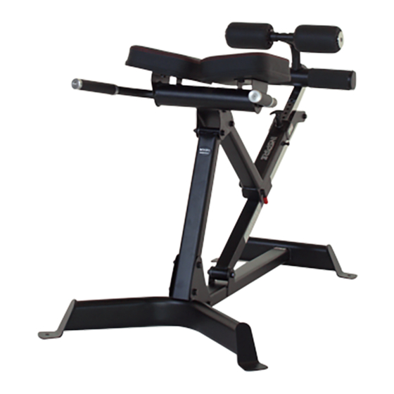
Summary of Contents for Inspire HYP1
- Page 1 ASSEMBLY & OPERATION MANUAL RECORD SERIAL NUMBER HERE www.inspirefitness.com by Health In Motion LLC Feb. 2015...
-
Page 2: Table Of Contents
TABLE OF CONTENTS Section Description……………………………………………………. Page Important Safety Instructions………………………………………. Parts List…………………………………………………………………………. Exploded Diagram………………………………………………………….. Assembly Instructions……………………………………………………. Decal Reference…………………………………………………………….. Decal Placement……………………………………………………………… General Maintenance Information…….…………………………… Maintenance Schedule…….……………………………………………… Limited Warranty…………………………………………………………….. -
Page 3: Important Safety Instructions
• Keep the hyper extension away from walls and clear of any obstructions and furniture. • Stop immediately if you experience shortness of breath, pain, or dizziness during your workout. Inspire Fitness strongly recommends consulting your doctor before starting an exercise program. TOOLS REQUIRED FOR ASSEMBLY •... -
Page 4: Parts List
PARTS & HARDWARE LIST Item # Description Part Number Quantity Front Foot Tube Assembly GM582-200-001 Stabilizer Assembly GM582-100-001 PZ Front Support Tube Assembly GM582-270-001PZ Handle Assembly GM582-250-001PZ Adjustment Tube Assembly GM582-230-001PZ Pivot Tube Assembly GM582-210-001PZ Lower Adjustment Tube Assembly GM582-220-001PZ Upper Adjustment Tube Assembly GM582-240-001PZ Leg Rest Assembly... -
Page 5: Exploded Diagram
11 11 39 39 39 39 22 22 16 16 22 22 43 43 30 30 29 29 29 29 33 33 12 12 39 39 21 21 39 39 31 31 39 39 39 12 12 12 21 21 21 21 11 11 11 11... -
Page 6: Assembly Instructions
12 12 39 39 21 21 39 39 Step 1 Combine the Front Foot Tube Assembly (1) and the Stabilizer Assembly (2) ɸ using 2- Hex Bolts M12x95 (21), 4- Flat Washers 12 (39), and 2- Lock Nuts M12 (12). Hand Tighten Only. - Page 7 Step 2 Attach the Pivot Tube Assembly (6) to the Stabilizer Assembly (2) using 1- Hex Bolt ɸ M12x95 (21), 2- Flat Washers 12 (39), and 1- Lock Nut M12 (12). Make sure the Hex Bolt M12x95 (21) goes through Spacer 2 (32) inside the Pivot Tube Assembly (6).
- Page 8 Step 3 Loosen the Pop-pin (26) and insert the Lower Adjustment Tube Assembly (7) into the Pivot Tube Assembly (6). PAGE 6...
- Page 9 Step 4 Attach the Adjustment Tube Assembly (5) to the Lower Adjustment Tube Assembly (7) ɸ usinge 1- Hex Bolt M12x95 (21), 2- Flat Washers 12 (39), and 1- Lock Nut M12 (12). Make sure the Hex Bolt M12x95 (21) goes through Spacer 2 (32) inside the Lower Adjustment Tube Assembly (7).
- Page 10 Step 5 Attach the Aluminum Cap (38), Foot Roller (10), Plastic Washer (40), and Foam Stopper (41) to the Leg Rest Assembly (9) using 1- Flathead Screw M10x25 (37). Repeat for both sides. TIGHTEN HARDWARE FROM THIS STEP ONLY. PAGE 8...
- Page 11 30 30 29 29 29 29 33 33 Step 6 Attach the Leg Rest Assembly (9) to the Upper Adjustment Tube Assembly (8) using ɸ 2- Hex Bolts M10x60 (33), 4- Flat Washers 10 (29) and 2- Lock Nuts M10 (30) Unscrew the Pop-pin and insert the Upper Adjustment Tube Assembly (8) into Adjustment Tube Assembly (5).
- Page 12 12 12 39 39 39 39 21 21 Step 7 Attach the Front Support Tube Assembly (3) to the Front Foot Tube Assembly (1) using ɸ 2- Hex Bolts M12x95 (21), 4- Flat Washers 12 (39), and 2- Lock Nuts M12 (12). HAND TIGHTEN ONLY.
- Page 13 12 12 12 39 39 39 39 39 39 Step 8 Attach the Handle Assembly (4) to the Adjustment Tube Assembly (5) using 2- Hex ɸ Bolts M12x95 (21), 4- Flat Washers 12 (39), and 2- Lock Nuts M12 (12). Attach the Handle Assembly (4) to the Front Support Tube Assembly (3) using 1- Hex ɸ...
- Page 14 29 29 22 22 29 29 22 22 Default Orientation Step 9 Attach the Back Pad Assembly (11) onto the Handle Assembly (4) using 2- Hex Bolts ɸ M10x25 (22) and 2- Flat Washers 10 (29). Repeat for both sides. Note: Back Pads can be oriented in either direction.
-
Page 15: Decal Reference
DECAL REFERENCE Page 13... -
Page 16: Decal Placement
DECAL PLACEMENT "Checklist" (on the reverse side) "Warning Label" "Warning, Pinch Point!" (Side of the plate) "Warning, Pinch Point!" Serial Number (Bottom of the Assembly) PAGE 14... -
Page 17: General Maintenance Information
GENERAL MAINTENANCE INFORMATION Warning: DO NOT place styrofoam or printed materials on the orthopedic pads. Over time, these may stick to the pads and mar the surface. Do not leave items sitting on the orthopedic pads, these pads have a special density that takes shape to objects and small objects will leave imprints in the surface that may take time to come out. -
Page 18: Maintenance Schedule
MAINTENANCE SCHEDULE HOME ROUTINE ENTRY DATE MAINTENANCE Inspect: Links, Pull Pins, WEEKLY Spring Clips, Swivels, Weight Stack Pins WEEKLY Clean: Upholstery Inspect: Accessory Bars 3 MONTHS and Handles 3 MONTHS Inspect: All Decals Inspect: All Nuts and 3 MONTHS Bolts. Tighten if Needed Inspect: Anti-Skid 3 MONTHS surfaces... -
Page 19: Limited Warranty
This is the only express warranty applicable to Health In Motion’s “Inspire” branded strength products. Health In Motion neither assumes nor authorizes anyone to assume for it any other express warranty.


Need help?
Do you have a question about the HYP1 and is the answer not in the manual?
Questions and answers