
Related Manuals for Inspire Dual Chest/Shoulder


Summary of Contents for Inspire Dual Chest/Shoulder
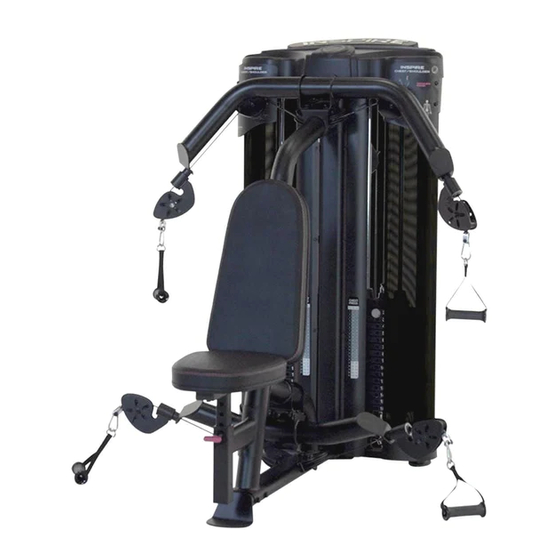
- Page 1 ASSEMBLY & OPERATION MANUAL DUAL Chest/Shoulder RECORD SERIAL NUMBER HERE www.inspirefitness.com by Health In Motion LLC 1-10-17...
- Page 2 Use the parts list included in this manual to verify that all parts are accounted for before assembly. If any parts are missing, contact the dealer of this Dual Chest/Shoulder machine for replacement parts or call Inspire at 877-738-1729. Make sure that adequate room has been cleared before attempting to build your Dual Chest/Shoulder machine.
-
Page 3: Table Of Contents
TABLE OF CONTENTS Section Description……………………………………………………. Page Important Safety Instructions………………………………………. Tools Required………………………………………………………………… Parts & Hardware List……………………………………………………. Cable Charts…………….……………………………………………………. Assembly Instructions……………………………………………………. Decal Reference……………………………………………………………… Decal Placement……………………………………………………………. Options, Training Tips…………………………………………………… Maintenance Schedule…….……………………………………………… Limited Warranty…………………………………………………………….. -
Page 4: Important Safety Instructions
Chest/Shoulder machine while it is in use. • Keep children off the Dual Chest/Shoulder machine at all times. • Keep the Dual Chest/Shoulder machine away from walls and clear of any obstructions. • Stop immediately if you experience shortness of breath, pain, or dizziness during your workout. - Page 5 DUAL CHEST/SHOULDER PARTS & HARDWARE LIST Item Parts Description Qty Rec'd Item Hardware Description Qty Rec'd Main Frame M10 x 25 Hex Bolt Guide Cable Support M10 x 95 Hex Bolt Upright 1 M10 x 75 Hex Bolt Upper Arm...
- Page 6 DUAL LINE CHEST/SHOULDER CABLE CHART Weight Cable p/n GM881-500-002 1291 mm Main Cable p/n GM884-500-001 5722 mm Guide Cable p/n GM881-500-001 1233 mm Cable lengths are in millimeters and for reference only. Cable lengths could change at any time without notice. Page 3...
-
Page 7: Assembly Instructions
ASSEMBLY INSTRUCTIONS Page 4... - Page 8 Step 2 4 - M10 x 75 Hex Bolts Guide Cable 8 - M10 Flat Washers Support 4 - M10 Locknuts Upright 1 Step 1 Main Frame 2 - M10 x 25 Hex Bolts 2 - M10 x 95 Hex Bolts 6 - M10 Flat Washers 2 - M10 Locknuts Step 1: Attach Upright 1 to the Main Frame using:...
- Page 9 Upright 1 Adjustment Foot Step 3 2 - M10 x 125 Hex Bolts 4 - M10 Flat Washers 2 - M10 Locknuts Base Frame 2 – M10 x 125 Hex Bolts Step 3: Attach the Base Frame to the Upright 1 using: 4 –...
- Page 10 Step 4 4 - M10 x 125 Hex Bolts 8 - M10 Flat Washers 4 - M10 Locknuts Upright 1 Upright 2 Base Frame Step 4: Attach the Upright 2 to the Base Frame and Upright 1 using: 4 – M10 x 125 Hex Bolts 8 –...
- Page 11 Step 5 Upright 2 2 - M10 x 95 Hex Bolts 1 - M10 x 100 Hex Bolts 2 - M10 x 20 Hex Bolts 8 - M10 Flat Washers 3 - M10 Locknuts Lower Arm Mount Seat Frame Base Frame Step 5: Attach the Lower Arm Mount to the Base Frame and Upright 2 and the Seat Frame to the Upright 2 using: 2 –...
- Page 12 Step 6 4 - M10 x 25 Hex Bolts 8 - M10 Flat Washers 4 - M10 Locknuts Lower Arm Mount Lower Arm 4 – M10 x 25 Hex Bolts Step 6: Attach the Lower Arm to the Lower Arm Mount using: 8 –...
- Page 13 Step 7 4 - M10 x 25 Hex Bolts 8 - M10 Flat Washers 4 - M10 Locknuts Upper Arm Upright 2 Step 6: Attach the Upper Arm to the Upright 2 using: 4 – M10 x 25 Hex Bolts 8 –...
- Page 14 Step 8 1 - M8 x 20 Hex Bolts 1 - M8 Flat Washer 1 - M10 x 75 Hex Bolts 2 - M10 x 90 Hex Bolts Upper Pulley Mount, Left Top Weight 6 - M10 Flat Washers Stop Assembly 3 - M10 Locknuts Front of weight plate has recessed Guide Rods...
- Page 15 Step 9 1 - M8 x 20 Hex Bolts 1 - M8 Flat Washer Upper Pulley Mount, Right 1 - M10 x 75 Hex Bolts 2 - M10 x 90 Hex Bolts 6 - M10 Flat Washers 3 - M10 Locknuts Top Weight Stop Assembly Front of weight plate has recessed...
- Page 16 Step 10 4 - M10 x 25 Hex Bolts 8 - M10 Flat Washers 4 - M10 Locknuts Lower Pulley Mount Upright 1 Step 10: Attach the Lower Pulley Mount to the Upright 1 using: 4 – M10 x 25 Hex Bolts 8 –...
- Page 17 Step 11 Upper Pulley Mount, Right Upper Pulley Mount, Left Upper Cable Routing Top Weight Stop Weight Cable Top Weight Stack Floating Pulley Cable Adapter Jam Nut Cable DUAL LINE CHEST/SHOULDER CABLE CHART Selector Stem Floating Pulley (Side View) Thread bolt completely into selector stem and tighten jam nut Weight Cable p/n GM881-500-002...
- Page 18 Step 12 Pulley 2 Route Cables Open Pulley Slot #1 Pulley 4 Pulley 3 Pulley 1 Floating Pulleys Pulley 5 Pulley 6 Pulley 7 Pulley 8 Swivel Pulley Lower Pulley Mount UAL LINE CHEST/SHOULDER CABLE CHART Pulley 5 Main Cable Weight Cable p/n GM881-500-002 “U”...
- Page 19 Step 13 Upright 2 4 - M10 x 50 Hex Bolts 8 - M10 Flat Washers 4 - M10 Locknuts Pulley 9 Pulley 10 (Right side of machine) Pulley 11 Pulley 12 (Right side of machine) Base Frame Pulley 9 & Pulley 10 Cable Guide Pulley 11 &...
- Page 20 Step 14 Guide Cables Install Guide Cables Floating Pulley Assembly DUAL LINE CHEST/SHOULDER CABLE CHART Weight Cable p/n GM881-500-002 Rear Shroud Plate Support Main Cable p/n GM884-500-001 Step 15 1 - M8 x 100 Hex Bolt Springs 2 - M8 Flat Washers 1 - M8 Locknuts Guide Cable p/n GM881-500-001...
- Page 21 Step 16 2 - M10 x 100 Hex Bolts Upright 2 2 - M10 Flat Washers Step 17 Back Pad 2 - M10 x 50 Hex Bolts 2 - M10 Flat Washers Seat Pad Seat Orientation Seat Stem 2 – M10 x 100 Hex Bolts Step 16: Attach the Back Pad to the Upright 2 using: 2 –...
- Page 22 “D” Handles Assembly, Long “D” Handle Assembly Adjustable Pulley Step 18: Attach the “D” Handle Assembly to the “U” Bracket Assembly in the Upper and the Rubber “D” Handle Assembly, Long to the Lower Swivel Pulleys. NOTE: At this point it is necessary to seat the cables. Start by verifying that cables are centered in the grooves of all pulleys.
- Page 23 Step 20 Insert Shroud into Metal Pieces Upper Metal Shroud Fabric Shroud Lower Metal Shroud Step 20: To install Fabric Shroud, start from one end of the Lower Metal Shroud and insert the Fabric Shroud inwards as shown. Make sure to have the same orientation as shown or else the fabric shroud will be installed backwards.
- Page 24 Shroud Assembly Step 22 3 - M10 x 50 Fully Threaded Hex Bolts 3 - M10 Flat Washers Step 21 1 - M10 x 25 Button Head Bolt 2 - M10 x 70 Hex Bolts 3 - M10 Flat Washers Step 21: Attach the Lower Metal Shroud to the Upright 1 1 –...
- Page 25 Step 23 10 – M6 x 12 Button Head Bolts 10 – M6 Flat Washers Right Shroud Plate Left Shroud Plate Step 23: Attach Right and Left Metal Shroud Plates to Upright 1 using: 10 – M6 x 12 Button Head Bolts 10 –...
- Page 26 Step 24 6 - M8 x 12 Button Head Bolts 6 - M8 Flat Washers Upper Metal Shroud Metal Shroud Placard Step 24: Attach the Metal Shroud Placard to the Upper Metal Shroud using: 6 – M8 x 12 Button Head Bolts 6 –...
- Page 27 Step 25 Rubber tablet holder only fits one way. Make sure the outer edge of the tablet holder sits flat 1 - M8 x 12 Button Head Bolt Rubber Tablet Holder against the molded cap. 1 - M8 Flat Washer 2 - M10 x 25 Button Head Bolts 2 - M10 Large OD Flat Washers Rubber Cup...
-
Page 28: Decal Reference
DECAL REFERENCE 877-738-1729 8,870,718. PAGE 25... - Page 29 DECAL REFERENCE Page 26...
-
Page 30: Decal Placement
DECAL PLACEMENT “Inspire Logo” Globe Logo Label (50mm) Round “This product Patent Pending” placed behind Back Rest piece (60 x 40) “NOTICE” on side of upright, beside head pad (40 x 170) “WARNING Use only genuine INSPIRE replacement parts” on side of upright. - Page 31 ACCESSORIES • 2 – “D” Handles • 2 – “D” Handle Assembly, Long GYM OPTIONS • 2- Heavy Stack (50lbs. each) Training Tips CONSULT A PHYSICIAN BEFORE STARTING ANY EXERCISE PROGRAM 1. Always warm up before you start weight training. This helps get your muscles warm and prevents injury.
- Page 32 GENERAL MAINTENANCE INFORMATION • Periodically inspect the cables for splitting, cracking or fraying. Also, watch for bulging or flat areas in the cable. • Immediately replace cables at the first signs of damage or wear. Never use equipment with damaged or worn cables. •...
-
Page 33: Maintenance Schedule
MAINTENANCE SCHEDULE COMMERCIAL/ HOME ROUTINE ENTRY DATE LIGHT COMMERCIAL MAINTENANCE MAINTENANCE Inspect: Links, Pull Pins, Spring Clips, DAILY WEEKLY Swivels, Weight Stack Pins. DAILY WEEKLY Clean: Upholstery. Inspect: Cables and DAILY WEEKLY their Fittings for wear or looseness. Inspect: Tautness of DAILY WEEKLY all Shrouds. - Page 34 This is the only express warranty applicable to Health In Motion’s “Inspire” branded strength products. Health In Motion neither assumes nor authorizes anyone to assume for it any other express warranty.
Need help?
Do you have a question about the Dual Chest/Shoulder and is the answer not in the manual?
Questions and answers