
Related Manuals for GEA MAXA L


Summary of Contents for GEA MAXA L
- Page 1 GEA Hilge MAXA L MAXANA L 65-250 Installation and operating instructions English Translation of the original operating manual BA.223.LYY.001.04.17.GB engineering for a better world GEA Hilge...
- Page 2 Annex VII, Part B and we obligate to provide these upon reasoned request from the individual national authorities by data transfer. HILGE GmbH & Co.KG Authorized person for compiling and handing over Hilgestraße 37-47 technical documentation: 55294 Bodenheim, Germany Bodenheim, 2016-04-07 Franz Bürmann Managing Director GEA Hilge...
-
Page 3: Table Of Contents
1. Introduction _________________________________________________ 5 1.1 Target group_________________________________________________________________5 1.2 Symbols and formatting ________________________________________________________5 1.3 References to the document ____________________________________________________5 2. Safety ______________________________________________________ 6 2.1 Instructions for the operator _____________________________________________________6 2.1.1 General information_______________________________________________________6 2.2 Safety instructions in the operating manual _________________________________________6 2.3 Identification of instructions in the operating manual __________________________________7 2.3.1 Structure of safety instructions ______________________________________________7 2.4 Qualifications and training of personnel ___________________________________________8 2.5 Hazards caused by failure to follow the safety instructions _____________________________8... - Page 4 4.5.3 Checking the direction of rotation after connection______________________________ 29 5. Start-up / shut-down__________________________________________ 30 5.1 Start-up ___________________________________________________________________ 30 5.1.1 Check application conditions ______________________________________________ 30 5.1.2 Starting up the pump ____________________________________________________ 30 5.1.3 Functional check of the mechanical seal _____________________________________ 30 5.2 Shut-down _________________________________________________________________ 31 5.2.1 Shutting down the pump __________________________________________________ 31 5.2.2 Cleaning the pump after shut-down _________________________________________ 31...
-
Page 5: Introduction
Introduction 1. Introduction Overview This section describes the requirements which are important for reading and understanding this manual. You will learn the symbols and formats that make the reading easier. 1.1 Target group This operating manual is intended for: • the operators of the pump •... -
Page 6: Safety
Safety 2. Safety Overview This section describes what you have to consider for your own safety. You will learn the structure and identifica- tion of safety instructions. Read this important section attentively! 2.1 Instructions for the operator All our pumps are professionally packed before they leave our 2.1.1 General information warehouse to avoid damage during transport. -
Page 7: Identification Of Instructions In The Operating Manual
Safety 2.3 Identification of instructions in the operating manual The safety instructions presented in this operating manual are Symbol identified as shown below. ATTENTION Fig. 1 Symbol for safety instructions A: Failure to follow these safety instructions can endanger per- sonnel. -
Page 8: Qualifications And Training Of Personnel
Safety 2.4 Qualifications and training of The employees operating, maintaining, inspecting, and in- stalling the pump must have the appropriate qualifications for personnel this work. The operator must define in detail the tasks for which the employees are responsible, the tasks of which they are in charge, and the manner in which they are supervised. -
Page 9: Safety Instructions For The Operator / User
Safety 2.7 Safety instructions for the operator / user CA UTION Hot or cold mechanical components! Serious bodily injury. Take structural measures to prevent contact with them! WARNING Trapping hazard! Death, serious bodily injury, damage to property. Do not remove protection against contact with moving parts (e.g. -
Page 10: Improper Operation
Safety 2.9 Improper operation The operational reliability of the delivered machine can be guaranteed only when it is used properly as indicated in the following sections. The given limit values may not be exceeded under any cir- cumstances. 2.10 Transport WARN ING Falling loads! Death, serious bodily injury, damage to property. -
Page 11: Cleaning
Safety 2.11 Cleaning CIP and SIP methods must be in accordance with the latest current guidelines of the EC. When special cleaning agents and methods are used, the supplier must confirm that they are safe for the materials in- volved. WARNING Pressure surge! Death, serious bodily injury, damage to property. -
Page 12: Product Description
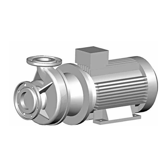
Product description 3. Product description Overview This section describes the pump as well as it’s design and application. Section „Technical Data“ describes limits for application. You must know and keep these limits. 3.1 Pump overview 0156 0802 0153 0102 0340 0183 0156 0802... -
Page 13: Description
Product description 3.2 Description The pump is a single-stage end-suction centrifugal pump with main dimensions and characteristic according to DIN EN 733 resp. DIN EN 22858. 3.2.1 Areas of application Pumps of the standard design are used for: Standard design •... -
Page 14: Technical Data
Product description may occur during use and operation. 3.4 Technical data WARN ING Overloading the pump! Death, serious bodily injury, damage to property. Use the pump only under the indicated operating condi- tions. Also avoid short over pressure situation (e.g. caused by pressure surge). -
Page 15: Nameplate
Product description The nameplate is shown in fig. 4 and contains the following 3.4.3 Nameplate data: HILGE GmbH & Co. KG Hilgestraße - D - 55294 Bodenheim Pump -Type m3/h min -1 Doc. -No. MADE BY HILGE Fig. 4 HILGE nameplate, example •... -
Page 16: Weights
Product description 3.5 Weights Design features of the described standard pumps: Caution: The weights can - depending on design and accessories - dif- fer from those presented. The manufacturer gives you when given the pump / order number precise information. •... - Page 17 Product description 100-250 132M 125(150) 100(125) 100-250 11,0 160M 125(150) 100(125) 100-250 15,0 160L 125(150) 100(125) 125-250 132M 150(200) 125(150) 125-250 11,0 160M 150(200) 125(150) 125-250 15,0 160L 150(200) 125(150) 125-250 18,5 180M 150(200) 125(150) 125-250 22,0 180L 150(200) 125(150) Tab.
-
Page 18: Noise Emissions
Product description Measured values according to DIN EN ISO 3746 for pump 3.5.1 Noise emissions units; uncertainty of measurement 3dB (A). Motor power [dB (A) 18,5 Tab. 6 Noise emissions MAXA 2-pole Motor power [dB (A) 18,5 Tab. 7 Noise emissions MAXA 4-pole BA.223.LYY.001.01.10.GB... - Page 19 Product description Motor power Number of pols [dB (A) 0,75 18,5 Tab. 8 Noise emissions MAXANA 2-pole Motor power Number of pols [dB (A) 0,55 0,75 Tab. 9 Noise emissions MAXANA 4-pole Noise emissions caused by a pump are significantly affected by its application and construction.
-
Page 20: Maximum Operating Temperatures
Product description 3.5.2 Maximum operating temperatures CAUTION Exceeding the max. permitted operating temperature! Death, serious bodily injury, damage to property. Never exceed the specified operating temperatures! Tab.10 lists the maximum permissible temperatures. Design Temp. [°C] Standard design Special design Sterilisation Tab. -
Page 21: Mounting, Installation And Connection
Mounting, installation and connection 4. Mounting, installation and connection Overview This chapter is intended for the maintenance and repair personnel. This section describes how to mount, adjust and install the pump.You get to know what to consider when you connect the pump to the electric mains supply and how to improve the flow in order to avoid dry running of the shaft seals. -
Page 22: Installation In The Pipeline
Mounting, installation and connection Align the pump in this way: 1. Use an engineer’s spirit level laid across the machined surface of the discharge branch connection to align the assembly. 2. After aligning the assembly, tighten the mounting bolts uniformly in a crosswise manner. 4.3 Installation in the pipeline WARN ING Mechanical overload! - Page 23 Mounting, installation and connection For example see Fig. 5. 0433.00 Fig. 5 Lubrication between slide surfaces • P - pump side • 0433.00 - mechanical seal • L - lubrication • A - atmosphere side CA UTION Dry running! Damage to property. The suction line must be absolutely leak proof and laid in such a way that no air pockets can form.
-
Page 24: Space Requirements
Mounting, installation and connection Fig. 6 Installation in the pipeline above: gravity feed mode below: suction mode P - pump M - motor 4.3.1 Space requirements ATTENTION Overheating! Damage to property. Ensure sufficient ventilation. Make sure not to re absorb warm cooling air. Consider other heat sources in the area. -
Page 25: Reduction Of Noise And Vibration
Mounting, installation and connection Noise and vibration are generated by the pulsating flow of the 4.3.2 Reduction of noise and vibration rotors and by the flow in pipes and fittings. The effect on the environment is subjective and depends on correct installation and the state of the remaining system. -
Page 26: Connections
Mounting, installation and connection 4.4 Connections HILGE pumps with single-chamber mechanical seals are 4.4.1 Flushing connection for the single equipped with a seal cartridge. mechanical seal The flushing liquid is located in this seal cartridge. It passes over into the liquid pumped via a throttle gap (lost flush). Fig. -
Page 27: Flushing Connection For Double Mechanical Seal
Mounting, installation and connection 4.4.2 Flushing connection for double mechanical seal 4.4.2.1 Double mechanical seal HILGE pumps with double mechanical seal are equipped with a seal cartridge. Depending on the seal design the barrier or flushing fluid flows inside this seal cartridge. The connection must be carry out as shown in Fig. -
Page 28: Double Mechanical Seal - Tandem Arrangement
Mounting, installation and connection 4.4.2.2 Double mechanical seal - tandem arrangement In order to continue functioning, the mechanical seals require Flushing liquid a flushing liquid, some of its purposes being: • Preventing leaks • Dry-run protection • Lubrication and cooling of the mechanical seals •... -
Page 29: Star Connection
Mounting, installation and connection Star-connection 3-phase system for high voltage. 4.5.1 Star connection Connect the pump as specified in the order documents. The figure below shows the scheme for star connection. Fig. 11 Star connection Delta-connection for low voltage. 4.5.2 Delta connection Connect the pump as specified in the order documents. -
Page 30: Start-Up / Shut-Down
Start-up / shut-down 5. Start-up / shut-down Overview This section describes how to start up and shut down the pump. You get to know which inspections contribute to failure-free operation and increased life of the pump. 5.1 Start-up 5.1.1 Check application conditions Check the application conditions of the pump in this way: 1. -
Page 31: Shut-Down
Start-up / shut-down 5.2 Shut-down 5.2.1 Shutting down the pump CA UTION Pressure surge! Death, serious bodily injury, damage to property. Always close shut-off devices slowly! A pressure surge is an abruptly pressure increasing in the What is a pressure surge? system. -
Page 32: Maintenance / Servicing
Maintenance / servicing 6. Maintenance / servicing Overview This chapter is intended for the maintenance and repair personnel. This section gives important information concerning maintenance and servicing of the pump. Read this section before you carry out maintenance work or troubleshooting measures! 6.1 Safety instructions for maintenance, inspection and installation work... -
Page 33: Maintenance Of The Pump
Maintenance / servicing WARNING Missing protection and safety equipment! Death, bodily injury, damage to property. Immediately after completing the work install the protec- tion and safety equipment and make sure it functions. CA UTION Improper tools! Damage to property. In accordance with the design standard (3A0.01 to 3A3.37), all tools, possible support surfaces, and other auxiliary materials must ensure that all parts of the pump can be assembled without damage (e.g.scratches). -
Page 34: Bearing Lubrication
Maintenance / servicing 6.4.3 Bearing lubrication 6.4.3.1 Cylinder bearing greases Use only the cylinder bearing greases listed here or demon- strably comparable ones to lubricate the roller bearings. Bearing temperature ≤ 120 °C Bearing temperature ≤ 60 °C – Danger of water entering Manufacturer ARAL HL 3... -
Page 35: Re Lubrication L-Bearing
Maintenance / servicing Lubricate the roller bearings in accordance to the table below. 6.4.4 Re lubrication L-bearing The mentioned data apply to normal operating conditions. CA UTION Faulty lubrication of the roller bearings! Damage to property. Do not use a higher quantity of grease to lubricate the bearings as per description! Lantern Motor size... -
Page 36: Assembly / Disassembly
Maintenance / servicing 6.5 Assembly / Disassembly 6.5.1 Parts overview 0902.02 | 0920.04 | 0934.00* 0902.01 | 0920.22 | 0934.03** 0491.00 0433.00 0801.00 0636.00 0102.00 0636.02 0412.04 0922.00 0940.00 0211.00 0340.00 0504.09 0230.00 0167.00 0360.02 0902.06 | 0920.09 | 0934.06 0412.02 0412.00 0507.02... -
Page 37: Instructions For Disassembly
Maintenance / servicing Qty. Part No. Description Qty. Part No. Description 0102.00 volute casing 0801.00 flanged motor 0161.00 backplate 0902.01 stud 0167.00 casing backplate liner 0902.02 stud 0211.00 pump shaft 0902.06 stud 0230.00 impeller 0902.08 stud 0321.00 grooved ball bearing 0904.06 grub screw 0340.00... -
Page 38: Assembly Of Maxa-L
Maintenance / servicing Important aspects! Use tools from HILGE assembly tool kit in order to assem- ble the pump without damages and scratches. To guarantee a good seal, use only O-ring seals with the original dimensions. Never use grease which contains mineral oil when assem- bling the wet end parts Replace mechanical seals always in complete assembly. -
Page 39: Overview Mechanical Seal Arrangements
Maintenance / servicing 6.5.5 Overview mechanical seal Arrangements Fig. 14 Mechanical seal arrangements Variant Seal type Characteristic Page Single mechanical seal Seat located in casing backplate liner Single mechanical seal Seat located in sealing seal cartridge - with casing backplate liner Single mechanical seal Seat located in backplate, solid Single mechanical seal... -
Page 40: Assembly Of The Single Mechanical Seal (A)
Maintenance / servicing 6.5.6 Assembly of the single mechanical seal (A) 0412.02 0934.11 0920.15 0902.08 0433.00 0491.00 0504.09 0167.00 0161.00 Fig. 15 Single mechanical seal (A) • Single mechanical seal Features of the mechanical seal • Seat in seal cartridge 0491.00 •... -
Page 41: Assembly Of The Single Mechanical Seal (B)
Maintenance / servicing 6.5.7 Assembly of the single mechanical seal (B) 0161.00 0504.09 0433.00 0516.01 0167.00 Fig. 16 Single mechanical seal (B) • Single mechanical seal Features of the mechanical seal • Seat in casing backplate liner 0167.00 Assemble the mechanical seal in this way: The part numbers given in the following instructions may be Please note found in tab. -
Page 42: Assembly Of Single Mechanical Seal (C)
Maintenance / servicing 6.5.8 Assembly of single mechanical seal (C) 0433.00 0504.09 0161.00 Fig. 17 Single mechanical seal (C) • Single mechanical seal Features of the mechanical seal • Seat in solid backplate 0161.00 Assemble the mechanical seal in this way: The part numbers given in the following instructions may be Please note found in tab. -
Page 43: Assembly Of Single Mechanical Seal (D)
Maintenance / servicing 6.5.9 Assembly of single mechanical seal (D) 0471.00 0904.12 0433.00 0504.09 0491.00 0914.09 0934.23 0412.02 0902.08 0161.00 0920.15 0934.11 Fig. 18 Single mechanical seal (D) • Single mechanical seal Features of the mechanical seal • Seat in seal cartridge 0491.00 •... -
Page 44: Assembly Of Double Mechanical Seal (E)
Maintenance / servicing 6.5.10 Assembly of double mechanical seal (E) 0161.00 0167.00 0491.00 0433.00 0433.01 0471.00 0918.00 0412.03 0902.08 0412.02 0920.15 0934.11 Fig. 19 Double mechanical seal (E) • Double mechanical seal, tandem - arrangement Features of the mechanical seal •... -
Page 45: Assembly Of The Impeller And Volute Casing
Maintenance / servicing 15. Push the rotating part of the mechanical seal 16. Pull the assembly sleeve off the shaft 0211.00. 0433.00 onto the shaft. Use the assembly sleeve from step 8. to do this. OPTIMOL paste TA, assembly tool kit auxiliary material 6 Assembly tool kit tool 3B - for Ø... - Page 46 Maintenance / servicing 7. Tighten the impeller nut 0922.00 by hand. Let 8. Wet O-ring 0412.04 with clean water and slide it over the impeller nut 0922.00 into the gap about 5 mm space for the O-ring 0412.04. between impeller nut 0922.00 and impeller 0230.00.
-
Page 47: Troubleshooting
Maintenance / servicing 15. Tighten the hexagon nuts 0920.04 in the order shown below. Torque: M10 - 37, M12 - 65 Nm. Fig. 34 Tightening order 6.6 Troubleshooting Problem Cause Remedy 1. Incorrect electrical hook-up (2 phases). 1. Check the electrical connections and cor- Pump does not 2. -
Page 48: Disposal
This product or parts of it must be disposed of in an environ- mentally sound way: 1. Use the public or private waste collection service. 2. If this is not possible, contact the nearest GEA Hilge company or service workshop. BA.223.LYY.001.01.10.GB... -
Page 49: Hilge Assembly Tool Kit
Maintenance / servicing 6.8 HILGE assembly tool kit Remove and install the mechanical seals safely and reliably by using tools of the HILGE assembly tool kit. Fig. 35 HILGE assembly tool kit 6.8.1 Content and use Item Description - shaft diameter (fig.) •... -
Page 50: Certificate Of Non-Objection
Certificate of non-objection 7. Certificate of non-objection Overview This section contains a certificate of non-objection. In case of inspection or repairing send the pump including these certificate to HILGE. 7.1 Certificate of non-objection The following pump and its accessories, together with this certificate of non-objection, are herewith contracted out by the undersigned for inspection/repair: •... - Page 52 Responsibility GEA-versity GEA Group is a global engineering company with multi-billion euro sales and operations in more than 50 countries. Founded in 1881, the company is one of the largest providers of innovative equipment and process technology. GEA Group is listed in the STOXX Europe 600 Index.
Need help?
Do you have a question about the MAXA L and is the answer not in the manual?
Questions and answers