
Related Manuals for Scotchman GAA-500-90 DT20


Summary of Contents for Scotchman GAA-500-90 DT20
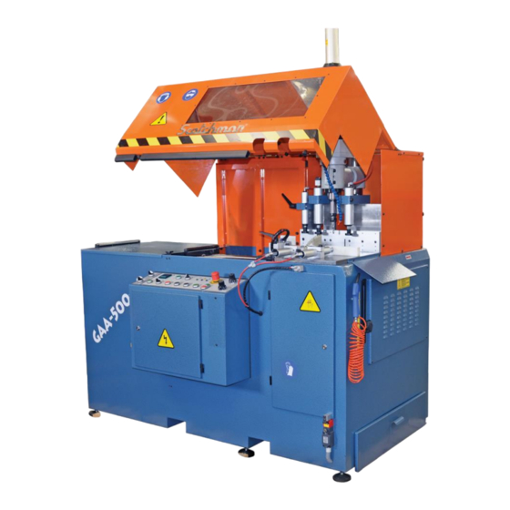
- Page 1 You have downloaded a manual for our MODEL GAA-500-90 DT20 AUTO UP-CUT NON-FERROUS SAW RETURN TO CONTENTS...
- Page 2 MODEL GAA-500-90 DT20 AUTO UPCUT COLD SAW PRINTED MAY 2024 SCOTCHMAN INDS. - 180 E US HWY 14 - PO BOX 850 - PHILIP, SD 57567 Call: 1-605-859-2542 RETURN TO CONTENTS...
- Page 3 GAA-500-90 DT20 RETURN TO CONTENTS...
- Page 4 SU-280-G BAND SAW 66 to 176 TON PRESSPRO HYDRAULIC PRESSES SCOTCHMAN INDS. - 180 E US HWY 14 - PO BOX 850 - PHILIP, SD 57567 Call Toll Free in USA: (800) 843-8844 Call Direct: 1 -605-859-2542 Fax: (800)-843-5545 Email: info@scotchman.com...
-
Page 5: Table Of Contents
TABLE OF CONTENTS Contents TABLE OF CONTENTS ..........................5 1.0 INTRODUCTION ..........................7 1.1 Legislation ............................7 1.2 Warranty ............................7 2.0 GENERAL MACHINE INFORMATION ..................8 2.1 Machine Identification Data ......................8 2.2 Technical Data ........................... 8 2.3 Machine Dimensions ......................... 9 2.4 Cutting Capacity .......................... - Page 6 6.0 RECOMMENDATIONS AND MAINTENANCE ................23 6.1 Type and Frequency of Inspections ....................23 6.2 Qualified Personnel for Maintenance and Repair Work ............. 23 6.3 Manufacturer’s Recommendations ....................23 6.4 Voltage Conversions ........................24 6.5 PLC and Sensor Troubleshooting and Adjustment ..............26 7.0 PARTS DIAGRAMS AND SCHEMATICS ..................
-
Page 7: Introduction
2004/108/CEE On “Electromagnetic Compatibility”. 1.2 Warranty Scotchman Industries, Inc. will, within two years of the date of purchase, replace F.O.B. the factory or refund the purchase price for any goods which are defective in materials or workmanship, provided the buyer, at the seller’s option, returns the defective goods freight and delivery prepaid to the seller, which shall be the buyer’s sole and exclusive remedy for defective goods. -
Page 8: General Machine Information
2.0 GENERAL MACHINE INFORMATION 2.1 Machine Identification Data MODEL - GAA-500-90 DT20 ___________________________ SERIAL NUMBER ___________________ YEAR OF MANUFACTURE ➢ NOTE: IN ORDER TO REQUEST SPARE PARTS, WHETHER COVERED BY THE WARRANTY OR NOT, ALWAYS INDICATE THE MODEL AND SERIAL NUMBER OF THE MACHINE, AS WELL AS THE NAME OF THE PART AND THE PART NUMBER THAT APPEARS IN THE FOLLOWING PARTS DIAGRAMS WITHIN THIS MANUAL. -
Page 9: Machine Dimensions
2.3 Machine Dimensions Height with hood open is 6ft. Height to saw table is 38.4”. RETURN TO CONTENTS... -
Page 10: Cutting Capacity
2.4 Cutting Capacity RETURN TO CONTENTS... -
Page 11: Electrical Data
BEFORE signing the delivery paperwork. If damage is seen, refuse the shipment and notify Scotchman. DO NOT ACCEPT DAMAGED EQUIPMENT. This makes filing damage claims with the shipping company impossible and will make the customer responsible for the damage repair costs. - Page 12 Once the machine is connected, verify that the saw blade rotation is away from the operator when the operator is standing in front of the machine. If the saw blade rotation is wrong, swap two phases of incoming power to the machine. Then check for proper rotation again. ➢...
-
Page 13: Pressure Regulator
4.3 Pressure Regulator The air inlet location is shown below. The air regulator must be set at 6.5 to 7.2 bar (90 to 105 psi). The red knob on top is used to turn the air supply on or off. Do not add oil to the regulator. The pneumatic components of this machine are internally lubricated with grease. -
Page 14: Belt Removal And Installation
4.5 Belt Removal and Installation To remove the belt, simply roll it off the pulleys. Do not loosen the motor. Do not pry on the aluminum pulleys or they will get damaged. If the motor has been loosened or removed, it must be realigned. Use a straight edge across the end of the motor pulley and spindle shaft pulley to align the pulleys back again. -
Page 15: Priming/Adjusting The Coolant Mister
4.7 Priming/Adjusting the Coolant Mister The following procedure explains how to adjust the coolant mister or prime the system if it has run out of coolant. This job requires 2 people in order to safely perform. Make sure to adhere to the following instructions. -
Page 16: Cleaning The Coolant Mister
4.8 Cleaning the Coolant Mister The coolant mister can be removed and disassembled for cleaning. It works on a venturi principle. Some of the blade cylinder supply air is diverted to the mister when the blade is advancing up. The air flow through the venturi creates suction that draws the oil from the bottle on the exterior of the machine. -
Page 17: Blade Advance Oleo-Pneumatic System
4.9 Blade Advance Oleo-Pneumatic System The oleo-pneumatic system for the blade advance on a GAA machine is a sealed system. It must be filled with AW32 or 10w non-foaming hydraulic oil. This system can be customer serviced, but it requires advanced hydraulic tools and is therefore usually replaced as a complete assembly pre-filled. -
Page 18: Feed Shuttle Oleo-Pneumatic System
4.10 Feed Shuttle Oleo-Pneumatic System The oleo-pneumatic converter must be filled with AW32 or 10w nonfoaming hydraulic oil through the threaded plug above the sight glass on the rear of the machine until the level reaches the center of the sight glass. -
Page 19: Instructions For Use
5.0 INSTRUCTIONS FOR USE 5.1 Proper and Improper Use This is an automatic cold saw especially designed for cutting non-ferrous material. The use of this machine for cutting ferrous materials is strictly forbidden and may lead to machine damage as well as serious injury. -
Page 20: Operation Of The Machine
5.3 Operation of the Machine MANUAL MODE: One cut at a time. 1. Turn on power at the disconnect switch. The green power lamp (F) should illuminate. 2. Turn the auto/manual switch (O) to the center “hand” position for manual mode. 3. -
Page 21: Programming The Parts Counter
*Note: These counters are programmed devices specifically for the GAA-500-90. If the advanced programming is inadvertently modified from the factory default, contact Scotchman for programming instructions to return the counter to the Scotchman factory settings. 5.5 General Rules and Safety Checks ➢... -
Page 22: Drill Setup
5.6 Drill Setup The Drill on a GAA 500 90 DT20 is a complex piece of equipment. It has a two stage advance speed control to handle fast approach and working speed, two stage tool speed to handle drilling and tapping speed, total stroke control, and up/down sensors. -
Page 23: Recommendations And Maintenance
➢ Whenever any part has to be replaced, use an original replacement part and use lubricants as recommended by Scotchman in the table above. ➢ Follow the maintenance schedule as listed above. ➢ Note: In case of any doubt or problem, do not hesitate to contact Scotchman: (605-859-2542). RETURN TO CONTENTS... -
Page 24: Voltage Conversions
➢ Reduced Voltage Soft Starter (Replace) ➢ Motor (The brakeless motor is dual voltage. Motors with brakes require replacement.) o If unsure about which motor is on hand, Scotchman can identify your motor off of a photo of the motor data plate. - Page 25 3. Change over 120 VAC transformer wiring Transformer Wiring 230 V 460 V 4. Change over dual voltage motor bus bars. If the motor has a solenoid friction brake (in the fan shroud), it is a single voltage motor and must be replaced. Dual Voltage Motor Wiring (BRAKELESS MOTOR ONLY) 230 V (Delta) 460 V (Wye)
-
Page 26: Plc And Sensor Troubleshooting And Adjustment
6.5 PLC and Sensor Troubleshooting and Adjustment Note the PLC on the GAA-500-90-NF is equipped with indicator lamps for the operator to determine which inputs and outputs are active. Inputs are on the top row. Outputs are on the bottom row. Viewing these lamps are very helpful in determining issues. - Page 27 Sensor Troubleshooting Table Sensor Symptom Cause Blade Down Sensor Blade will not energize, clamps will not Sensor out of adjustment. release. Machine will not make a cut. Sensor fell off cylinder. Sensor damaged by debris. Faulty sensor. Blade Up Switch Blade goes past the stop and gets Chip packed in the actuator stuck in the full upwards position.
- Page 28 Several sensors on the GAA line have an adjustment: 1. Blade Down Sensor (all models) 2. Hood Down Sensor (all models) 3. Material Out Sensor (all models) 4. Shuttle Cylinder In Sensor (only GAA 500 90 Non-CNC has adjustment) 5. Shuttle Cylinder Out Switch (only GAA 500 90 Non-CNC has adjustment) 6.
-
Page 29: Parts Diagrams And Schematics
7.0 PARTS DIAGRAMS AND SCHEMATICS 7.1 Control Schematic RETURN TO CONTENTS... -
Page 30: Power Schematic
7.2 Power Schematic RETURN TO CONTENTS... -
Page 31: Pneumatic Schematic
7.3 Pneumatic Schematic RETURN TO CONTENTS... -
Page 32: Power Electrical Components
7.4 Power Electrical Components REFERENCE PART # DESCRIPTION MS325 000943 Overload Switch, 230V MS325 000940 Overload Switch, 460V E000002484 Soft Starter, 230V E000002384 Soft Starter, 460V 1020 7.5 / 9.0 HP Motor Drill Motor E000T21584 Drill Variable Speed Drive (Yaskawa J1000 or Control Techniques S100) CP1E E000000067 OMRON PLC 18E-12SR... -
Page 33: Control Electrical Components
*Item A: The older Enda 442 and 4400 models are obsolete. This counter can be replaced and will work in the same way. Contact Scotchman for instructions. *Item I: The blade hydraulic speed regulator is part of the sealed blade system. This part number includes the regulator, hoses, and blade cylinder as a complete, pre-filled assembly. -
Page 34: Pneumatic Components
7.6 Pneumatic Components ITEM PART # DESCRIPTION Supply Air Line (by Customer) N000000021 Cleaning Gun with Hose N000000017 Filter Regulator, 1/4" BSPT Ports 2639 Shield Cylinder N0CCRC1806 1/8 x 6mm Push Regulator N000A13434 Solenoid Valve Manifold Block N0000C4010 Horizontal Moving Vise Cylinder N00P36X160 Vertical Moving Vise Cylinder N000000038... -
Page 35: Rocker And Stationary Vise Assembly
7.7 Rocker and Stationary Vise Assembly ITEM PART # DESCRIPTION 2059000064 Working Plate 2050000322 Rocker Support 2050000332 Rocker 2040000072 Rocker Pivot Shaft TD12500012 M12 Washer TD91212025 DIN 912 M-12 X 25 1020 7.5 / 9.0 HP Motor 2050000142 Motor Pulley TD93110050 DIN 931 M-10 X 50 2050000092... - Page 36 RETURN TO CONTENTS...
-
Page 37: Moving Shuttle Vise Assembly
7.8 Moving Shuttle Vise Assembly ITEM PART # DESCRIPTION Back Roller Support Ø20x300 Back Roller B000000020 Ø160 Guide Wheel With Handle 1359000724 Counter Step 5 Counter Separator Feeder Back Support TD91206025 DIN 912 M8x25 Screw B0000P0840 M8x40 Adjustment Handle Tip Screw Washer Feeder Screw 500mm N004052500 40x525 Shuttle Cylinder... - Page 38 ITEM PART # DESCRIPTION 2359001054 Ø25- Ø28 -30 Bushing Rod Fixation Support 2059001074 Ø25x675 Rectified Bar Threaded Screw Feeder Machine Support Washer TD93400014 DIN934 M14 Nut TD93400012 M12x1.5 Cylinder Nut TD91214040 DIN912 M14x40 Screw TD79910830 DIN7991 M8x30 Screw TD79910830 DIN7991 M8x30 Screw TD91208020 DIN912 M8x20 Screw TD91206025...
- Page 39 RETURN TO CONTENTS...
-
Page 40: Valve Bank
7.9 Valve Bank ITEM PART # DESCRIPTION 1618 Stationary Material Vise Air Solenoid 1618 Blade Up Air Solenoid 1618 Moving Shuttle Vise Air Solenoid 1618 Shuttle Cylinder Air Solenoid EQ5 & EQ6 1619-1620-1620 Hood Up (EQ6) and Down (EQ5) Air Solenoid EQ7 &... -
Page 41: Drill Assembly
7.10 Drill Assembly ITEM PART # DESCRIPTION C2DT20M20N2 Axial Compensator Collet 18740 Spring for Axial Compensator Collet All other components are special order. Call Scotchman for availability 605-859-2542. RETURN TO CONTENTS... -
Page 42: Optional Chip Collector Remote Start Wiring
8.0 OPTIONAL CHIP COLLECTOR REMOTE START WIRING NOTE: THE CHIP COLLECTOR VACUUM MUST HAVE ITS OWN POWER DROP. DO NOT ATTEMPT TO POWER THE VACUUM FROM THE SAW. THE REMOTE START WIRING TO THE SAW IS ONLY A 24VAC CONTROL SIGNAL. - Page 43 RETURN TO CONTENTS...
- Page 44 RETURN TO CONTENTS...
Need help?
Do you have a question about the GAA-500-90 DT20 and is the answer not in the manual?
Questions and answers