Pro Vision BODYCAM 4 User Manual
Hide thumbs
Also See for BODYCAM 4:
- Quick start manual (2 pages) ,
- Battery replacement manual (2 pages)
Table of Contents
Advertisement
Advertisement
Table of Contents

Related Manuals for Pro Vision BODYCAM 4


Summary of Contents for Pro Vision BODYCAM 4
- Page 1 BODYCAM 4 USER GUIDE provisionusa.com 01/12/2021...
- Page 2 PRO-VISION ® BODYCAM 4 USER GUIDE Thank you for choosing PRO-VISION! IMPORTANT NOTICES PRO-VISION tries to ensure that the information provided in this document is as comprehensive as possible at the time of publication. However, because of PRO-VISION’s drive to provide the best products through continual improvement, PRO-VISION reserves the right to update the information in this document at any time without prior notice.
-
Page 3: Table Of Contents
TABLE OF CONTENTS PRO-VISION ® BODYCAM 4 USER GUIDE Overview ............................1 Introduction ..........................1 Documentation..........................1 Camera Familiarization .......................2 Setup ..............................3 Docking Station Setup ........................3 Software Setup ...........................8 Camera Configurations .......................8 Camera Registration ........................9 Camera Mounting........................... 10 Rotating Garment Clip ......................10 Heavy Duty Magnet Mount ....................... -
Page 4: Overview
Overview Introduction The BODYCAM 4 camera and its accessories are a system to provide capture of video and audio events with a battery-powered body-worn device. The camera is mounted to a user using one of the various mounting options available and records both video and audio. Recording is normally initiated by the user, but also can be initiated by a remote signal from another camera, vehicle DVR, or independent trigger device. -
Page 5: Camera Familiarization
OVERVIEW PRO-VISION ® BODYCAM 4 USER GUIDE Camera Familiarization Function Action Mount Press and hold the Power button Power On for 3 seconds. Display Press and hold the Power button Power Off for 3 seconds while the camera is Lens not recording Events. -
Page 6: Setup
Docking Station Setup There are two different BODYCAM 4 dock offerings: a single bay dock and a 10-bay multi-dock. Both docking station versions connect to power for charging the camera and Ethernet for offloading video. Single Unit Docking Station... - Page 7 URL is accessible through the firewall. Vehicle Network Configuration: To connect a BODYCAM 4 dock in a vehicle, the dock must be connected to an in-vehicle 4G router via ethernet, or to a laptop with a 4G connection via Ethernet.
- Page 8 SETUP PRO-VISION ® BODYCAM 4 USER GUIDE Windows Laptop with 4G connection: Connect an Ethernet cable from the Ethernet port of the docking station to an open Ethernet port on the in-vehicle laptop. The connection from 4G to the Ethernet will need to be shared within Windows Internet Connection Sharing (ICS).
- Page 9 SETUP PRO-VISION ® BODYCAM 4 USER GUIDE Single Dock Mounting The single dock can be placed on the desktop or can be mounted directly to a surface or with the included mounting bracket. Desktop Placement: Place the dock directly on the surface with the top arrow facing the user’s position so the camera’s top display is orientated correctly when docked.
- Page 10 SETUP PRO-VISION ® BODYCAM 4 USER GUIDE Multi-Dock Mounting The multi-dock is commonly placed on the desktop or flat shelf; its weight and rubber feet will hold it in place during docking and undocking. The multi-dock has screw slots on the bottom for attaching to a surface or wall mounting.
-
Page 11: Software Setup
Camera Configurations BODYCAM 4 devices have many configurable options; these options are set centrally on the software and synchronized to the cameras when they are initially set up and each time they are docked. It is recommended that the initial camera configuration be set prior to adding cameras so that cameras will be configured properly as soon as registration is completed. -
Page 12: Camera Registration
1. Open a web browser on the server computer and navigate to the software web interface (typically https://localhost:5004). 2. From the top menu, click on “Add BODYCAM” to navigate to the “Add a BODYCAM 4” page. 3. Instructions for adding a new camera are provided on the page: a. -
Page 13: Camera Mounting
® BODYCAM 4 USER GUIDE Camera Mounting The BODYCAM 4 has multiple mounting options available for purchase; all mounts attach to the rear of the camera on the sliding rail. Rotating Garment Clip The rotating garment clip (P/N: BC4-MNT-GAR) is a simple mounting method that attaches to a garment with a spring-loaded plastic clip. -
Page 14: Molle Mount
CAMERA MOUNTING PRO-VISION ® BODYCAM 4 USER GUIDE Molle Mount The Molle mount (P/N: BC4-MNT-MOL) is designed to attach to Molle vests and jackets. The mount consists of an adapter that mounts to the rear of the camera and the Molle mount that is attached to the Molle vest or jacket. -
Page 15: Screw-To-Fit Mount
CAMERA MOUNTING PRO-VISION ® BODYCAM 4 USER GUIDE Screw-to-fit Mount The screw-to-fit mount (P/N: BC4-MNT-STF) is a durable mount that is intended for use in applications where a garment is too thick for a magnet mount, and/or does not have provisions for attaching a clip. -
Page 16: Operation
BODYCAM 4 USER GUIDE Operation The BODYCAM 4 was designed to provide simple intuitive user operation and easy observation of the camera’s status with its integrated top LCD display. The operational functions of the camera may vary slightly depending on the chosen configuration set in the software. If it does not appear that a function is working as expected, review the guide for the feature and then ensure that it is properly set or enabled within the camera’s configuration on the server. - Page 17 ® BODYCAM 4 USER GUIDE Front LED The BODYCAM 4 has a LED ring around the front Event button. This LED functions to show the recording state when in use, and the charging state when docked. Light Blue Bright Blue White Solid –...
-
Page 18: Covert Mode
Covert Mode In certain situations, it may be desired to temporarily disable the notifications on the BODYCAM 4. Covert mode is a feature that disables the audible tones, vibrations, and front LED. • To enable Covert mode, press the F1 and F2 buttons simultaneously for 3 seconds. -
Page 19: Gps Location
The coordinates can be entered into mapping software to provide exact location. Video File Names The BODYCAM 4 creates video files during recording that include details about the file in its name. The files are named and stored in a folder structure based on the start time of the video. -
Page 20: Remote Activation
BODYCAM 4 USER GUIDE Remote Activation The BODYCAM 4 has a radio that can transmit and receive a signal that can be used to remotely start recording. The camera must first be configured to use the remote activation function. Configurable options: 1. -
Page 21: Trigger Device
5. Turn off the trigger signal. Testing: 1. Power on a BODYCAM 4 and ensure it is in the READY state as indicated by the top LCD screen. 2. Turn on the trigger source. The power and trigger LED’s on the device will illuminate. -
Page 22: Dvr-906Le In-Car System
To enable this functionality, the BODYCAM 4 must be set to be triggered by In-Car systems in its configuration, and the in-car system must be set to broadcast a trigger. -
Page 23: Rfid User Login
BODYCAM 4 USER GUIDE RFID User Login The BODYCAM 4 has a High Frequency (HF) RFID scanner built into the camera behind the front Event Button. When the camera is used with SecuraMax Cloud Evidence Management software, this RFID scanner can be used to log in and log out users on the camera. -
Page 24: User Login/Logout
There is an option in the BODYCAM 4 configuration that will allow the camera to automatically log out. 1. To enable the automatic log out option in SecuraMax, go to the “Admin” menu, choose “Lookups”... -
Page 25: Care And Maintenance
−4 °F (−20 °C). Firmware Updates The BODYCAM 4 must be on the latest firmware to take advantage of the latest features and functionality. To ensure the camera is on the latest firmware, it must be docked in a docking station connected to the internet. -
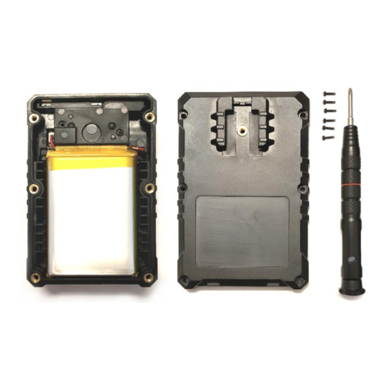
Page 26: Battery Replacement
BODYCAM 4 USER GUIDE Battery Replacement The BODYCAM 4 has a replaceable battery. A new replacement battery (P/N: BC4-BAT) can be purchased directly from PRO-VISION. Follow the procedure below to change the battery. 1. Power off camera and place lens side down on a flat surface. - Page 27 CARE AND MAINTENANCE PRO-VISION ® BODYCAM 4 USER GUIDE 5. Disconnect the original battery by gently pulling on the red/black wires in the upper left corner of the camera to disconnect the white connector from its jack. 6. Connect the new battery to the white connector in the upper left of the camera, ensure the red wire is oriented towards the top as designated.
-
Page 28: Technical Support
VISION website, www.provisionusa.com, for detailed warranty information. Radio Waves BODYCAM 4 radio transmissions are in the frequency ranges of 2402 – 2480 MHz, 2412 – 2462 MHz, 5180 – 5210 MHz, 5745 – 5825 MHz, 13.56 MHz. Changes or modifications to the equipment not expressly approved by the manufacturer could void the product warranty and the user’s authority to operate the equipment.
Need help?
Do you have a question about the BODYCAM 4 and is the answer not in the manual?
Questions and answers